
Understanding the $2,000 Problem: When Fuses Blow Without Faults
Your 100kW solar array just went offline. A technician drives 90 miles to the site, opens the combiner box, and finds a blown 15A fuse protecting a string that should only draw 12A. The fuse was sized correctly at 15A per NEC requirements (9.5A × 1.56 = 14.8A). Yet it blew anyway—no short circuit, no ground fault, just heat.
This is fuse nuisance tripping, costing the solar industry millions annually. The root cause? Temperature derating. While fuses are rated at 25°C, solar combiner boxes routinely reach 60-70°C internally. At 70°C, that 15A fuse effectively operates as a 12A fuse—right at the string’s actual current draw.
This guide provides calculation methods, derating factors, and design solutions that prevent nuisance tripping in solar combiner boxes.
Understanding Fuse Nuisance Tripping in Solar Combiner Boxes
Nuisance tripping occurs when overcurrent protection devices open the circuit without an actual electrical fault. The protection device operates at a lower threshold than its nameplate rating due to elevated operating temperatures.
How Temperature Affects Fuse Performance
Fuses operate on thermal principle: current generates heat (I²R losses). Temperature affects this in two ways:
- Reduced thermal headroom: In a 70°C environment, the fuse element starts 45°C hotter than in a 25°C lab.
- Altered resistance: Fuse element resistance increases with temperature, generating more I²R heating.
Real-World Cost Impacts
Consider a 5MW solar farm with 50 combiner boxes. If temperature-related nuisance tripping causes just 2% of boxes to require service calls annually:
- Service call: $300-500
- Fuse replacement: $75-150
- Lost production: $32-64
- Total per incident: $407-714
Studies indicate 15-25% of combiner box service calls involve nuisance tripping related to thermal issues rather than actual faults.
Temperature Derating Fundamentals
Temperature derating reduces a component’s current-carrying capacity to account for operation above the manufacturer’s specified reference conditions.
Internal Temperature vs. Ambient Temperature
The critical temperature is the internal enclosure temperature, calculated as:
T_internal = T_ambient + ΔT_solar + ΔT_component
Where:
- T_ambient = Outdoor air temperature
- ΔT_solar = Solar radiation heating (+20-35°C for metal enclosures)
- ΔT_component = Component heating (+5-15°C)
Example: 35°C + 28°C (solar) + 10°C (components) = 73°C
Fuse Temperature Derating Factors
| Ambient Temperature | Derating Factor | Effective Capacity (15A Fuse) |
|---|---|---|
| 25°C (77°F) | 1.00 | 15.0A |
| 40°C (104°F) | 0.95 | 14.3A |
| 50°C (122°F) | 0.90 | 13.5A |
| 60°C (140°F) | 0.84 | 12.6A |
| 70°C (158°F) | 0.80 | 12.0A |
Note: Always consult manufacturer’s specific derating curves for your exact fuse model.
Calculating Internal Combiner Box Temperatures
Temperature Rise Components
- 1. Ambient Temperature (T_ambient)
- Desert climates: 40-50°C
- Tropical: 32-38°C
- Temperate: 28-35°C
- 2. Solar Radiation Heating (ΔT_solar)
- Metal, dark colors, direct sun: +25-35°C
- Metal, light colors, direct sun: +18-28°C
- Shaded/ventilated: +8-15°C
- 3. Internal Component Heating (ΔT_component)
- Low current (<30A): +5-8°C
- Medium (30-60A): +8-12°C
- High (60-100A+): +12-18°C
Climate Zone Examples
| Climate Zone | T_ambient | ΔT_solar | ΔT_component | T_internal |
|---|---|---|---|---|
| Arizona Desert | 45°C | +30°C | +10°C | 85°C |
| Florida Coastal | 35°C | +25°C | +10°C | 70°C |
| California Central Valley | 38°C | +28°C | +8°C | 74°C |
| Texas High Plains | 40°C | +30°C | +10°C | 80°C |
These calculations demonstrate why combiner box overheating is critical to address.
Applying Temperature Derating to Fuse Sizing
The Complete Sizing Formula
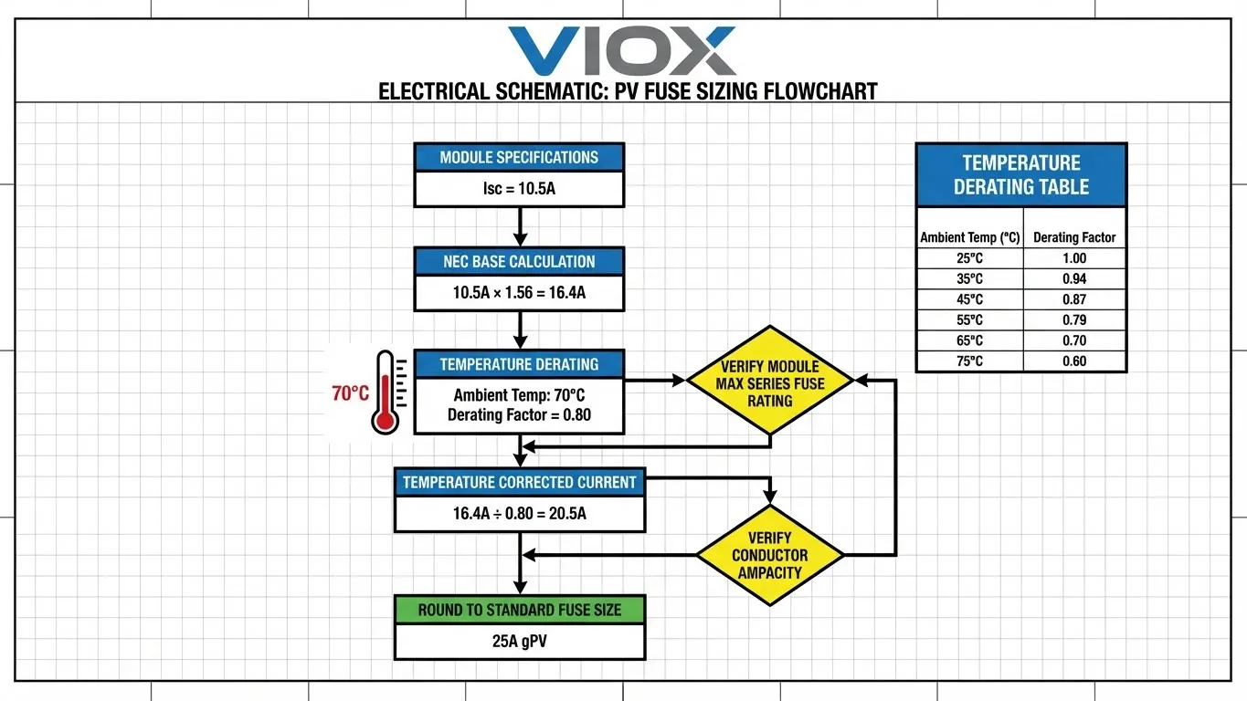
- Step 1: Calculate Maximum Circuit Current (NEC 690.8)
Per NEC 690.8(A)(1), calculate the maximum current (I_max = I_sc × 1.25). Then, apply the continuous duty factor (1.25) from NEC 690.9(B).
Formula: Base_current = I_sc × 1.56 - Step 2: Apply temperature derating
Required_fuse_rating = Base_current ÷ Derating_factor - Step 3: Round up to next standard fuse size
- Step 4: Verify against conductor ampacity
Ensure the fuse size protects the conductor after applying ambient temperature correction factors from NEC 310.15(B).
Worked Sizing Examples
Example 1: Desert Installation
- Module I_sc: 10.5A
- Internal temperature: 75°C
- Derating factor: 0.78
- Base current = 10.5A × 1.56 = 16.4A
- Temperature-adjusted = 16.4A ÷ 0.78 = 21.0A
- Standard fuse: 25A gPV fuse
Example 2: Temperate Climate
- Module I_sc: 9.2A
- Internal temperature: 55°C
- Derating factor: 0.88
- Base current = 9.2A × 1.56 = 14.4A
- Temperature-adjusted = 14.4A ÷ 0.88 = 16.4A
- Standard fuse: 20A gPV fuse
Comprehensive Sizing Table
| Module I_sc | NEC Base (1.56×) | At 60°C (0.84) | At 70°C (0.80) | Fuse (60°C) | Fuse (70°C) |
|---|---|---|---|---|---|
| 8.0A | 12.5A | 14.9A | 15.6A | 15A | 20A |
| 10.0A | 15.6A | 18.6A | 19.5A | 20A | 20A |
| 12.0A | 18.7A | 22.3A | 23.4A | 25A | 25A |
| 14.0A | 21.8A | 26.0A | 27.3A | 30A | 30A |
Critical Warning: Verify the fuse does not exceed the module’s maximum series fuse rating. For detailed requirements, see our PV fuse sizing guide.
Common Temperature Derating Mistakes
Mistake 1: Using 25°C Lab Ratings
Problem: Engineers size fuses based on NEC 1.56 multiplier alone, assuming 25°C conditions.
Consequence: A 15A fuse protecting a 9.6A I_sc string operates at only 12A capacity in a 70°C combiner box (15A × 0.80 = 12A), causing nuisance tripping.
Correction: Calculate expected internal temperature and apply derating. Required fuse: 15A ÷ 0.80 = 18.75A → 20A fuse.
Mistake 2: Ignoring Solar Radiation Heating
Problem: Designers account for ambient temperature but neglect the 20-35°C rise from solar radiation.
Correction: For direct sun installations:
- Add +20°C minimum for light-colored enclosures
- Add +25-30°C for standard metal enclosures
- Consider sunshades or shaded locations
Design Solutions to Prevent Nuisance Tripping
Solution 1: Proper Fuse Upsizing
Implementation:
- Calculate worst-case internal temperature
- Apply manufacturer derating curves
- Select next standard fuse size
- Add 10-15% safety margin
Cost: $0-50 | Effectiveness: 80-90% reduction
Solution 2: Improved Ventilation
Implementation:
- Install ventilation louvers (top and bottom)
- Minimum 3-inch mounting clearance
- Use breathable cable entry glands
Cost: $50-150 | Effectiveness: 60-75% reduction | Temp reduction: 8-15°C
Solution 3: Thermal Management
Sunshading:
- Install canopy or sunshade
- Mount on north-facing surfaces
- Use reflective coatings (white/light gray)
Cost: $100-400 | Effectiveness: 70-85% reduction | Temp reduction: 10-18°C
Solution 4: Active Cooling
Implementation:
- Solar-powered ventilation fans
- Thermostatic control (activate >50°C)
Cost: $200-800 | Effectiveness: 90-95% reduction | Temp reduction: 20-30°C
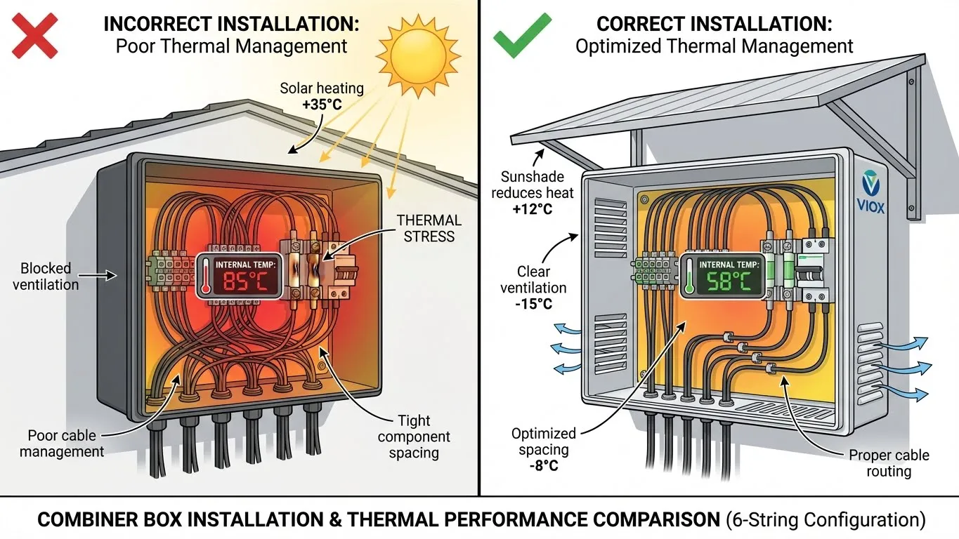
Installation Best Practices
Mounting Location
- Avoid:
- Direct mounting to dark surfaces
- South-facing walls (northern hemisphere)
- Enclosed areas with poor airflow
- Adjacent to inverters
- Prefer:
- Shaded areas behind panels
- North-facing walls with airflow
- Elevated mounting with clearance
- Natural wind flow patterns
Clearance Requirements
| Direction | Minimum Distance | Purpose |
|---|---|---|
| Front | 36 inches | NEC 110.26 working space |
| Rear | 3 inches | Air circulation |
| Sides | 6 inches | Heat dissipation |
| Top | 12 inches | Hot air exhaust |
Key Installation Points
- Mount vertically (never on back or sides)
- Maintain ventilation opening access
- Use torque screwdriver (8-12 in-lbs)
- Cable entry at bottom/sides, not top
- Avoid blocking ventilation with cable bundles
For troubleshooting guidance, see diagnosing combiner box faults.
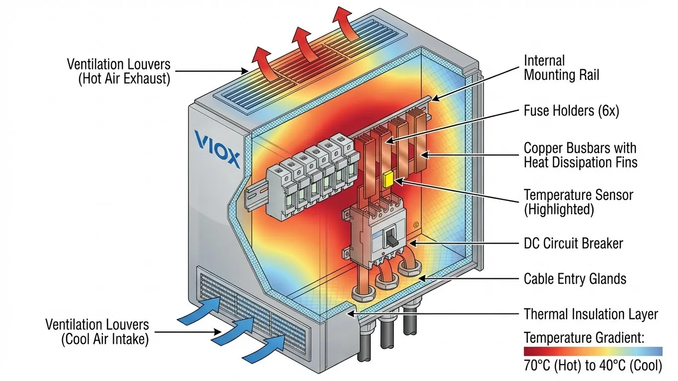
VIOX Combiner Box Thermal Management Features
VIOX Electric integrates temperature derating considerations into design from the ground up. Unlike generic enclosures that trap heat, our designs actively facilitate dissipation:
| Feature | Generic Polycarbonate Box | VIOX Thermal-Optimized Box | Impact |
|---|---|---|---|
| Material Thermal Conductivity | ~0.2 W/m·K (Insulator) | ~50 W/m·K (Steel) | VIOX dissipates heat 250x better |
| Surface Treatment | Standard Grey Plastic | Solar Reflective Coating (SRI >70) | Reduces solar gain by ~15% |
| Airflow Design | Sealed / Unvented | CFD-Optimized Louvers | Natural convection cooling |
Additional thermal features include:
- Component spacing: 30mm minimum between fuse holders to prevent thermal coupling
- Testing validation: 1,000-hour operation at 70°C ambient with thermal mapping
- Temperature monitoring: Optional NTC sensors with SCADA integration
VIOX combiner boxes typically operate 12-20°C cooler than generic alternatives under identical conditions.
FAQ Section
What temperature should I use for fuse derating?
Use the maximum expected internal enclosure temperature, not ambient air temperature. Calculate as T_internal = T_ambient + ΔT_solar + ΔT_component. For direct sunlight, add 25-35°C to ambient for solar heating, plus 8-12°C for component heating. Design for the hottest expected day. If field measurements are available, use actual data plus 5-10°C safety margin.
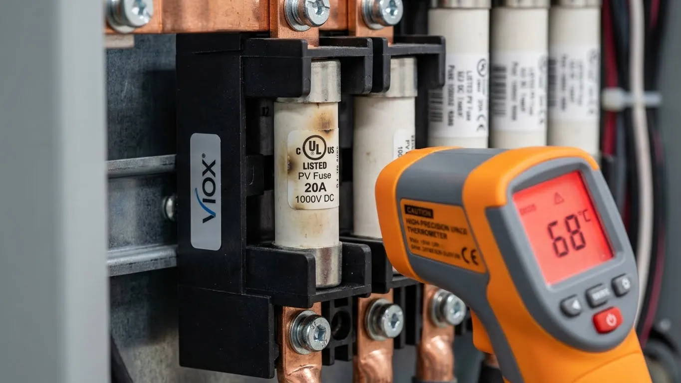
Can I use standard DC fuses instead of gPV fuses?
No—never use standard DC fuses in solar combiner boxes. gPV-rated fuses (UL 248-19 or IEC 60269-6) are mandatory per NEC 690.9 for critical reasons:
- Reverse current rating: Solar arrays can feed current backward during faults
- DC voltage rating: Required for high DC voltages (600V, 1000V, 1500V)
- Interrupt capacity: Must handle combined short-circuit current from all parallel strings
- Temperature characteristics: Designed for combiner box temperature cycling
Using non-gPV fuses violates codes, voids warranties, creates fire hazards, and may void insurance.
How do I identify nuisance tripping vs. real faults?
Nuisance tripping indicators:
- Failures during peak sunlight on hot days
- No ground fault or insulation resistance issues
- String current below fuse nameplate rating
- Multiple fuses fail correlating with temperature
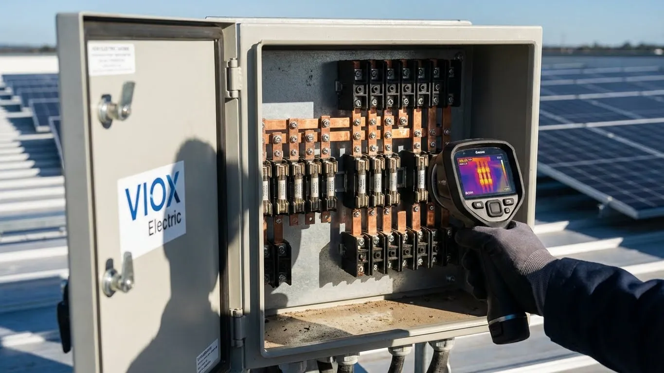
- Thermal imaging shows hot fuses without other fault evidence
Real fault indicators:
- Immediate failure upon energization
- Ground fault alarm or low insulation resistance
- Measured overcurrent condition
- Physical damage evidence
- One specific string repeatedly fails
Diagnostic procedure: Test insulation resistance, measure string I_sc, perform thermal imaging, review monitoring data, calculate temperature-derated fuse capacity.
Should I derate for both temperature AND altitude?
Yes. While temperature is the primary factor, altitude significantly impacts cooling physics. At higher altitudes (above 2,000m/6,600ft), the lower air density reduces convective cooling efficiency—meaning heat doesn’t escape the fuse or the box as easily.
- Below 6,000 feet: No altitude derating typically required for fuses.
- 6,000-10,000 feet: Add 5-10% additional oversizing to compensate for reduced air density.
- Above 10,000 feet: Consult VIOX engineering for specific high-altitude thermal modeling.
Conclusion
Fuse nuisance tripping costs the solar industry millions in unnecessary downtime and service calls. The solution is straightforward: proper sizing that accounts for temperature derating when combiner box internal temperatures reach 60-75°C.
Key principles:
- Calculate realistic internal temperatures using T_internal = T_ambient + ΔT_solar + ΔT_component
- Apply temperature derating: Required_fuse_rating = (I_sc × 1.56) ÷ Derating_factor
- Verify conductor ampacity after derating per NEC 310.15
- Implement thermal management through ventilation, sunshading, and proper spacing
- Perform regular thermal inspections to identify degradation early
For a typical 10A I_sc module in a 70°C combiner box, proper temperature-derated sizing requires a 25A fuse instead of the 15A fuse that NEC base calculations suggest—preventing nuisance tripping and saving hundreds per incident.
VIOX Electric’s combiner boxes integrate thermal management principles during design, maintaining 12-20°C lower internal temperatures than standard alternatives through ventilated enclosures, optimized component spacing, and reflective finishes.
Ready to eliminate nuisance tripping from your projects?
Don’t guess on thermal performance. Contact VIOX Electric’s engineering team today for a free thermal analysis of your site conditions, or download our Combiner Box Fuse Sizing Calculator to ensure your next installation is built to last.
