
Introduction
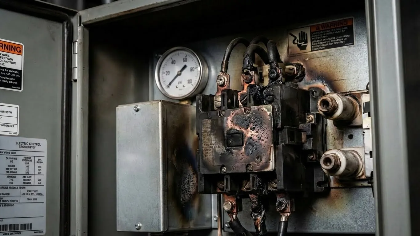
At 2:47 AM, a maintenance engineer responds to an alarm at a municipal water treatment facility. Upon opening the control panel, he discovers a disaster: the main pump contactor’s contacts have welded themselves shut, the coil insulation shows burn marks, and the acrid smell of overheated components fills the enclosure. The root cause? Pump short cycling—a phenomenon where the pressure switch rapidly toggles the pump on and off multiple times per second, creating an electrical “chatter” that destroys equipment within weeks.
This $3,200 contactor replacement could have been prevented with a $45 solution: a properly configured time delay relay. Short cycling doesn’t just damage contactors; it hammers motor windings with inrush current surges, accelerates bearing wear, and creates voltage disturbances that affect neighboring equipment. For engineers managing water supply systems, HVAC installations, or industrial fluid handling, understanding how to integrate time delay relays with pressure switches isn’t optional—it’s essential preventive maintenance.
The “Chatter” Problem: Understanding Pump Short Cycling
What Actually Happens During Short Cycling
When a pump system’s water pressure hovers near the pressure switch setpoint—say, 4.0 bar (58 psi)—the switch enters a deadly oscillation zone. The pump starts, pressure spikes to 4.1 bar, the switch opens, pressure immediately drops to 3.9 bar, the switch closes again. This cycle repeats 5-10 times per second, creating the characteristic “machine gun” clicking sound that signals imminent failure.
The problem stems from inadequate pressure switch hysteresis (differential). A properly designed switch should have a 20 psi (1.4 bar) differential between cut-in and cut-out pressures—for example, starting at 40 psi and stopping at 60 psi. However, cheap switches, miscalibrated settings, or worn mechanical components can reduce this differential to just 2-5 psi, placing the switch in perpetual hunting mode.
The Cascade of Destruction
Contactor Contact Damage: Each switch closure sends full load current through the contactor’s silver-cadmium contacts. During rapid cycling, these contacts open and close under load—the worst possible operating condition. Arcing vaporizes microscopic amounts of contact material with each cycle. After 10,000 rapid cycles (achievable in just 30 hours of chatter), contacts develop pits, carbon buildup, and high-resistance zones that generate heat. The contacts eventually weld shut or burn completely open.
Motor Winding Stress: Pump motors experience locked-rotor amperage (LRA) of 6-8 times their full load current during startup. A 10 HP motor with 28A running current draws 168-224A for the first 0.5-2 seconds. During short cycling, the motor never reaches running speed—it’s repeatedly hammered with startup surges. Motor winding insulation, rated for a specific number of thermal cycles, degrades exponentially faster. Bearings also suffer as the rotor is repeatedly accelerated and decelerated without time to establish proper lubrication films.
Relay Coil Overheating: The pump contactor’s electromagnetic coil generates heat during operation. Normal duty cycles allow for cooling between starts. Rapid cycling eliminates cooling time, causing coil temperatures to climb 40-60°C above ambient. This accelerates insulation breakdown and eventually leads to coil failure or decreased holding force, causing even more chatter.
Normal Operation vs. Short Cycling: The Critical Difference
| Parameter | Normal Operation | Short Cycling Condition |
|---|---|---|
| Cycle Frequency | 4-8 starts per hour | 300-600 starts per hour |
| Pressure Differential | 20 psi (1.4 bar) | 2-5 psi (0.14-0.35 bar) |
| Contactor Life Expectancy | 100,000-500,000 operations | 5,000-20,000 operations |
| Motor Thermal Stress | Within design limits | Exceeds thermal capacity |
| Audible Indication | Quiet relay click | Rapid “machine gun” clicking |
| Power Quality | Stable voltage | Voltage sag with each start |
| MTBF (Mean Time Between Failures) | 3-5 years | 3-6 months |
Why Pressure Switches Lack Adequate Hysteresis
Many basic pressure switches use simple snap-action mechanisms without adjustable differential settings. As springs fatigue and contact surfaces wear, the mechanical “snap” action weakens, reducing the effective pressure differential. Additionally, systems without pressure tanks or with undersized tanks experience rapid pressure changes—the pump builds pressure almost instantly in a small volume, triggering immediate shutoff.
In systems with multiple draw points (fixtures, irrigation zones, or process equipment), small leaks or dripping faucets create continuous micro-demands that hold pressure in the danger zone. The pressure never climbs high enough to fully satisfy the switch cutout, nor drops low enough to establish a stable off state.
The Time Relay Solution: Smart Logic Control
Time delay relays transform a binary pressure switch signal into intelligent, controlled pump sequencing. By introducing deliberate delays at strategic points in the control logic, these devices eliminate the conditions that cause chatter while maintaining system responsiveness.
Logic A: On-Delay Timer Protection
An on-delay timer acts as a verification gate. When the pressure switch closes (calling for pump operation), the timer’s coil energizes, but its output contacts remain open. Only after the preset time—typically 5-10 seconds—do the contacts close, allowing power to reach the contactor coil.
Key Benefits:
- False Signal Rejection: Momentary pressure dips from water hammer, valve closures, or temporary high-draw events don’t trigger unnecessary starts.
- Demand Verification: The delay ensures genuine, sustained demand exists before committing the motor to a start cycle.
- Reduced Start Frequency: Systems experiencing hunting behavior immediately stabilize, as the timer “ignores” pressure fluctuations shorter than the delay period.
Optimal Settings by Application:
- Residential water systems: 3-5 seconds
- Commercial HVAC chilled water: 5-10 seconds
- Industrial process cooling: 8-15 seconds (allows process equipment to settle)
- Irrigation systems: 5-8 seconds
The on-delay strategy works best in systems where demand events are genuinely intermittent—where starts should be infrequent and deliberate. However, it doesn’t address the shutdown phase, where chatter most commonly occurs.
Logic B: Off-Delay Timer Protection (The Primary Solution)
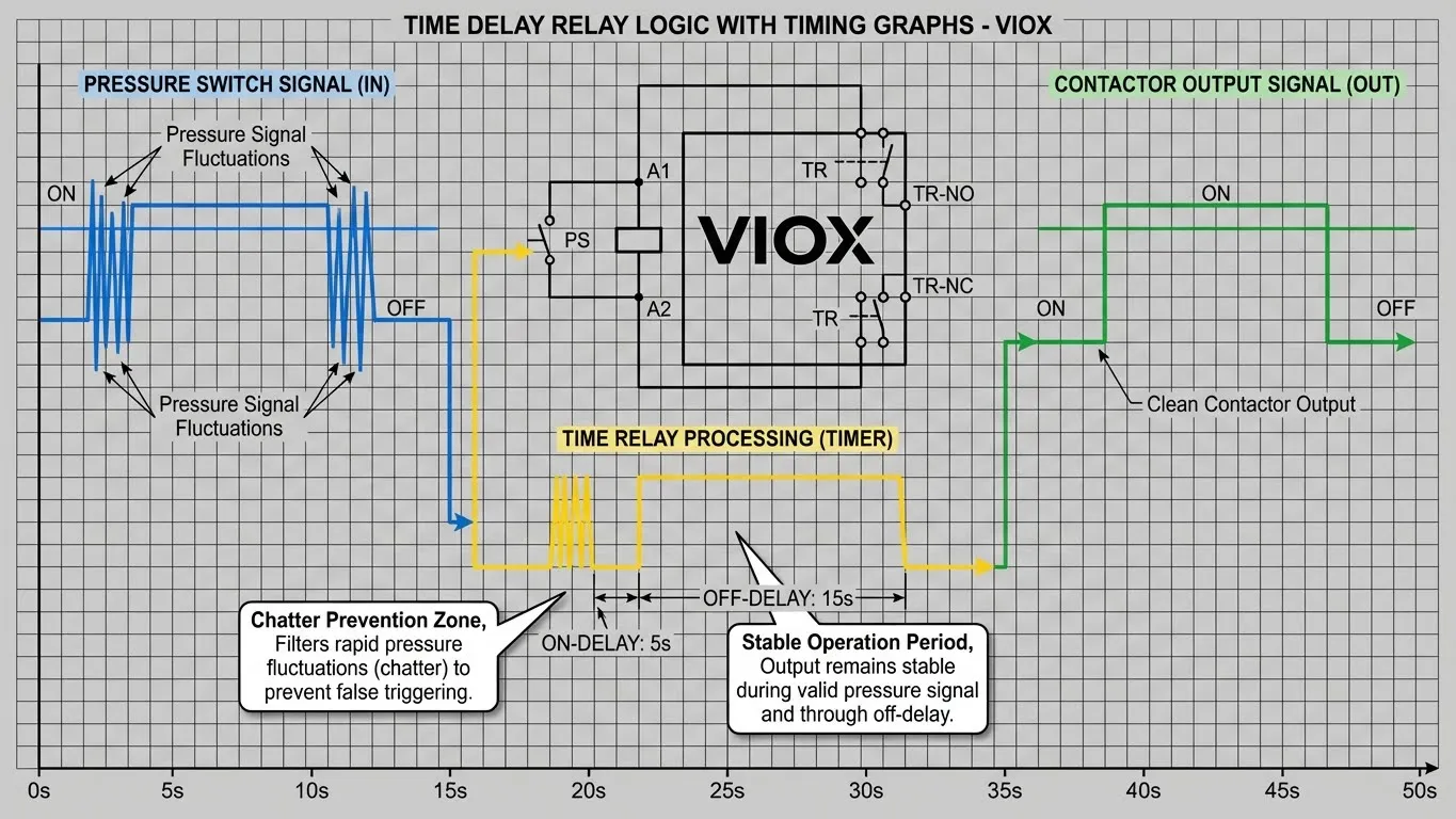
The off-delay timer is the more critical component for preventing short cycling. It operates inversely: when the pressure switch opens (indicating adequate pressure), the timer’s coil de-energizes, but its contacts remain closed for a preset duration—typically 10-20 seconds. During this “overrun” period, the pump continues operating even though the pressure switch has opened.
Why This Works:
When a pump reaches shutoff pressure and stops, system pressure doesn’t remain static. Small leaks, thermal expansion, or residual flow cause pressure to drift downward. Without off-delay protection, pressure can drop below the cutout threshold within 1-2 seconds, causing immediate restart. The off-delay timer forces the pump to run long enough to:
- Stabilize System Pressure: The extra runtime pushes pressure well above the cutout point, creating a buffer zone.
- Satisfy Transient Demands: Any minor draws occurring during the delay period are met without triggering a new start.
- Allow Pressure Tank Charging: In systems with accumulator tanks, the extended runtime ensures full tank pressurization.
Critical Application Note: Set the off-delay timer to 1.5-2× the pump’s typical run-to-shutoff time. If a pump normally runs 6 seconds before reaching cutout pressure, set the off-delay to 10-12 seconds. This prevents the timer from keeping the pump running excessively while still providing adequate protection.
The Combination Approach: Maximum Protection
For mission-critical applications or systems with severe chatter history, implement both on-delay and off-delay timers in series. This dual-timer strategy creates a “dead band” around start and stop events:
Operational Sequence:
- Pressure drops below switch cut-in → Switch closes
- On-delay timer begins 5-second verification countdown
- After 5 seconds of sustained demand → Timer energizes contactor
- Pump operates and builds pressure
- Pressure reaches cutout → Switch opens
- Off-delay timer holds contactor closed for 15 additional seconds
- After 15 seconds → Timer releases contactor, pump stops
- System enters stable off-state with pressure buffer
This approach guarantees a minimum 20-second interval between potential start attempts, making short cycling physically impossible.
Timer Logic Comparison Table
| Timer Type | Activation Trigger | Protection Point | Typical Delay Setting | Best Application | Effectiveness vs. Chatter |
|---|---|---|---|---|---|
| On-Delay | Pressure switch closes | Pump start phase | 3-10 seconds | Systems with frequent pressure transients | Moderate (60-70%) |
| Off-Delay | Pressure switch opens | Pump stop phase | 10-20 seconds | Systems with rapid pressure decay | High (85-95%) |
| Combined On + Off | Both transitions | Both start and stop | 5s on + 15s off | Critical systems, severe chatter history | Maximum (98-99%) |
| Interval Timer | External trigger | Continuous cycling applications | 30s on, 30s off | Fixed-cycle applications (fountains, irrigation) | N/A – Different use case |
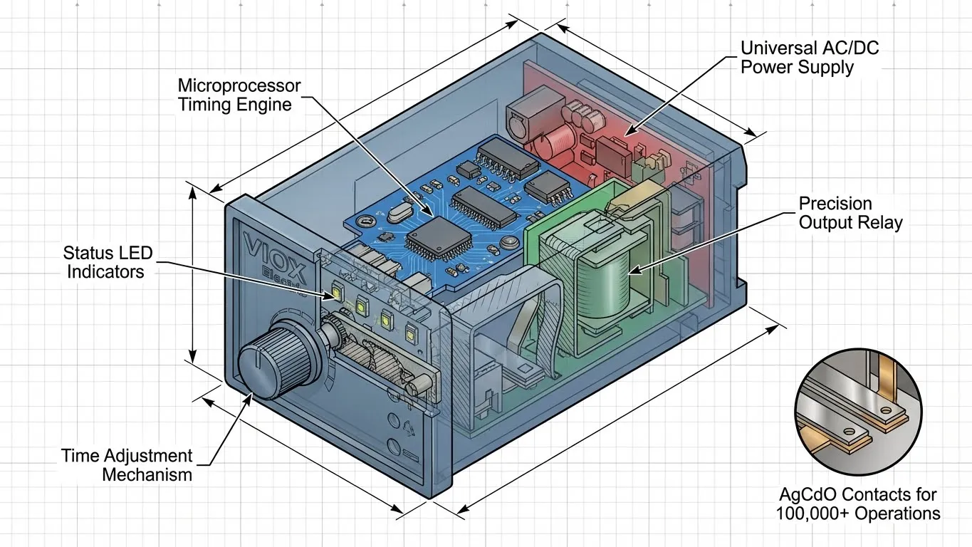
VIOX multi-function time relays feature selector switches or menu settings that allow a single device to operate in any timing mode. This flexibility means one relay model serves multiple applications, simplifying inventory and reducing field confusion.
Wiring Diagram: Practical Implementation
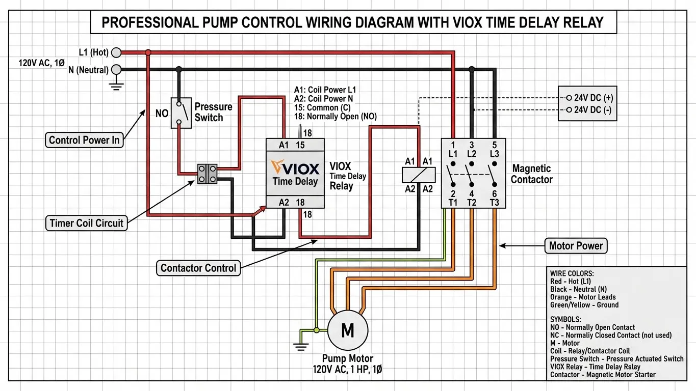
Proper time relay integration requires understanding three distinct circuits: the control power circuit, the timer control circuit, and the motor power circuit. Each operates at different voltages and serves a specific function.
Control Circuit Architecture
Circuit 1: Pressure Switch to Timer Coil (Control Power)
Line (L1, 120V or 230V AC)
    → Pressure Switch (normally open contact)
    → Time Relay Coil Terminal A1
    → Time Relay Coil Terminal A2
    → Neutral (N)
When system pressure drops below the cut-in setpoint, the pressure switch closes its contacts, completing the circuit and energizing the timer relay’s internal coil. The relay begins its timing sequence immediately. Terminal designations follow IEC standards: A1 and A2 always represent coil connections, regardless of manufacturer.
Critical Specification: The timer coil voltage must match the control circuit voltage. For industrial panels, 24V DC control is standard (powered by a transformer). Residential and light commercial applications typically use 120V AC (North America) or 230V AC (international). VIOX time relays are available in all voltage variants—always verify the relay nameplate matches your control voltage before installation.
Circuit 2: Timer Output to Contactor Coil
Line (L1, 120V or 230V AC)
    → Time Relay Output Contact Terminal 15 (COM)
    → Time Relay Output Contact Terminal 18 (NO - Normally Open)
    → Contactor Coil Terminal A1
    → Contactor Coil Terminal A2
    → Neutral (N)
After the timer completes its delay period, its normally-open (NO) output contact closes, connecting terminals 15 and 18. This completes the circuit to the contactor’s electromagnetic coil, pulling in the main power contacts. The contactor is the “muscle” of the system—its heavy-duty contacts (rated for motor inrush current) control the pump motor’s power.
Circuit 3: Contactor Power Contacts to Motor
Three-Phase Motor:
Line L1 → Contactor Main Contact 1 → Motor Terminal U1
Line L2 → Contactor Main Contact 3 → Motor Terminal V1
Line L3 → Contactor Main Contact 5 → Motor Terminal W1
Motor Terminals U2, V2, W2 → Tied together (wye) or L1/L2/L3 (delta)

Single-Phase Motor:
Line L1 → Contactor Main Contact 1 → Motor Terminal L1
Line L2/N → Contactor Main Contact 3 → Motor Terminal L2
The contactor’s main power contacts are electrically isolated from its control coil. This separation allows low-voltage control circuits (24V) to safely command high-voltage, high-current loads (480V, 50A). The contacts are rated for motor loads—standard IEC 60947 AC-3 duty—meaning they’re designed to handle 6-10× inrush current without damage.
Step-by-Step Installation Procedure
- Power Isolation: De-energize all circuits at the main disconnect. Use a multimeter to verify zero voltage at all terminals before beginning work. Lock out and tag the disconnect per OSHA 1910.147 or local safety regulations.
- Mount the Time Relay: VIOX relays feature standard 35mm DIN rail clips. Snap the relay onto the panel’s DIN rail adjacent to the contactor. Ensure at least 10mm clearance on both sides for wire routing and heat dissipation.
- Wire the Coil Circuit: Using 18 AWG (1.0 mm²) stranded wire rated for panel use (MTW, THHN), connect:
- Control hot (L1) to pressure switch common terminal
- Pressure switch NO terminal to relay terminal A1
- Relay terminal A2 to control neutral
- Wire the Output Circuit: Connect:
- Control hot (L1) to relay terminal 15 (COM)
- Relay terminal 18 (NO) to contactor coil A1
- Contactor coil A2 to control neutral
- Verify Motor Circuit Integrity: Confirm existing motor wiring to contactor main contacts follows NEC/IEC requirements. Motor leads should be sized per NEC 430.22 (125% of motor FLA). Do not modify motor power wiring during timer installation.
- Configure Timer Settings:
- Set function selector to “Off-Delay” mode (consult relay documentation for switch positions)
- Adjust time delay potentiometer or digital setting to 15 seconds (starting point)
- For combination protection, install second relay in series using on-delay mode with 5-second setting
- Functional Testing:
- Restore power to control circuit only (leave motor disconnect open)
- Manually close pressure switch or jumper switch terminals
- Verify timer coil energizes (LED indicator illuminates on VIOX relays)
- Wait 5 seconds (on-delay) and confirm contactor coil clicks (audible pull-in)
- Open pressure switch / remove jumper
- Confirm contactor remains closed for 15 seconds (off-delay) before releasing
- If timing is incorrect, adjust delay settings and repeat test
- Commission Under Load:
- Close motor disconnect
- Allow system to operate through 3-5 complete cycles
- Monitor pressure gauge for stable operation without hunting
- Observe that pump stops are deliberate, not abrupt
- Listen for absence of contactor chattering
Safety and Code Compliance
- Wire Sizing: Control circuit wires must meet NEC 725 requirements. For 24V DC control drawing <1A, 18 AWG is adequate. For 120V AC control, use minimum 16 AWG.
- Overcurrent Protection: Install a 2A fuse or circuit breaker in the control hot line to protect against short circuits in the timer or wiring.
- Enclosure Rating: Time relays must be mounted in enclosures rated for the environment—NEMA 1 (indoor dry), NEMA 4X (outdoor/corrosive), or Ex-rated (hazardous locations).
- Ground Continuity: Verify ground bonding between panel chassis, contactor frame, and motor PE terminal per NEC 250.
For detailed relay terminal identification and advanced wiring scenarios, consult VIOX’s comprehensive time delay relay wiring guide.
Product Selection: Why VIOX Time Relays Excel
Multi-Function Flexibility
Standard single-function timers lock you into one operating mode—if field conditions change or you need different logic for a new application, you’re replacing hardware. VIOX multi-function time relays eliminate this limitation with mode selector switches or digital menu systems offering 8-16 timing functions in one device:
- On-delay (Power-on delay)
- Off-delay (Power-off delay)
- Single-shot interval
- Repeat cycle (Flasher)
- Star-delta motor control timing
- Sequential timing with memory
For pump applications, the critical functions are on-delay and off-delay. A single VIOX relay handles both by changing a selector switch position—no rewiring required. This means you can start with off-delay (the most common need), then add on-delay protection later if system behavior warrants it, using the same relay.
Universal Voltage Compatibility
Pump control panels exist in every voltage configuration imaginable. A residential well pump runs on 120V AC control. Industrial chilled water systems use 24V DC logic. European installations default to 230V AC. Buying voltage-specific relays for each application inflates inventory costs and creates field installation errors.
VIOX offers both fixed-voltage and universal-input models:
- Fixed: 12V DC, 24V DC, 24-48V AC/DC, 110-120V AC, 220-240V AC
- Universal: 12-240V AC/DC (auto-ranging)
Universal-input relays automatically detect and adapt to the applied voltage, making them ideal for OEM panel builders or service organizations supporting diverse equipment.
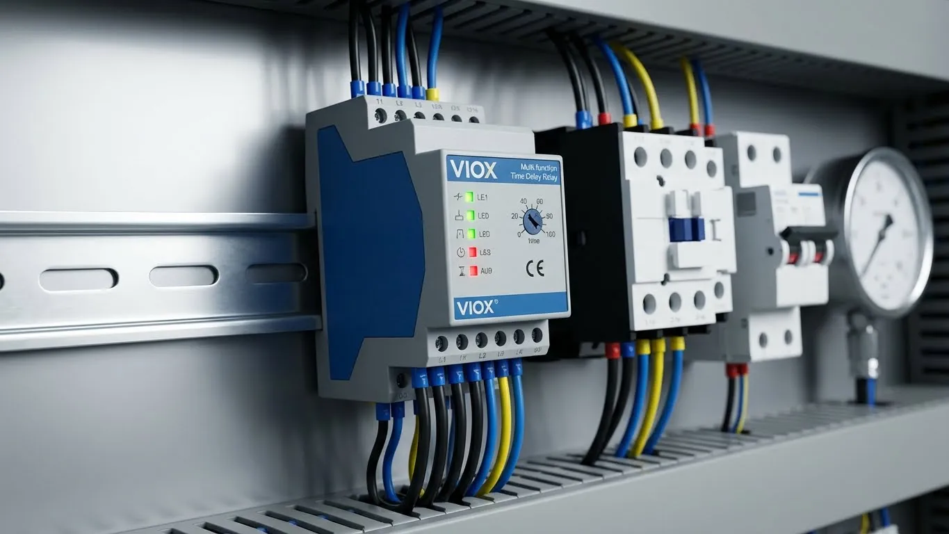
DIN Rail Mounting for Professional Integration
Unlike panel-mount timers requiring knockout punching and rigid mounting brackets, VIOX relays snap onto standard 35mm DIN rail in seconds. This matters in retrofit situations where adding a timer to an existing crowded panel is challenging. DIN rail mounting also allows tool-free relay replacement—if a relay fails (rare, but possible), a maintenance tech snaps in a replacement in under 60 seconds.
Each relay occupies 1-2 DIN rail modules (18-36mm width), consuming minimal panel space. For comparison, a traditional 11-pin relay in an octal base consumes a 35×35mm footprint plus requires a separate mounting base (additional $12 cost).
Specification Comparison: VIOX vs. Generic Alternatives
| Feature | VIOX Multi-Function Timer | Generic Single-Function Timer | Electromechanical Delay Relay |
|---|---|---|---|
| Time Range Adjustment | 0.05s – 999 hours (digital) | Fixed or limited (0.1-10s typical) | 1-60 seconds (mechanical) |
| Timing Accuracy | ±0.5% + 20ms | ±5-10% | ±10-15% (drift over time) |
| Operating Modes | 8-16 functions selectable | Single mode only | On-delay or off-delay (fixed) |
| Repeat Accuracy | <50ms deviation cycle-to-cycle | ±2-5% | Degrades 5-10% annually |
| LED Status Indication | Coil power + timing status + output state | None or single LED | None |
| Contact Rating | 5A @ 250V AC resistive / 2A @ 30V DC | 5-10A (varies) | 10A but degrades rapidly under motor load |
| Mounting | DIN rail (35mm, snap-on) | Panel mount (requires drilling) | 11-pin octal base (requires socket) |
| Expected Service Life | 100,000 hours (solid-state switching) | 50,000 operations (mechanical relay) | 10,000-30,000 operations |
| Temperature Range | -25°C to +55°C | 0°C to +50°C | 10°C to +40°C |
| Price | $42-68 USD | $18-35 USD | $25-40 USD + $12 socket |
| Installation Time | <5 minutes | 15-30 minutes | 10-20 minutes |
Cost-Benefit Analysis:
A burned contactor replacement costs $180-450 for the contactor alone, plus 2-4 hours of labor ($200-600), plus system downtime (varies: $500-5,000 depending on criticality). Total incident cost: $880-6,050.
A VIOX time relay installation costs $42-68 for the relay plus 30-60 minutes of labor ($75-150). Total prevention cost: $117-218.
ROI Calculation: Preventing a single contactor failure pays for 4-8 time relays. In facilities with multiple pumps (water treatment plants typically have 3-6 pumps), the business case is overwhelming.
Application-Specific Time Settings Guide
| Application | On-Delay Setting | Off-Delay Setting | Reasoning |
|---|---|---|---|
| Residential Well Pump | 3-5 seconds | 10-15 seconds | Low flow rate, small pressure tank, frequent fixture use |
| Commercial Building Water Booster | 5-8 seconds | 15-20 seconds | Multiple fixtures, larger tank, higher flow demand |
| HVAC Chilled Water Circulation | 8-12 seconds | 20-30 seconds | High inertia system, thermal response delay |
| Industrial Process Cooling | 10-15 seconds | 25-40 seconds | Process equipment thermal mass requires extended operation |
| Irrigation Zone Pump | 5-8 seconds | 12-18 seconds | Moderate flow, solenoid valve delay compensation |
| Fire Suppression Jockey Pump | 2-3 seconds | 5-8 seconds | Fast response required, but still needs chatter protection |
Configuration Note: Always start with manufacturer-recommended settings, then fine-tune based on observed system behavior. If pressure hunting persists, increase off-delay time by 5-second increments. If pump runs excessively long, reduce off-delay time. Document final settings on the panel schematic for future reference.
Explore the complete range of VIOX timing solutions at https://viox.com/timer-relay.
Frequently Asked Questions
Q1: What time delay setting should I use for my pump?
Start with a 15-second off-delay as the baseline for most applications. This provides adequate chatter protection without excessive overrun. Observe system behavior over 24 hours: if the pump still exhibits rapid cycling, increase to 20-25 seconds. If the pump seems to run too long after pressure is satisfied, reduce to 10-12 seconds. On-delay settings are less critical—5 seconds works for 90% of installations. In systems where pressure transients are rare, you can omit on-delay entirely and use only off-delay protection.
Q2: Can I retrofit a time relay into an existing pump control system?
Yes, retrofitting is straightforward in most cases. The time relay inserts between the existing pressure switch and the contactor coil, requiring no modification to motor power wiring. You’ll need access to the control circuit, typically 120V AC or 24V DC. Installation takes 30-60 minutes for someone with basic electrical skills. The only scenario requiring panel redesign is when no space exists for DIN rail mounting—in this case, consider a panel upgrade or external timer enclosure.
Q3: Will a time relay work with both submersible and jet pumps?
Absolutely. The time relay operates on the control signal—it’s agnostic to the motor type, horsepower, or pump configuration. Whether you’re controlling a 0.5 HP residential submersible, a 10 HP commercial booster pump, or a 100 HP industrial process pump, the same relay works. The relay controls the contactor’s coil (a few watts), not the motor itself (kilowatts). Ensure your contactor is properly sized for the motor load—the timer simply adds intelligence to the contactor’s operation.
Q4: How do I know if my pump is short cycling?
Listen for rapid clicking from the contactor—a healthy system clicks once per start, then silence until the next demand event. Short cycling produces a “machine gun” sound of 3-10 clicks per second. Check your pressure gauge: in a healthy system, pressure cycles between two distinct setpoints with 15-20 psi spread. A short cycling system shows pressure fluctuating rapidly in a narrow 2-5 psi band. Count starts: a residential pump should start 4-8 times per hour during normal use. If you’re seeing 15+ starts per hour, short cycling is occurring. Examine contactor contacts: if they’re pitted, discolored, or have carbon buildup despite being <1 year old, short cycling is the culprit.
Q5: What’s the difference between on-delay and off-delay timers?
On-delay: Delays the action AFTER the input signal arrives. Pressure switch closes → timer counts 5 seconds → relay closes output → contactor pulls in. Think “wait before starting.” Best for preventing false starts from momentary pressure dips.
Off-delay: Maintains the action AFTER the input signal disappears. Pressure switch opens → timer holds output closed for 15 seconds → relay finally opens output → contactor drops out. Think “keep running after signal ends.” Best for preventing rapid restart after pressure is satisfied. For pump chatter prevention, off-delay is the primary solution—it addresses the shutdown phase where most oscillation occurs.
Q6: Do I need an electrician to install a time relay?
Installation requirements depend on local electrical codes. In commercial and industrial settings, only licensed electricians or qualified maintenance personnel should perform control circuit modifications. For residential applications in many jurisdictions, homeowners can legally work on their own systems, but we strongly recommend professional installation for several reasons: proper control voltage identification, correct terminal connections, and code-compliant overcurrent protection. An improperly installed timer can create safety hazards or fail to solve the chatter problem. Budget $150-300 for professional installation—it’s inexpensive insurance against equipment damage.
For comprehensive timer selection guidance, see How to Choose the Right Timer Relay.
Conclusion: The Verdict on Time Relay Integration
✅ Strongly Recommended for any pump system experiencing short cycling or operating in environments with frequent pressure fluctuations.
Time delay relays represent mature, proven technology that solves a specific, costly problem with elegant simplicity. Rather than redesigning pressure switches, upgrading to variable-frequency drives, or accepting accelerated equipment wear, adding a $50 timer delivers 90-95% chatter elimination in a 30-minute installation. The return on investment manifests immediately: eliminated contactor replacements, extended motor life, reduced maintenance calls, and improved system reliability.
For facilities engineers managing multiple pump systems—water treatment plants, HVAC mechanical rooms, industrial process cooling—standardizing on VIOX multi-function time relays creates operational benefits beyond the technical solution. Inventory consolidation (one relay model serves 10+ applications), reduced training requirements (maintenance staff learns one platform), and streamlined troubleshooting all contribute to lower total cost of ownership.
The technology’s ROI is irrefutable: preventing a single contactor failure ($880-6,050 incident cost) pays for the relay installation 4-28 times over. In mission-critical applications where pump failure creates safety risks or production losses measured in thousands per hour, the business case becomes overwhelming.
Key Takeaways:
- Off-delay timers solve 85-95% of short cycling problems by preventing rapid restart after pressure cutout
- Combined on-delay + off-delay approaches provide 98-99% protection in severe cases
- VIOX multi-function relays offer superior flexibility, accuracy, and service life compared to generic alternatives
- Installation requires basic electrical skills but professional installation is recommended for code compliance
- Time settings are application-dependent: start with 5s on-delay + 15s off-delay and adjust based on observed behavior
Take Action
Ready to eliminate pump short cycling from your facility? Browse VIOX’s complete range of time delay relays at https://viox.com/timer-relay, where you’ll find detailed specifications, application notes, and selection tools. For technical assistance with product selection or custom panel integration, contact a VIOX Electric application engineer through the website’s live chat or submit a technical inquiry form.
For maintenance teams implementing preventive measures, also review VIOX’s industrial contactor maintenance checklist to identify early warning signs of chatter-related damage before complete failure occurs. Combining time relay installation with systematic contactor troubleshooting creates a comprehensive equipment protection strategy that maximizes uptime and minimizes emergency repair costs.
The choice is clear: invest 30 minutes and $50 in a time relay now, or pay $3,000+ for emergency contactor replacement later. Engineering isn’t about choosing between good and bad solutions—it’s about choosing the solution that delivers the best return on investment while maintaining safety and reliability. Time delay relay integration checks every box.
