Na tej stronie
Przepust transformatorowy to izolowany element przewodzący prąd, który umożliwia przejście wyprowadzenia uzwojenia transformatora przez uziemiony metalowy zbiornik bez nawiązywania z nim kontaktu elektrycznego. Zapewnia on separację dielektryczną oraz wsparcie mechaniczne; w zależności od konstrukcji, zainstalowany zespół przepustu pomaga również zachować szczelność bariery cieczy lub gazu transformatora.
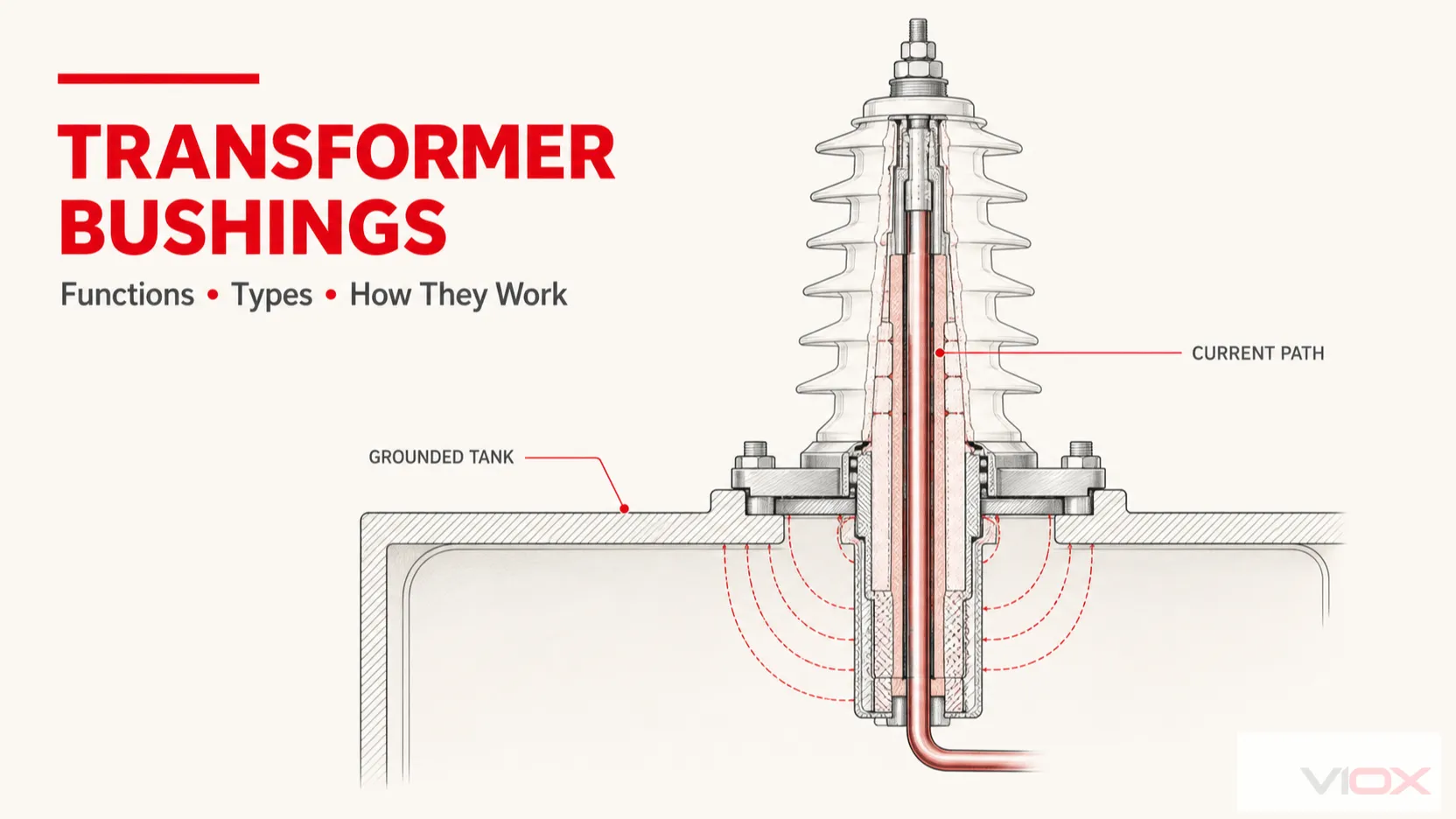
To umiejscowienie w systemie jest kluczem do zrozumienia tego komponentu. Przepust to nie tylko widoczna obudowa porcelanowa lub polimerowa na szczycie transformatora. Jest to kompletne przejście pomiędzy przewodem wewnętrznym pod napięciem, uziemionym zbiornikiem lub kołnierzem a zewnętrznym połączeniem systemu elektroenergetycznego.
Gdzie znajduje się przepust transformatorowy?
Wewnątrz transformatora wyprowadzenie uzwojenia musi zostać połączone z zewnętrznym przewodem napowietrznym, kablem, szynoprzewodem lub złączem rozłączalnym. Ponieważ zbiornik transformatora jest zazwyczaj uziemiony, wyprowadzenie nie może przechodzić bezpośrednio przez metalową ściankę. Przepust tworzy kontrolowaną ścieżkę izolacyjną przez tę barierę.
Typowy układ zawiera:
- centralny przewód prądowy lub przejście dla przewodu wyciąganego lub drążka wyciąganego;
- izolację wewnętrzną pomiędzy przewodem a uziemionym kołnierzem montażowym;
- zewnętrzna obudowa izolacyjna z żebrami, gdzie wymagana jest izolacja powietrzna i droga upływu;
- kołnierz lub konstrukcja montażowa przymocowana do kadzi transformatora;
- zaciski lub osprzęt połączeniowy po stronie transformatora i instalacji elektrycznej; oraz
- uszczelnienia odpowiednie dla medium izolacyjnego transformatora i konstrukcji przepustu.
Prowadzi to do prostego modelu systemu:
uzwojenie transformatora → wyprowadzenie wewnętrzne → przewodnik przepustu → zacisk zewnętrzny → przewodnik systemu elektroenergetycznego
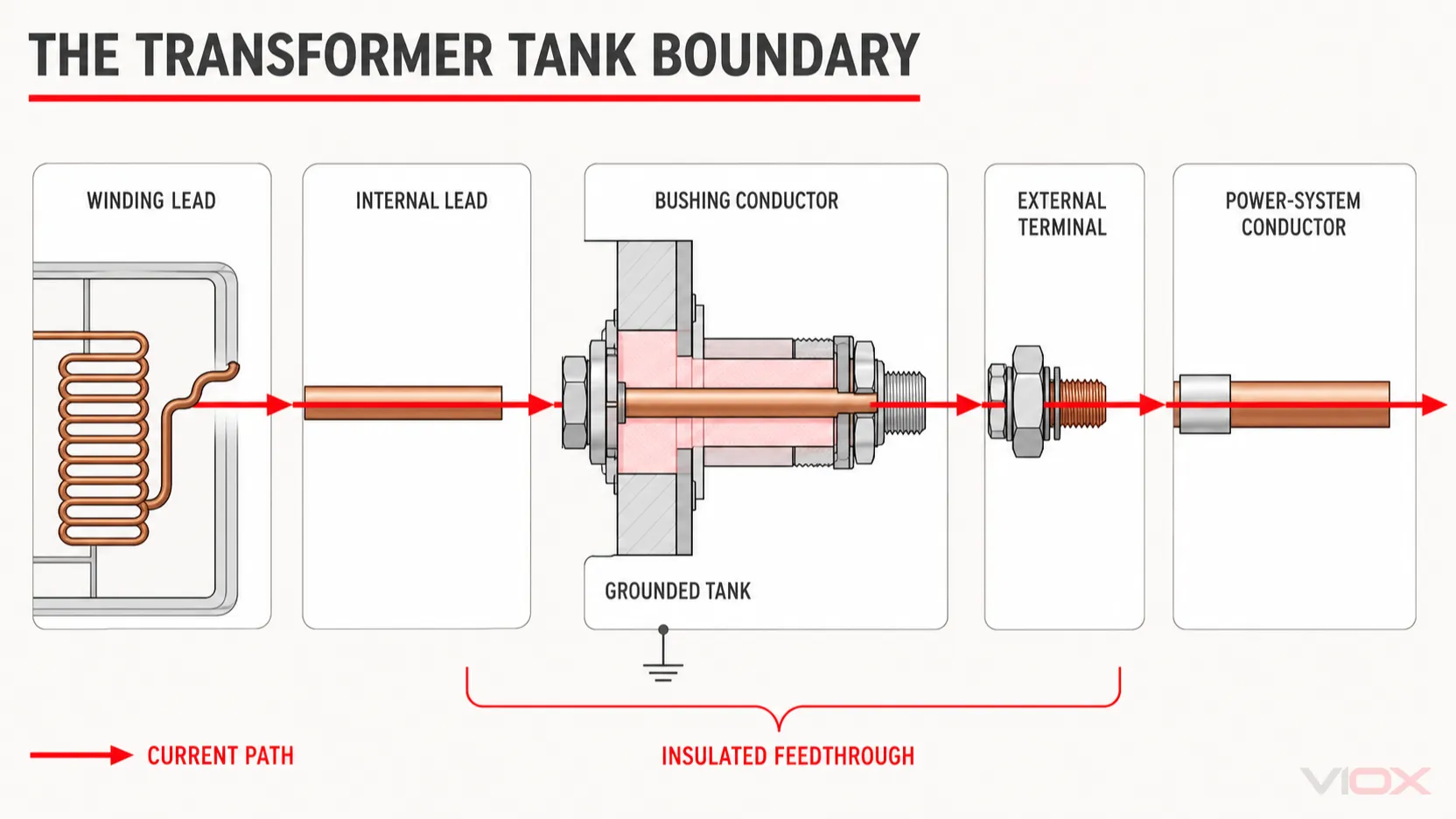
Uziemiona kadź otacza część tej ścieżki, dlatego przepust musi radzić sobie zarówno z naprężeniami elektrycznymi, jak i fizycznym przejściem przez kadź.
Jaką funkcję pełni przepust transformatorowy?
Komponent pełni kilka powiązanych funkcji w obrębie tej samej granicy.
| Funkcja | Zadania, które musi spełniać przepust izolacyjny | Co może pójść nie tak w przypadku utraty funkcji |
|---|---|---|
| Przewodzenie prądu | Zapewnienie ciągłej ścieżki przewodzącej między wyprowadzeniem uzwojenia a obwodem zewnętrznym | Miejscowe nagrzewanie, uszkodzenie połączenia lub utrata ciągłości |
| Zapewnienie izolacji dielektrycznej | Utrzymanie przewodu pod napięciem w stanie odizolowania elektrycznego od uziemionego zbiornika i kołnierza | Przeskok powierzchniowy lub przebicie izolacji wewnętrznej |
| Kontrola naprężeń elektrycznych | Kształtowanie pola elektrycznego poprzez geometrię oraz, w konstrukcjach stopniowanych, wewnętrzne warstwy przewodzące | Nadmierna koncentracja naprężeń i degradacja izolacji |
| Przenoszenie obciążeń mechanicznych | Utrzymywanie zacisku i przewodu w odpowiedniej pozycji przy normalnych obciążeniach eksploatacyjnych | Pęknięcia, przemieszczenia, uszkodzenia uszczelnień lub naprężenia połączeń |
| Utrzymanie szczelności urządzenia | Pomagają zapobiegać wyciekom cieczy lub gazu izolacyjnego oraz przedostawaniu się wilgoci lub zanieczyszczeń, jeśli konstrukcja stanowi część tej bariery | Wyciek, zanieczyszczenie lub obniżona wytrzymałość dielektryczna |
Funkcje te są od siebie zależne. Na przykład uszkodzona uszczelka to nie tylko problem mechaniczny: wnikanie wilgoci lub utrata medium izolacyjnego może również wpłynąć na parametry dielektryczne.
Jak działa przepust transformatorowy?
Podstawową zasadą jest kontrolowana izolacja między dwoma potencjałami elektrycznymi. Przewodnik środkowy znajduje się pod napięciem, podczas gdy kołnierz montażowy i zbiornik transformatora znajdują się na potencjale ziemi. Materiał izolacyjny między nimi musi wytrzymać napięcie występujące na tej granicy bez przebicia, przeskoku iskrowego lub niedopuszczalnego prądu upływu.
Od strony powietrznej obudowa zapewnia odstęp izolacyjny w powietrzu oraz dłuższą drogę upływu wzdłuż powierzchni. Klosze zwiększają tę drogę powierzchniową i pomagają radzić sobie z wpływem warunków środowiskowych. Wymagana geometria zależy od napięcia, warunków zanieczyszczenia, koordynacji izolacji oraz obowiązującej specyfikacji projektowej.
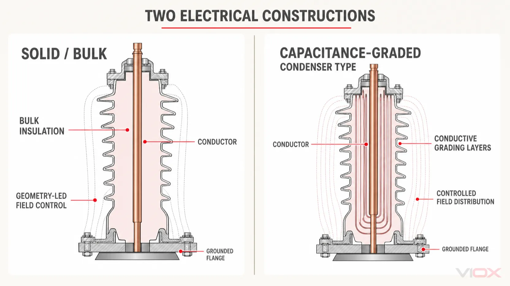
Wewnątrz przepustu typu litego lub masowego, izolacja opiera się głównie na masie materiału dielektrycznego i geometrii komponentu. Konstrukcje te są powszechnie stosowane w połączeniach transformatorowych niskiego napięcia, chociaż prawidłowe zastosowanie zależy od zweryfikowanych parametrów znamionowych przepustu, a nie od ogólnego oznaczenia napięcia.
W przepust z izolacją pojemnościową, przewodzące warstwy wyrównawcze są umieszczone wewnątrz głównej izolacji wokół przewodu centralnego. Warstwy te tworzą kontrolowany szereg pojemności, które bardziej równomiernie rozkładają naprężenia elektryczne między przewodem a uziemionym kołnierzem. Ta konstrukcja z rdzeniem kondensatorowym jest szeroko stosowana tam, gdzie naprężenia napięciowe wymagają bardziej precyzyjnej kontroli pola.
Warstwy wyrównawcze nie są dodatkowymi zaciskami prądowymi. Ich celem jest kontrola pola elektrycznego wewnątrz układu izolacyjnego.
Typy przepustów transformatorowych: Wybierz właściwą oś klasyfikacji
Wiele artykułów przedstawia jedną długą listę “typów” przepustów, ale etykiety te często opisują różne zagadnienia inżynieryjne. Bardziej przejrzystym podejściem jest rozdzielenie czterech osi klasyfikacji.
| Oś klasyfikacji | Główne kategorie | Co mówi klasyfikacja |
|---|---|---|
| Konstrukcja elektryczna | Lita/masywna; z gradacją pojemnościową/kondensatorowa | W jaki sposób izolacja główna radzi sobie z naprężeniami elektrycznymi |
| Technologia izolacji głównej | Papier impregnowany olejem (OIP); papier impregnowany żywicą (RIP); tworzywa sztuczne impregnowane żywicą (RIS) | Układ materiałowy zastosowany w rdzeniu kondensatorowym lub konstrukcji przepustu |
| Interfejs serwisowy | Ciecz-powietrze; ciecz-ciecz; ciecz-gaz; powietrze-powietrze, w zależności od urządzenia | Środowiska izolacyjne, które łączy przepust |
| Zacisk lub interfejs urządzenia | Typy z przewodem wciąganym (draw-lead), prętem wciąganym (draw-rod), przyłączem dolnym, skrzynką kablową, z dostępem do części pod napięciem (live-front), z izolowaną osłoną (dead-front) oraz inne układy specyficzne dla danego zastosowania | Sposób połączenia przewodu z systemem zewnętrznym |
Kategorii tych nie należy traktować jako wzajemnie wykluczających się alternatyw. Jeden przepust może być konstrukcją z izolacją pojemnościową, typu RIP, typu ciecz-powietrze z określonym układem zacisków. Każda etykieta opisuje inną cechę.
Przepusty lite lub typu masowego
Konstrukcja lita/masowa wykorzystuje stosunkowo prosty korpus izolacyjny bez rdzenia kondensatorowego. Porcelana, żywica epoksydowa lub inny materiał dielektryczny stanowią główną izolację, a niektóre konstrukcje wykorzystują również olej transformatorowy w przestrzeni wokół przewodu. Dokładna konstrukcja może się różnić, dlatego określenia “lity” nie należy interpretować jako oznaczającego, że każda część jest pozbawiona cieczy.
Ta kategoria jest często stosowana w uzwojeniach niskiego napięcia oraz w urządzeniach rozdzielczych. Powinna być nadal określana na podstawie rzeczywistych wartości znamionowych napięcia, prądu, izolacji, wymiarów oraz warunków środowiskowych.
Przepusty kondensatorowe lub z izolacją stopniowaną pojemnościowo
Przepust kondensatorowy zawiera specjalnie zaprojektowany rdzeń z warstwami wyrównawczymi (ekranami) osadzonymi w obliczonych odstępach. Powstała w ten sposób sieć pojemnościowa kontroluje naprężenia elektryczne w kierunku promieniowym i osiowym skuteczniej niż sama geometria.
Niektóre przepusty stopniowane posiadają odczep pomiarowy lub napięciowy połączony z zewnętrzną warstwą wyrównawczą. Funkcja ta umożliwia wykonywanie pomiarów stanu technicznego w kompatybilnych konstrukcjach, jednak jej użycie, sposób uziemienia oraz procedura testowa należą do wykwalifikowanego personelu postępującego zgodnie z instrukcjami producenta przepustu. Nie jest to ogólne złącze elektryczne.
Przepusty OIP, RIP i RIS
Poniższe skróty określają główne technologie izolacji, a nie trzy uniwersalne klasy zastosowań:
- OIP — papier impregnowany olejem: rdzeń kondensatorowy na bazie papieru impregnowany olejem izolacyjnym.
- RIP — papier impregnowany żywicą: rdzeń kondensatorowy na bazie papieru, impregnowany i utwardzony żywicą w celu utworzenia litego korpusu.
- RIS — materiały syntetyczne impregnowane żywicą: technologia rdzenia kondensatorowego wykorzystująca materiał syntetyczny impregnowany żywicą.
Sama technologia nie przesądza o przydatności. Kompletna specyfikacja przepustu musi uwzględniać parametry elektryczne, interfejs, geometrię montażu, izolację zewnętrzną, medium transformatorowe, obciążenia mechaniczne oraz zweryfikowane dane producenta.
Czy przepusty typu Live-Front i Dead-Front to różne typy?
Określają one dostępność i ekranowanie interfejsu połączeniowego, szczególnie w urządzeniach rozdzielczych szafkowych. Zakończenie typu live-front posiada odsłonięte części pod napięciem, gdy przedział jest dostępny, podczas gdy system typu dead-front wykorzystuje ekranowane złącza rozłączne, które po prawidłowym montażu zapewniają uziemioną powierzchnię zewnętrzną.
To rozróżnienie jest istotne, ale nie stanowi tej samej klasyfikacji co izolacja lita kontra izolacja z gradacją pojemnościową lub OIP kontra RIP. Mieszanie tych terminów w jednej liście zaciera decyzje projektowe, które w rzeczywistości reprezentują.
Które parametry znamionowe przepustów transformatorowych są istotne?
Nazwa lub oznaczenie materiału nie wystarczą do identyfikacji przepustu przeznaczonego na wymianę lub nowego elementu. Poniższe pola wyjaśniają główne granice inżynieryjne, jednak nie zastępują one procesu doboru zatwierdzonego przez producenta.
| Pole wartości znamionowej lub specyfikacji | Dlaczego to ma znaczenie |
|---|---|
| Najwyższe napięcie urządzenia (Um) lub odpowiednia klasa napięciowa | Określa granicę napięcia układu izolacyjnego stosowaną zgodnie z odpowiednią normą i specyfikacją urządzenia |
| Prąd znamionowy | Odnosi się do obciążalności prądowej ciągłej oraz wzrostu temperatury w określonych warunkach |
| Poziom izolacji | Definiuje wymagane poziomy wytrzymałości na napięcie o częstotliwości sieciowej oraz napięcie udarowe dla koordynacji izolacji |
| Droga upływu i profil izolacji zewnętrznej | Dotyczy parametrów izolacji powierzchniowej oraz narażenia na czynniki środowiskowe lub zanieczyszczenia |
| Częstotliwość oraz obciążenie AC/DC | Zapobiega automatycznemu stosowaniu normy lub konstrukcji przepustu AC w systemach DC |
| Interfejs serwisowy | Potwierdza kompatybilność z powietrzem, cieczą transformatorową, urządzeniami izolowanymi gazem lub innym medium |
| Układ przewodów i zacisków | Określa połączenie elektryczne, ścieżkę prądową oraz kompatybilność instalacyjną |
| Kołnierz i interfejs wymiarowy | Określa, czy przepust pasuje fizycznie i zachowuje wymaganą granicę urządzenia |
| Wymagania mechaniczne i środowiskowe | Obejmują obciążenia zacisków, wymogi sejsmiczne, wysokość n.p.m., warunki temperaturowe oraz środowisko instalacji, jeśli ma to zastosowanie |
| Dane referencyjne dotyczące pojemności oraz strat/współczynnika mocy | Dostarczyć informacje o warunkach bazowych dla kompatybilnych przepustów izolatorowych oraz zatwierdzonych programów diagnostycznych |
Terminologia napięciowa różni się w zależności od normy i rynku. Przewodnik VIOX dotyczący klasyfikacji niskiego, średniego i wysokiego napięcia wyjaśnia, dlaczego nieformalne oznaczenia napięcia nie powinny zastępować wartości podanych w dokumentacji przepustu i transformatora.
Przepust transformatorowy a szyna zbiorcza lub izolator wsporczy
Wszystkie trzy komponenty wykorzystują materiały dielektryczne, ale zajmują różne pozycje i rozwiązują różne problemy w instalacji elektrycznej.
| Komponent | Podstawowa pozycja w systemie | Przewodzi prąd? | Przechodzi przez uziemioną obudowę? | Główne zadanie |
|---|---|---|---|---|
| Przepust transformatorowy | Granica kadzi transformatora | Przewodnik centralny lub przewód wyprowadzenia przewodzi prąd | TAK | Przenoszą połączenie pod napięciem przez uziemioną kadź, zachowując izolację i integralność mechaniczną |
| Izolator szynowy | Wewnątrz rozdzielnic, paneli, szynoprzewodów lub zespołów rozdzielczych | Zazwyczaj nie | Zazwyczaj nie | Podpierają i oddzielają szynę zbiorczą od uziemionych konstrukcji lub innych przewodów |
| Izolator wsporczy | Pomiędzy przewodem/komponentem a jego powierzchnią montażową | Zazwyczaj nie | NIE | Utrzymują odstęp fizyczny i izolację dielektryczną, jednocześnie podpierając zamontowany element |
W kwestii granicy sąsiedniego komponentu, patrz Co to jest izolator szyn zbiorczych? oraz porównanie VIOX izolatory wsporcze a izolatory szynowe.
Kluczowa różnica polega na tym, że przepust transformatorowy jest przepustem elektrycznym. Izolator szynowy lub wsporczy zazwyczaj podtrzymuje oddzielny element przewodzący prąd, zamiast tworzyć połączenie przechodzące przez zbiornik.
Co wskazuje na to, że przepust transformatorowy może wymagać oceny?
Obserwowalne warunki uzasadniające przegląd mogą obejmować:
- pękniętą, wyszczerbioną, przebitą lub silnie zanieczyszczoną izolację zewnętrzną;
- wyciek oleju lub innego medium izolacyjnego wokół przepustu lub obszaru montażowego;
- uszkodzone zaciski, poluzowane połączenia zewnętrzne lub nietypowe nagrzewanie w porównaniu z analogicznymi fazami przy podobnym obciążeniu;
- korozję, przemieszczone elementy montażowe, uszkodzone uszczelki lub widoczne przemieszczenia mechaniczne;
- nietypowy hałas, ślady wyładowań, ścieżki przewodzące lub ślady przeskoku iskry; oraz
- zmiany pojemności lub współczynnika strat dielektrycznych/współczynnika mocy zidentyfikowane przez zatwierdzony program oceny stanu technicznego.
Są to wskaźniki stanu, a nie uniwersalne diagnozy. Ich znaczenie zależy od technologii przepustu, konstrukcji, temperatury, obciążenia, metody badawczej, danych historycznych oraz wytycznych producenta.
Przepusty transformatorowe są częścią urządzeń wysokiego napięcia. Nie należy dotykać, czyścić, odłączać, uziemiać gniazda pomiarowego ani próbować przeprowadzać testów na przepuście będącym pod napięciem. Nieprawidłowe stany powinny być oceniane zgodnie z zasadami bezpieczeństwa właściciela obiektu przez wykwalifikowany personel, przy użyciu dokumentacji producenta oraz zatwierdzonego planu izolacji, uziemienia i testów.
Która norma dotyczy przepustów transformatorowych?
IEC 60137:2017 specifies characteristics and tests for separately supplied insulated bushings used in transformers and other electrical apparatus in three-phase AC systems with highest voltage for equipment above 1,000 V and power frequency from 15 Hz through 60 Hz. It also identifies cases that require special agreement, including certain DC applications.
To określenie zakresu jest istotne z dwóch powodów:
- Norma IEC 60137 nie stanowi dowodu zgodności konkretnego przepustu; zgodność wymaga ważnego dowodu specyficznego dla danego produktu.
- Nie należy jej stosować automatycznie do każdego przepustu niskonapięciowego, DC, zintegrowanego lub specjalistycznego.
Dodatkowe normy lub specyfikacje urządzeń mogą określać wymiary, obciążalność DC, kwalifikacje sejsmiczne, odporność na zanieczyszczenia, integrację z transformatorem lub wymagania regionalne. Zawsze należy zweryfikować pełny zestaw norm dla konkretnej instalacji.
Prawidłowy model myślowy
Aby zrozumieć dowolną przepust izolatorowy transformatora, należy zadać cztery pytania w następującej kolejności:
- Gdzie znajduje się granica? Zidentyfikuj przewód pod napięciem, uziemiony kołnierz lub zbiornik oraz środowiska izolacyjne po obu stronach.
- W jaki sposób kontrolowane są naprężenia elektryczne? Określ, czy konstrukcja jest lita/masywna, czy posiada stopniowanie pojemnościowe.
- Jakie technologie izolacji i interfejsów zostały zastosowane? Zidentyfikuj oddzielnie OIP, RIP, RIS, obudowę zewnętrzną, interfejs serwisowy oraz układ zacisków.
- Które zweryfikowane parametry znamionowe mają zastosowanie w danej aplikacji? Sprawdź napięcie, prąd, poziom izolacji, wymiary, środowisko, obciążenie mechaniczne oraz dane producenta.
Ten model zapobiega częstemu błędowi: wyborowi przepustu na podstawie jednego oznaczenia materiałowego lub ogólnego opisu napięcia przy jednoczesnym pominięciu interfejsu zbiornika i pełnego zestawu parametrów znamionowych.
Pytania i odpowiedzi
Czy przepust transformatorowy jest tym samym, co izolator?
Przepust transformatorowy zawiera system izolacyjny, ale pełni bardziej specyficzną funkcję przepustową. Umożliwia on przejście przewodu pod napięciem przez uziemiony zbiornik transformatora. Samodzielny izolator zazwyczaj podtrzymuje lub oddziela przewód bez tworzenia takiego przejścia przez zbiornik.
Czy każdy wysokonapięciowy przepust transformatorowy jest olejowy?
Nie. OIP to jedna z uznanych technologii, ale istnieją również konstrukcje kondensatorowe z papierem impregnowanym żywicą (RIP) oraz syntetycznym materiałem impregnowanym żywicą (RIS). Transformator może być wypełniony cieczą, nawet jeśli główną izolacją przepustu jest stały system impregnowany żywicą.
Jaka jest różnica między przepustem a zaciskiem transformatora?
Zacisk jest punktem połączenia dla przewodu zewnętrznego. Przepust to kompletne izolowane przejście między tym zaciskiem, wewnętrznym połączeniem transformatora a uziemionym zbiornikiem. Zacisk może stanowić jedną z części zespołu przepustu.