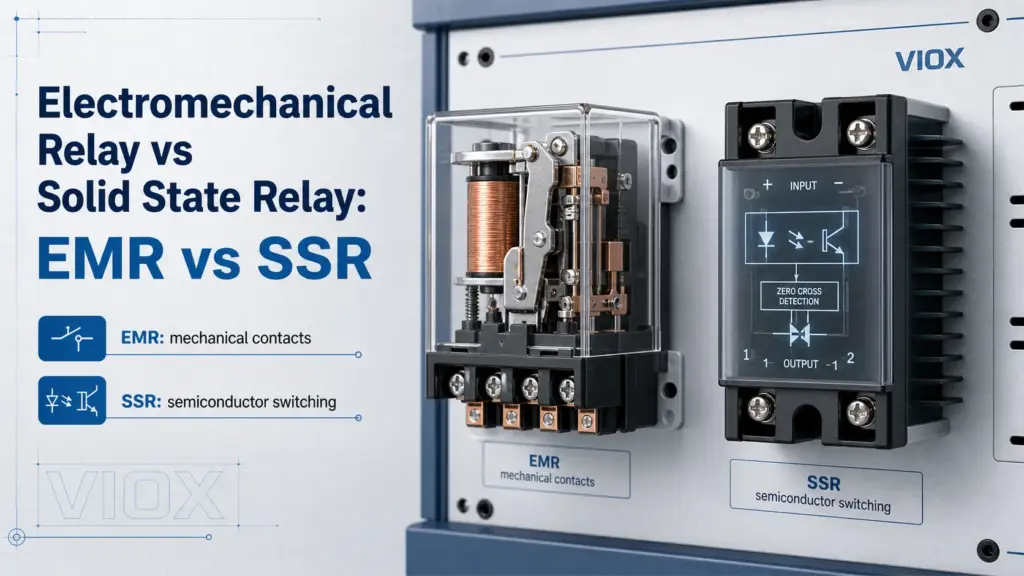
An electromechanical relay (EMR) switches a circuit by using an electromagnetic coil to move physical contacts. A solid state relay (SSR) switches a circuit electronically by using semiconductor devices such as TRIACs, thyristors, MOSFETs, or IGBTs, usually with optical isolation between the input and output.
Neither type is universally better. An EMR is often the better choice when you need very low off-state leakage, visible contact behavior, broad AC/DC flexibility, and better tolerance of short overloads. An SSR is usually better when you need silent operation, very high switching frequency, no contact bounce, and long life in repetitive switching applications such as heater control.
If you need basic SSR background first, see Understanding Solid State Relays. This article focuses on the selection decision between EMR and SSR.
From a standards perspective, the right framework depends on the device and application. Electromechanical contactors and motor starters are commonly discussed under IEC 60947-4-1; control circuit devices and switching elements are associated with IEC 60947-5-1; semiconductor motor controllers and starters are covered by IEC 60947-4-2; and AC semiconductor controllers/contactors for non-motor loads are covered by IEC 60947-4-3. In North American industrial panels, UL 508 and related product/listing requirements may also be relevant. Always use the standard and rating stated on the actual product datasheet.
EMR vs SSR Quick Comparison Table
| Czynnik wyboru | Electromechanical relay (EMR) | Solid state relay (SSR) |
|---|---|---|
| Switching method | Mechanical contacts moved by an electromagnetic coil | Semiconductor output device controlled electronically |
| Moving parts | TAK | NIE |
| Switching speed | Slower, typically limited by mechanical motion | Faster, often microsecond-to-millisecond class depending on design |
| Audible noise | Słyszalne kliknięcie | Cichy |
| Contact bounce | Możliwe | No mechanical bounce |
| Off-state leakage | Nearly zero through open contacts | Has off-state leakage current |
| On-state loss | Very low contact resistance when healthy | Voltage drop or on-resistance creates heat |
| Rozpraszanie ciepła | Usually lower in low-duty switching | Often needs derating and heat sinking |
| Surge/inrush tolerance | Often more tolerant of short overloads | More sensitive to overvoltage and overcurrent |
| Load compatibility | Flexible, if contact rating matches AC/DC and load type | Must match AC output, DC output, load type, and heat design carefully |
| Izolacja elektryczna | Coil-to-contact isolation | Optical or transformer isolation is common |
| Failure modes | Contact wear, contact welding, coil failure | Often fails short when semiconductor is damaged |
| Najlepsze dopasowanie | General control, interlocking, low-frequency switching | Frequent switching, silent control, heater/PID applications |
What Is an Electromechanical Relay?
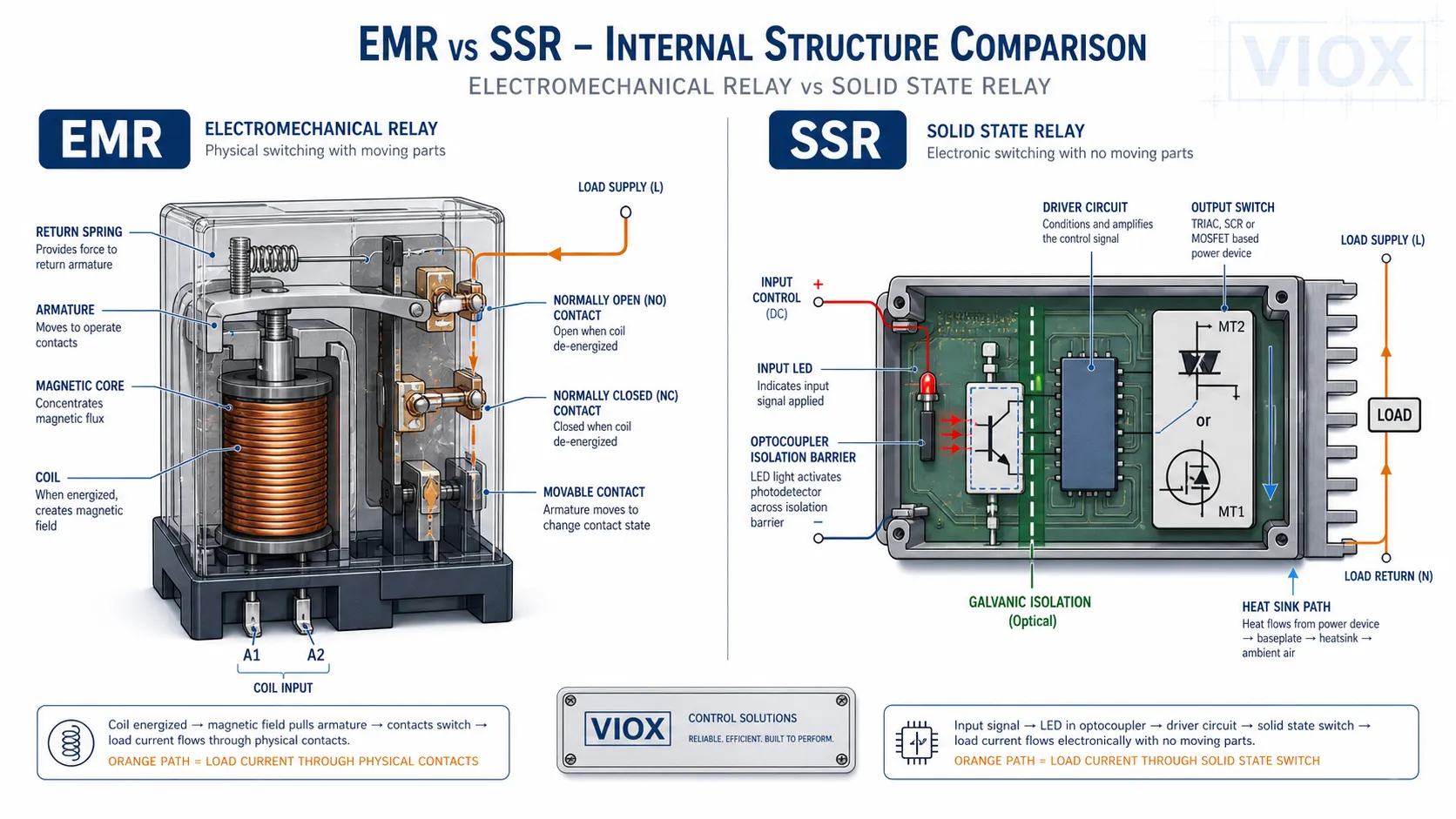
An electromechanical relay is an electrically operated switch. Its input side is a coil. When the coil is energized, it creates a magnetic field that pulls an armature and changes the state of one or more contacts. Contacts may be normally open (NO), normally closed (NC), or changeover contacts.
This simple mechanical action gives EMRs several practical strengths:
- open contacts provide very low leakage current
- the output circuit is physically separated from the coil circuit
- one relay can offer multiple contact forms
- AC and DC loads can often be switched by the same contact set if the rating is suitable
- technicians can often hear or feel the relay operating during troubleshooting
But the same mechanical design also creates limits. Contacts wear, bounce, arc, oxidize, and may weld under overload or inductive switching. The coil consumes power and may generate heat. Switching speed is limited by moving parts.
For general relay context, see Contactors vs Relays.
What Is a Solid State Relay?
A solid state relay performs the same basic switching function without mechanical contacts. The input signal drives an internal isolation stage, commonly optical coupling, and the output semiconductor switches the load.
Common SSR output technologies include:
- TRIAC output for AC loads
- SCR / thyristor output for AC loads, often in higher-power SSRs
- MOSFET output for DC loads or low-voltage switching
- IGBT output in some higher-voltage DC or power-control applications
Because there are no moving contacts, SSRs are silent and do not suffer from mechanical contact bounce. They are attractive for frequent switching applications, especially where a mechanical relay would wear out quickly.
However, an SSR is not a perfect electronic version of an EMR. It has off-state leakage current, on-state heat loss, surge limitations, and stricter load-type requirements. SSR selection is closer to selecting a power semiconductor than selecting a simple contact.
How EMR and SSR Work Differently
EMR switching path
In an EMR, the load current flows through physical metal contacts. When the contacts are open, the air gap provides separation. When the contacts close, current flows through the contact surfaces.
This gives an EMR a very clean off-state, but it also means the contacts absorb switching stress. Inductive loads such as coils, solenoids, small motors, and contactor coils can generate arcs and voltage transients when switched.
SSR switching path
In an SSR, the load current flows through a semiconductor device. The output never becomes a mechanical air gap. When off, the semiconductor blocks current but still allows a small leakage current. When on, the semiconductor has voltage drop or resistance, producing heat.
For AC SSRs, zero-cross types switch near the AC waveform zero crossing, which helps reduce electrical noise for resistive loads. Random-turn-on SSRs switch without waiting for zero crossing and are used where phase control or precise timing is needed. For DC SSRs, MOSFET-based designs are common, and polarity or bidirectional blocking must be checked carefully.
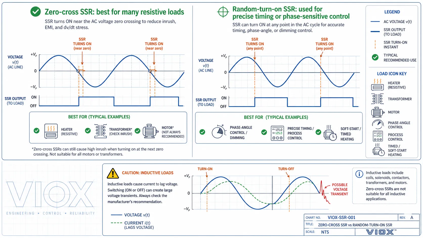
Zero-cross switching is useful, but it is not a universal advantage. For highly inductive loads such as transformers, large coils, or some motor-related circuits, current and voltage are not in phase. A zero-cross SSR selected only because it is “quieter” may create unexpected inrush, turn-on stress, or poor switching behavior. For inductive loads, check whether the manufacturer recommends zero-cross, random-turn-on, snubber networks, surge suppression, or a different switching device.
Advantages of Electromechanical Relays
1. Very low off-state leakage
When an EMR contact is open and healthy, the load side is physically separated. This makes EMRs useful where leakage current would cause problems, such as small pilot lamps, PLC inputs, high-impedance circuits, or loads that must be truly de-energized.
2. Good short overload tolerance
Mechanical contacts can often tolerate short inrush or surge events better than an undersized semiconductor output. This does not mean EMRs can ignore contact ratings, but it explains why EMRs are still common in general control circuits.
3. Flexible contact forms
EMRs can provide SPST, SPDT, DPDT, and multi-pole contacts. A single coil can switch multiple isolated circuits, which is useful for interlocking, status feedback, and mixed-voltage control.
4. Easy field troubleshooting
Technicians can often hear the click, measure coil voltage, and test contact continuity. This makes EMRs straightforward in many maintenance environments.
Disadvantages of Electromechanical Relays
1. Contact wear and arcing
Each operation creates mechanical and electrical stress. Switching inductive loads without proper suppression can cause contact pitting, carbon buildup, or contact welding.
2. Contact bounce
When contacts close, they may bounce briefly before settling. This can matter in counting, pulse, or logic circuits.
3. Limited switching frequency
For high-frequency switching, the mechanical parts become the limiting factor. Repeated operation also reduces mechanical and electrical life.
4. Audible noise
The click is useful for troubleshooting but undesirable in silent equipment, offices, laboratories, or noise-sensitive machines.
Advantages of Solid State Relays
1. No mechanical wear
An SSR has no moving contacts. In frequent switching applications, this is often the strongest reason to choose SSR.
2. Fast and silent switching
SSR switching is electronic, silent, and bounce-free. This is useful in heater control, semiconductor equipment, packaging machines, and applications with frequent on/off cycles.
3. Good fit for PID heater control
Temperature controllers often switch heaters many times per minute. An EMR may wear quickly in this role, while an appropriately heat-sinked SSR can handle frequent cycling.
4. Lower input drive current in many control systems
Many SSR inputs can be driven directly by low-power control outputs, although the required input voltage and current must still match the controller.
Disadvantages of Solid State Relays
1. Off-state leakage current
An SSR is not a perfect open contact. It has leakage current in the off-state. This can keep small loads glowing, confuse high-impedance inputs, or create a measurable voltage on the load side even when the SSR is off.
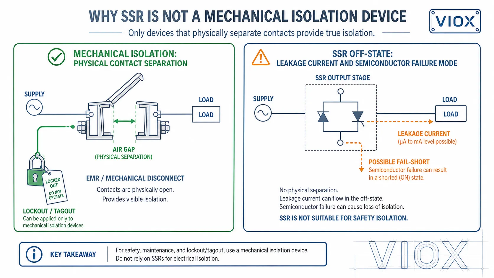
If a load must be fully isolated with near-zero leakage, an EMR, contactor, or mechanical disconnect may be required.
2. Heat generation and derating
SSRs dissipate heat during operation. AC SSRs typically have output voltage drop, while DC MOSFET SSRs have on-resistance. At higher current, this heat becomes a major design issue.
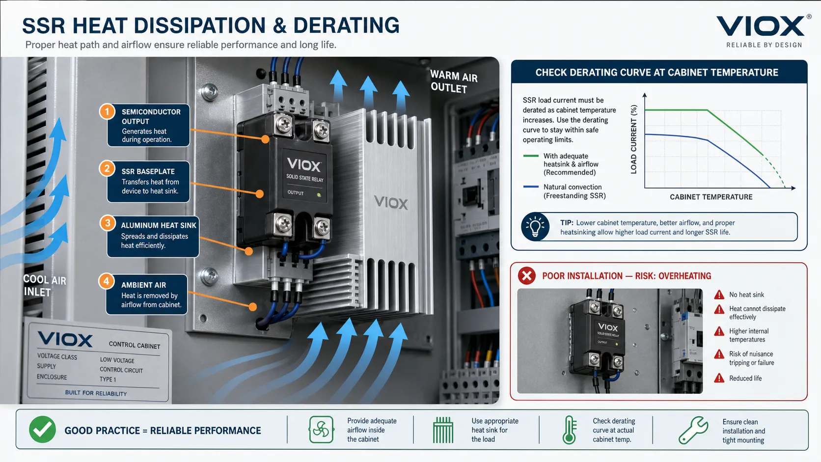
This is why SSR datasheets include heat sink, thermal resistance, ambient temperature, and derating curves. Mounting an SSR without proper heat dissipation is one of the most common causes of premature failure.
3. Surge and short-circuit sensitivity
Semiconductors can fail quickly under overvoltage, overcurrent, or high inrush conditions. Proper fuse coordination, surge suppression, and load matching are essential.
4. Failure often appears as a short
A damaged SSR output device may fail shorted. In practical terms, the load may remain energized even when the input command is off. For safety-related isolation, SSRs should not be treated as a substitute for mechanical isolation unless the complete safety architecture is designed and approved for that purpose.
In machinery control panels, standards such as IEC/EN 60204-1 focus heavily on proper supply disconnecting, prevention of unexpected start, protective bonding, and verification. A semiconductor output can be part of a control function, but it should not be treated as the sole electrical isolation device for lockout, maintenance, or personnel safety. When isolation is required, use a properly rated mechanical disconnecting or isolating device in the safety architecture.
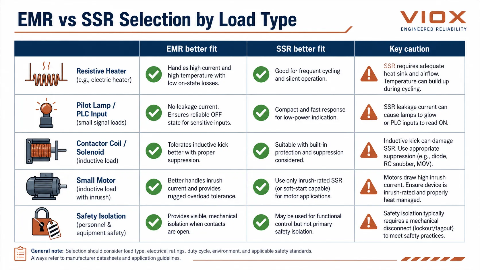
Load Type Matters More Than the Relay Type
The correct relay depends heavily on the load.
| Rodzaj obciążenia | EMR fit | SSR fit | Uwaga dotycząca doboru |
|---|---|---|---|
| Grzałka rezystancyjna | Dobry | Excellent for frequent cycling | SSR often preferred for PID temperature control |
| Pilot lamp or small signal load | Dobry | May be affected by leakage current | Check minimum load and leakage |
| Contactor coil / solenoid | Good with suppression | Possible, but output type and surge protection matter | Inductive kick must be controlled |
| Small motor | Possible if rated | Use carefully; inrush and inductive behavior matter | Consider contactor or motor starter for power circuits |
| PLC input switching | Dobry | Possible, but leakage may cause false signal | Match input type and threshold |
| Przełączanie z wysoką częstotliwością | Słaba do umiarkowanej | Silna pozycja | SSR avoids mechanical wear |
| Izolacja bezpieczeństwa | Mechanical device usually preferred | Not normally used alone | SSR leakage and fail-short mode must be considered |
If the relay is driving contactor coils, solenoids, or motor-control auxiliaries, suppression and contact duty become part of the selection, not an afterthought. VIOX’s motor-control guide explains how contactors, overload relays, and protective devices divide the job in a motor circuit: Jak dobrać styczniki, przekaźniki przeciążeniowe i wyłączniki silnikowe do zasilania silników. For coil transient protection, see Jak dobrać odpowiedni ogranicznik przepięć do styczników.
Standards and Ratings to Check Before Comparing EMR and SSR
Standards do not simply say “EMR is better” or “SSR is better.” They define how a device is tested, marked, and applied. The practical point is to compare the relay under the correct device family and load duty.
| Obszar | Relevant standard family or framework | Dlaczego to ma znaczenie |
|---|---|---|
| Electromechanical contactors and motor starters | IEC 60947-4-1 | Motor and contactor duty differs from simple resistive switching |
| Control relays and control circuit devices | IEC 60947-5-1 | Helps define control-circuit switching behavior and ratings |
| Semiconductor motor controllers and starters | IEC 60947-4-2 | Relevant when semiconductor devices control AC motor circuits |
| Semiconductor controllers/contactors for non-motor AC loads | IEC 60947-4-3 | Relevant for SSR-like power control of heaters and other AC loads |
| Machinery electrical equipment | IEC/EN 60204-1 | Important for supply disconnecting, safety isolation, and prevention of unexpected start |
| North American industrial control equipment | UL 508 and related listing requirements | Important for panel approval and component suitability in UL-oriented projects |
For buyers, the lesson is simple: compare the printed relay rating with the real load category. A relay that looks suitable by current alone may be unsuitable once switching duty, heat, leakage, short-circuit protection, or safety isolation is considered.
AC SSR vs DC SSR: Do Not Mix Them
One of the most common SSR selection mistakes is assuming that an SSR output is universal.
An AC SSR often uses TRIAC or SCR output devices. It is designed for AC loads and may rely on the AC waveform crossing zero to turn off. It is not suitable for DC load switching unless the datasheet explicitly says so.
A DC SSR often uses MOSFETs or IGBTs. It must be selected for DC voltage, current, polarity, and sometimes bidirectional blocking. Some DC SSRs are polarity-sensitive; others use back-to-back MOSFET arrangements for bidirectional blocking.
The label “SSR” only tells you the switching technology. It does not tell you whether the output is suitable for AC, DC, resistive loads, inductive loads, or motor loads.
Failure Modes: What Maintenance Teams Should Expect
| Objaw | EMR likely cause | SSR likely cause |
|---|---|---|
| Load stays on when command is off | Zespawane styki | Output semiconductor failed short, leakage confusing small load |
| Load does not turn on | Coil failure, contact damage, broken mechanism | Input circuit failure, output semiconductor open, thermal damage |
| Przerywana praca | Contact oxidation, weak coil voltage, vibration | Overtemperature, marginal input signal, transient damage |
| Control signal is present but output unstable | Contact bounce or mechanical chatter | Wrong SSR type, leakage, heat, or load incompatibility |
| Device runs hot | Coil or overloaded contact issue | Undersized SSR, missing heat sink, poor derating |
This field view is important because replacing an EMR with an SSR can change the failure behavior of the machine. The SSR may solve mechanical wear but introduce leakage or heat problems.
When Should You Choose an EMR?
Choose an electromechanical relay when:
- switching frequency is low or moderate
- off-state leakage must be nearly zero
- multiple isolated contacts are needed
- the load may involve short inrush or surge events
- field technicians need easy continuity testing
- cost sensitivity is high
- the circuit requires a familiar NO/NC/changeover contact behavior
EMRs are still strong choices for general control panels, interlocking, signaling, alarm circuits, and many timer relay outputs. For timing applications, see Relay vs Timer oraz How to Choose a Timer Relay.
When Should You Choose an SSR?
Choose a solid state relay when:
- switching frequency is high
- silent operation is required
- contact bounce cannot be tolerated
- the load is mainly resistive, such as heaters
- the control system uses frequent on/off cycling
- long mechanical life is more important than lowest off-state leakage
- proper heat sinking and protection can be designed into the panel
SSR selection should always include thermal calculation, load type, inrush current, leakage current, output type, surge protection, and short-circuit protection.
Common EMR vs SSR Selection Mistakes
Mistake 1: Choosing SSR because it sounds more advanced
SSR is not automatically better. If the application needs true open contacts, high surge tolerance, or simple field testing, EMR may be more practical.
Mistake 2: Ignoring SSR leakage current
Leakage current can keep small lamps glowing or cause PLC inputs to read incorrectly. Always compare SSR leakage current with the load or input threshold.
Mistake 3: Forgetting SSR heat dissipation
An SSR that is electrically rated for the current may still fail if it is mounted without the required heat sink, airflow, or derating.
In one common panel-builder scenario, an SSR that works during a short bench test fails later inside a compact cabinet because the enclosure temperature is much higher than the lab bench. The nameplate current rating was not the real problem; the missing derating check was. For heater control panels, always read the SSR derating curve at the expected cabinet temperature and verify the heat sink mounting surface.
Mistake 4: Using EMR contacts for frequent heater cycling
A mechanical relay used for rapid temperature control may wear quickly. SSR is often better for frequent heater switching if the thermal design is correct.
Mistake 5: Switching inductive loads without suppression
Both EMRs and SSRs need protection from inductive transients. EMRs may suffer contact arcing; SSRs may suffer semiconductor overvoltage.
This is especially important when replacing an EMR with an SSR. The old relay contact may have tolerated occasional coil kickback or inrush for years; the new semiconductor output may fail much faster if the same transient energy is not controlled.
Mistake 6: Treating SSR as a safety isolation device
An SSR has leakage current and may fail short. If personnel safety or maintenance isolation is required, use a properly rated mechanical isolation device or safety architecture.
Mistake 7: Using zero-cross SSRs for the wrong load
Zero-cross SSRs are often excellent for resistive heaters, but they are not automatically the right choice for transformers, large inductive loads, or phase-sensitive applications. When the load current lags the voltage, the switching behavior can be different from what the simple “turn on at voltage zero” explanation suggests.
Lista kontrolna wyboru
Before choosing EMR or SSR, check:
| Sprawdź | Dlaczego to ma znaczenie |
|---|---|
| Rodzaj obciążenia | Resistive, inductive, capacitive, motor, heater, signal |
| AC or DC output | SSR output type must match the load current type |
| Load current and inrush | Determines contact rating or semiconductor stress |
| Częstotliwość przełączania | High frequency favors SSR; low frequency often suits EMR |
| Leakage current tolerance | Important for small loads and PLC inputs |
| Rozpraszanie ciepła | Critical for SSR current rating and life |
| Surge suppression | Needed for coils, solenoids, motors, and transient-prone circuits |
| Failure mode requirement | EMR and SSR fail differently |
| Formularz kontaktowy | EMR can provide NO/NC/changeover contacts easily |
| Izolacja bezpieczeństwa | Usually requires a mechanical isolation device |
FAQ
Is an SSR better than an electromechanical relay?
Not always. SSRs are better for silent, fast, frequent switching. EMRs are often better when you need near-zero leakage, multiple contact forms, surge tolerance, or simple troubleshooting.
Does an SSR completely turn off the load?
Not in the same way as an open mechanical contact. SSRs have off-state leakage current, so small loads or high-impedance inputs may still see voltage or current.
Why does an SSR need a heat sink?
An SSR generates heat because its semiconductor output has voltage drop or resistance. At higher current, that heat must be removed through a heat sink, mounting plate, or proper derating.
Can I replace an EMR with an SSR directly?
Only after checking output type, load current, inrush current, leakage current, heat dissipation, control voltage, and failure mode. A pin-compatible or voltage-compatible device may still behave differently.
Which relay is better for heater control?
For frequent heater switching, SSR is often preferred because it has no contact wear and can switch silently. Heat sinking and load current derating must still be correct.
Which relay is better for PLC input signals?
EMR contacts are often simpler when the input must see a true dry contact. SSR outputs can work, but leakage current and input threshold must be checked.
What happens when an SSR fails?
Many SSR failures appear as a shorted output, meaning the load may stay on. This is why SSRs should not be used as the only isolation device for maintenance or safety-critical shutoff.
Can SSRs switch motors?
Some SSRs can switch motor loads if specifically rated for that duty, but motor inrush and inductive stress must be considered. For many motor circuits, contactors, overload relays, motor starters, or dedicated soft starters are more appropriate.
Podsumowanie
The EMR vs SSR decision is not a technology upgrade question. It is an application-fit question.
Wybierać EMR when you need low leakage, mechanical contacts, multiple contact forms, surge tolerance, and easy field troubleshooting.
Wybierać SSR when you need silent operation, high switching frequency, no contact bounce, and long life in repetitive switching applications, especially resistive heater control.
For VIOX control panel applications, the safest selection method is to start with the load type, switching frequency, leakage tolerance, thermal design, and failure mode. Then choose EMR or SSR based on the actual circuit behavior, not the assumption that one technology is always better.
Wykorzystane źródła
- Relay operating principle and electromechanical relay construction
- Solid-state relay operation, characteristics, zero-cross switching, and parameters
- Static relay overview and contrast with electromechanical relays
- IEC 60204-1 scope and machinery electrical equipment context
- IEC utilization categories and IEC 60947 standard family context
