ໃນໜ້ານີ້
ການບຳລຸງຮັກສາສະວິດປ່ຽນແຫຼ່ງຈ່າຍໄຟອັດຕະໂນມັດ (ATS) ເປັນຂະບວນການສະເພາະຂອງອຸປະກອນນັ້ນໆ ບໍ່ແມ່ນການທົດສອບປະຈຳປີແບບທົ່ວໄປ. ໂຄງການທີ່ສາມາດອ້າງອີງໄດ້ຈະແຍກການສັງເກດການແບບອອນລາຍຕາມປົກກະຕິ, ການບໍລິການແບບຕັດໄຟຕາມແຜນ, ການທົດສອບການໂອນຍ້າຍການເຮັດວຽກ ແລະ ການທົດສອບທາງໄຟຟ້າສະເພາະທາງອອກຈາກກັນ. ມັນຕ້ອງປະຕິບັດຕາມຄຳແນະນຳຂອງ ATS ຢ່າງເຄັ່ງຄັດ ແລະ ໂຄງການຄວາມປອດໄພທາງໄຟຟ້າຂອງສະຖານທີ່, ບັນທຶກສະພາບທີ່ພົບເຫັນ, ແລະ ກວດສອບວ່າລະບົບທັງໝົດໄດ້ຖືກຟື້ນຟູໃຫ້ກັບຄືນສູ່ການເຮັດວຽກແບບອັດຕະໂນມັດແລ້ວ.
ລຳດັບທີ່ຈຳເປັນມີດັ່ງນີ້:
ກະກຽມ ແລະ ບັນທຶກ → ແຍກແຫຼ່ງຈ່າຍໄຟໃນຈຸດທີ່ຕ້ອງການ → ກວດກາ ແລະ ບໍລິການ → ທົດສອບການເຮັດວຽກ → ຟື້ນຟູ ແລະ ບັນທຶກ
| ລະດັບການບຳລຸງຮັກສາ | ຈຸດປະສົງຫຼັກ | ຫຼັກຖານທົ່ວໄປ | ຂອບເຂດທີ່ສຳຄັນ |
|---|---|---|---|
| ການສັງເກດການແບບອອນລາຍຕາມປົກກະຕິ | ກວດຫາສະຖານະທີ່ເບິ່ງເຫັນໄດ້, ສັນຍານເຕືອນ, ການປ່ຽນແປງດ້ານສະພາບແວດລ້ອມ ຫຼື ການເຮັດວຽກ | ສະຖານະຂອງຕົວຄວບຄຸມ, ບັນທຶກເຫດການ, ການແຈ້ງເຕືອນ, ສະພາບຂອງຕູ້ຄອນໂທລ | ຫ້າມເປີດຊ່ອງທີ່ມີການປ້ອງກັນ ຫຼື ເຂົ້າໃກ້ສ່ວນທີ່ມີໄຟຟ້າໂດຍບໍ່ມີການອະນຸຍາດໃຫ້ປະຕິບັດງານໃນຂະນະທີ່ມີໄຟຟ້າ |
| ການບຳລຸງຮັກສາຕາມແຜນໃນສະພາບທີ່ຕັດໄຟຟ້າ | ກວດສອບ, ເຮັດຄວາມສະອາດ ແລະ ບຳລຸງຮັກສາສ່ວນທີ່ສາມາດເຂົ້າເຖິງໄດ້ | ຮູບພາບສະພາບເດີມ, ສະພາບທາງກົນຈັກ, ສະພາບການເຊື່ອມຕໍ່, ບັນທຶກການບໍລິການຕາມທີ່ຜູ້ຜະລິດກຳນົດ | ແຍກແຫຼ່ງພະລັງງານ ແລະ ແຫຼ່ງຄວບຄຸມທຸກຢ່າງທີ່ເປັນໄປໄດ້, ລວມທັງລະບົບເລີ່ມຕົ້ນການເຮັດວຽກອັດຕະໂນມັດຂອງເຄື່ອງກຳເນີດໄຟຟ້າ |
| ການທົດສອບການໂອນຍ້າຍການເຮັດວຽກ | ພິສູດການຕອບສະໜອງຂອງລະບົບຕັ້ງແຕ່ການກວດຈັບແຫຼ່ງຈ່າຍໄຟ ຈົນເຖິງການໂອນຍ້າຍ, ການໂອນຍ້າຍກັບ ແລະ ການເຮັດໃຫ້ເຢັນລົງ | ລຳດັບເວລາ, ການວັດແທກແຫຼ່ງຈ່າຍໄຟ, ຕຳແໜ່ງ, ສັນຍານເຕືອນ ແລະ ສະຖານະ AUTO ສຸດທ້າຍ | ໃຫ້ໃຊ້ຟັງຊັນການທົດສອບທີ່ໄດ້ຮັບການອະນຸມັດ ຫຼື ວິທີການທີ່ກຳນົດໄວ້—ຫ້າມໃຊ້ວິທີການຕັດໄຟແບບສົດໆທີ່ບໍ່ໄດ້ມາດຕະຖານ |
| ການທົດສອບທາງໄຟຟ້າສະເພາະທາງ | ກວດສອບສະພາບ ຫຼື ປະຕິບັດຕາມແຜນການບຳລຸງຮັກສາ/ການທົດສອບທີ່ກຳນົດໄວ້ | ການຖ່າຍພາບຄວາມຮ້ອນ (Thermography), ຄວາມຕ້ານທານຂອງຂົ້ວຕໍ່, ຄວາມຕ້ານທານຂອງສນວນ ຫຼື ຜົນການທົດສອບອື່ນໆທີ່ໄດ້ຮັບການອະນຸມັດ | ໃຫ້ປະຕິບັດເມື່ອມີຂັ້ນຕອນການເຮັດວຽກຂອງອຸປະກອນ, ການຕັ້ງຄ່າການທົດສອບ ແລະ ເກນການຍອມຮັບທີ່ຊັດເຈນແລ້ວເທົ່ານັ້ນ |
ຂອບເຂດຄວາມປອດໄພ: ATS ອາດມີພະລັງງານອັນຕະລາຍຈາກແຫຼ່ງຈ່າຍໄຟປົກກະຕິ ແລະ ແຫຼ່ງຈ່າຍໄຟສຳຮອງໃນເວລາเดียวกัน. ໄຟຄວບຄຸມ, ວົງຈອນການເລີ່ມຕົ້ນຂອງເຄື່ອງປັ່ນໄຟ ແລະ ການສັ່ງງານຈາກໄລຍະໄກອາດຍັງເຮັດວຽກຢູ່ຫຼັງຈາກແຫຼ່ງຈ່າຍໄຟໜຶ່ງຖືກຕັດອອກ. ການກວດສອບພາຍໃນ, ການແຍກວົງຈອນ, ການທົດສອບ ແລະ ການຟື້ນຟູລະບົບ ຕ້ອງດຳເນີນການໂດຍຜູ້ຊ່ຽວຊານທີ່ເຮັດວຽກພາຍໃຕ້ຂັ້ນຕອນຂອງສະຖານທີ່, ຄຳແນະນຳຂອງອຸປະກອນ, ການຄວບຄຸມການເກີດໄຟຟ້າວູບ (arc-flash) ແລະ ໂຄງການລັອກ/ປ້າຍເຕືອນ (lockout/tagout). ບົດຄວາມນີ້ເປັນພຽງໂຄງຮ່າງການວາງແຜນ ແລະ ການບັນທຶກຂໍ້ມູນເທົ່ານັ້ນ, ບໍ່ແມ່ນການອະນຸຍາດໃຫ້ເຮັດວຽກກັບອຸປະກອນທີ່ມີໄຟຟ້າ.
ສິ່ງທີ່ຕ້ອງຮູ້ກ່ອນເລີ່ມການບຳລຸງຮັກສາ ATS
ຊຸດວຽກຄວນລະບຸອຸປະກອນທີ່ແນ່ນອນ ແລະ ຜົນກະທົບຕໍ່ລະບົບໄຟຟ້າເມື່ອຕັດອຸປະກອນນັ້ນອອກຈາກການໃຊ້ງານປົກກະຕິ. ຢ່າເລີ່ມຕົ້ນດ້ວຍລາຍການກວດສອບທົ່ວໄປ ແລ້ວໄປຫາວິທີການຈັດການແຫຼ່ງຈ່າຍໄຟໃນລະຫວ່າງທີ່ໄຟດັບ.
ບັນທຶກຢ່າງໜ້ອຍ:
- ຜູ້ຜະລິດ ATS, ຮຸ່ນ, ເລກລຳດັບ ແລະ ເວີຊັນຂອງຕົວຄວບຄຸມ;
- ແຮງດັນໄຟຟ້າ, ກະແສໄຟຟ້າ, ຄວາມຖີ່ ແລະ ຈຳນວນຂົ້ວທີ່ກຳນົດ;
- ເອກະລັກຂອງແຫຼ່ງຈ່າຍໄຟປົກກະຕິ ແລະ ແຫຼ່ງຈ່າຍໄຟສຳຮອງ;
- ການຈັດວາງແບບສະວິດນິວທຣອນ (switched-neutral) ຫຼື ນິວທຣອນຮ່ວມ (solid-neutral);
- ການປ່ຽນຜ່ານແບບເປີດ, ແບບໜ່ວງເວລາ, ແບບເຟສດຽວກັນ ຫຼື ແບບປິດ, ຕາມຄວາມເໝາະສົມ;
- ສະຖາປັດຕະຍະກຳການສະຫຼັບແບບ PC-class ຫຼື CB-class ແລະ ອຸປະກອນປ້ອງກັນທີ່ກ່ຽວຂ້ອງ;
- ວິທີການໂຕ້ຕອບການເລີ່ມຕົ້ນຂອງເຄື່ອງປັ່ນໄຟ ແລະ ແຫຼ່ງພະລັງງານຄວບຄຸມ;
- ຄວາມສາມາດໃນການບາຍພາດ/ແຍກວົງຈອນ, ຖ້າມີຕິດຕັ້ງ;
- ແຜນວາດເສັ້ນດຽວທີ່ໄດ້ຮັບການອະນຸມັດ, ແຜນວາດຄວບຄຸມ ແລະ ຄຳແນະນຳຜະລິດຕະພັນທີ່ຊັດເຈນ;
- ບັນທຶກການຕັ້ງຄ່າຫຼ້າສຸດ, ບັນທຶກເຫດການ, ຜົນການທົດສອບກ່ອນໜ້ານີ້ ແລະ ຂໍ້ບົກຜ່ອງທີ່ຍັງບໍ່ທັນໄດ້ແກ້ໄຂ;
- ໂຫຼດທີ່ໄດ້ຮັບຜົນກະທົບ, ການຂັດຂ້ອງທີ່ຍອມຮັບໄດ້ ແລະ ອຳນາດການຟື້ນຟູລະບົບ;
- ການລະບຸອຸປະກອນທົດສອບທີ່ໄດ້ຮັບການປັບທຽບ ແລະ ໃບສະເໜີວິທີການທີ່ໄດ້ຮັບການອະນຸມັດ.
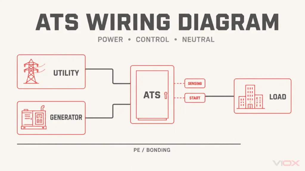
ໄດ້ ເອກະສານອ້າງອີງແຜນວາດການຕໍ່ສາຍໄຟ ATS ອະທິບາຍເຖິງການແຍກສ່ວນທົ່ວໄປລະຫວ່າງຂົ້ວຕໍ່ໄຟຟ້າ, ການກວດຈັບ, ໄຟລ້ຽງຕົວຄວບຄຸມ, ໜ້າສຳຜັດເລີ່ມຕົ້ນເຄື່ອງກຳເນີດໄຟຟ້າ, ສາຍນິວທຣອນ ແລະ ສາຍດິນປ້ອງກັນ. ມັນບໍ່ໄດ້ໃຊ້ແທນຮູບແຕ້ມຂົ້ວຕໍ່ຂອງຮຸ່ນທີ່ເລືອກ. ສຳລັບແຫຼ່ງຈ່າຍ, ໂຫຼດ, ການເລືອກພິກັດ ແລະ ການປ້ອງກັນ, ໃຫ້ໃຊ້ ຄູ່ມືສະວິດໂອນຍ້າຍເຄື່ອງກຳເນີດໄຟຟ້າ.
ກຳນົດຂອບເຂດການບຳລຸງຮັກສາ ແລະ ເງື່ອນໄຂການຢຸດເຮັດວຽກ
ຜູ້ວາງແຜນການບຳລຸງຮັກສາຄວນຕັດສິນໃຈວ່າງານໃດສາມາດເຮັດວຽກຕໍ່ໄປໄດ້ໃນຂະນະທີ່ລະບົບຍັງເຮັດວຽກຢູ່ ແລະ ງານໃດທີ່ຕ້ອງການການຕັດໄຟ ຫຼື ເສັ້ນທາງບາຍພາດທີ່ອອກແບບໄວ້. ATS ມາດຕະຖານ ແລະ ATS ແບບບາຍພາດ-ໄອໂຊເລຊັນ ບໍ່ໄດ້ໃຫ້ຂອບເຂດການບຳລຸງຮັກສາທີ່ຄືກັນ. VIOX ຄູ່ມືສະວິດໂອນຍ້າຍແບບບາຍພາດ-ໄອໂຊເລຊັນ ອະທິບາຍເຖິງສິ່ງທີ່ເສັ້ນທາງບາຍພາດສາມາດຮັກສາໄວ້ໄດ້—ແລະ ສິ່ງໃດທີ່ສາມາດມີໄຟລ້ຽງຢູ່—ໃນຂະນະທີ່ກົນໄກການໂອນຍ້າຍຫຼັກຖືກແຍກອອກ.
ກຳນົດເງື່ອນໄຂການຢຸດເຮັດວຽກກ່ອນທີ່ຈະເປີດອຸປະກອນ. ຕົວຢ່າງລວມມີ:
- ແຜນວາດເສັ້ນດຽວ ຫຼື ການລະບຸແຫຼ່ງຈ່າຍໄຟບໍ່ກົງກັບການຕິດຕັ້ງ;
- ກວດພົບຕົວນຳທີ່ມີໄຟຟ້າ ຫຼື ແຫຼ່ງຄວບຄຸມທີ່ບໍ່ຄາດຄິດ;
- ບໍ່ສາມາດປ້ອງກັນເຄື່ອງກຳເນີດໄຟຟ້າຈາກການເລີ່ມເຮັດວຽກແບບອັດຕະໂນມັດ ຫຼື ທາງໄກໄດ້;
- ພົບຫຼັກຖານຂອງນ້ຳເຂົ້າ, ຄວາມຮ້ອນເກີນຢ່າງຮຸນແຮງ, ການເກີດປະກາຍໄຟ ຫຼື ເຫດການໄຟຟ້າລັດວົງຈອນ;
- ວິທີການທົດສອບທີ່ມີຢູ່ຂັດກັບຄຳແນະນຳຂອງຜູ້ຜະລິດ;
- ໂຫຼດທີ່ສຳຄັນບໍ່ສາມາດທົນຕໍ່ການຂັດຂ້ອງ ຫຼື ການໂອນຍ້າຍທີ່ສະເໜີໄວ້ໄດ້;
- ອຸປະກອນກັ້ນ, PPE, ອຸປະກອນທົດສອບ, ເຄື່ອງມືທີ່ໄດ້ຮັບການປັບທຽບ ຫຼື ບຸກຄະລາກອນທີ່ມີຄຸນວຸດທິທີ່ຈຳເປັນນັ້ນບໍ່ມີພ້ອມ.
ການພົບເຫັນເງື່ອນໄຂເຫຼົ່ານີ້ຢ່າງໃດຢ່າງໜຶ່ງ ບໍ່ໄດ້ໝາຍຄວາມວ່າການບຳລຸງຮັກສາລົ້ມເຫຼວ ແຕ່ມັນເປັນການຢຸດເຮັດວຽກແບບຄວບຄຸມ ເພື່ອປ້ອງກັນບໍ່ໃຫ້ແຜນການທີ່ບໍ່ສົມບູນກາຍເປັນອຸບັດຕິເຫດທາງໄຟຟ້າ.
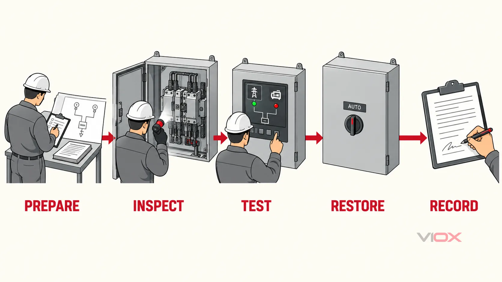
ຂັ້ນຕອນການບຳລຸງຮັກສາ ແລະ ການທົດສອບ ATS 5 ໄລຍະ
1. ກະກຽມລະບົບ ແລະ ບັນທຶກສະພາບທີ່ພົບເຫັນຕົວຈິງ
ເລີ່ມຕົ້ນດ້ວຍ ATS ໃນສະພາວະການເຮັດວຽກປົກກະຕິ ເວັ້ນເສຍແຕ່ວ່າຂັ້ນຕອນທີ່ໄດ້ຮັບການອະນຸມັດຈະລະບຸໄວ້ເປັນຢ່າງອື່ນ. ກ່ອນທີ່ຈະປັບປ່ຽນການຕັ້ງຄ່າ, ຕົວນຳ ຫຼື ກົນໄກຕ່າງໆ:
- ຢືນຢັນແຫຼ່ງຈ່າຍໄຟປົກກະຕິ, ແຫຼ່ງຈ່າຍໄຟສຳຮອງ, ໂຫຼດ ແລະ ຕຳແໜ່ງຂອງ ATS ໃນປັດຈຸບັນ.
- ບັນທຶກໂໝດຂອງຕົວຄວບຄຸມ, ສັນຍານສະແດງແຫຼ່ງຈ່າຍໄຟທີ່ພ້ອມໃຊ້ງານ, ສັນຍານເຕືອນທີ່ເຮັດວຽກຢູ່ ແລະ ຄ່າທີ່ສະແດງຜົນ.
- ຮັກສາບັນທຶກເຫດການ ແລະ ຕົວນັບການສັບປ່ຽນ ໃນກໍລະນີທີ່ຕົວຄວບຄຸມມີຟັງຊັນດັ່ງກ່າວ.
- ປຽບທຽບການຕັ້ງຄ່າຂອງຜູ້ໃຊ້, ການໜ່ວງເວລາ ແລະ ພາຣາມິເຕີການຍອມຮັບແຫຼ່ງຈ່າຍໄຟ ກັບບັນທຶກການຕັ້ງຄ່າທີ່ໄດ້ຮັບການອະນຸມັດ; ຢ່າຄາດເດົາວ່າຄ່າເລີ່ມຕົ້ນຈາກໂຮງງານແມ່ນຄ່າທີ່ໃຊ້ໃນໂຄງການ.
- ກວດສອບພາຍນອກເພື່ອຫາຄວາມເສຍຫາຍ, ການກັດກ່ອນ, ຄວາມຊຸ່ມ, ຊ່ອງລະບາຍອາກາດອຸດຕັນ, ການປົນເປື້ອນ, ຮາດແວທີ່ຫຼວມ ຫຼື ຮ່ອງຮອຍຂອງຄວາມຮ້ອນທີ່ຜິດປົກກະຕິ.
- ບັນທຶກກະແສໄຟຟ້າແຕ່ລະເຟສ ແລະ ສະພາວະການເຮັດວຽກ ຖ້າມີການວາງແຜນການຖ່າຍພາບຄວາມຮ້ອນ ຫຼື ການປຽບທຽບກ່ອນ/ຫຼັງ.
ຫຼັກຖານທີ່ຄາດຫວັງ: ບັນທຶກສະພາບເດີມທີ່ມີການປະທັບເວລາ ເຊິ່ງສະແດງເຖິງສະຖານະແຫຼ່ງຈ່າຍ, ຕຳແໜ່ງ ATS, ໂໝດຕົວຄວບຄຸມ, ສະຖານະການຕັ້ງຄ່າ, ສັນຍານເຕືອນ, ສະພາວະໂຫຼດ ແລະ ຂໍ້ບົກຜ່ອງທີ່ເຫັນໄດ້ຊັດເຈນ.
ເງື່ອນໄຂການຢຸດ: ສັນຍານເຕືອນທີ່ເຮັດວຽກຢູ່, ຮູບແບບຄວາມຮ້ອນທີ່ຜິດປົກກະຕິ, ຕູ້ໃສ່ອຸປະກອນທີ່ເສຍຫາຍ, ແຫຼ່ງຈ່າຍທີ່ບໍ່ສາມາດລະບຸໄດ້ ຫຼື ການປ່ຽນແປງການຕັ້ງຄ່າທີ່ບໍ່ສາມາດອະທິບາຍໄດ້ ຈະຕ້ອງໄດ້ຮັບການປະເມີນກ່ອນທີ່ລຳດັບການເຮັດວຽກທີ່ວາງແຜນໄວ້ຈະດຳເນີນຕໍ່ໄປ.
2. ກຳນົດສະພາວະການເຮັດວຽກທີ່ປອດໄພຕາມຄວາມຕ້ອງການ
ນຳໃຊ້ຂັ້ນຕອນການຄວບຄຸມພະລັງງານສະເພາະຂອງສະຖານທີ່ກັບທຸກແຫຼ່ງຈ່າຍທີ່ສາມາດປ່ອຍກະແສໄຟຟ້າເຂົ້າສູ່ເຂດເຮັດວຽກໄດ້. ຂຶ້ນຢູ່ກັບການອອກແບບ, ສິ່ງນັ້ນອາດລວມເຖິງແຫຼ່ງຈ່າຍປົກກະຕິ, ເຄື່ອງປັ່ນໄຟ ຫຼື ແຫຼ່ງຈ່າຍສຳຮອງ, ແຫຼ່ງຈ່າຍໄຟໃຫ້ຕົວຄວບຄຸມແຍກຕ່າງຫາກ, ແຫຼ່ງຈ່າຍໄຟໃຫ້ເຄື່ອງເຮັດຄວາມຮ້ອນພາຍໃນຕູ້, ພະລັງງານທີ່ເກັບໄວ້ ແລະ ວົງຈອນການເລີ່ມຕົ້ນ/ຄວບຄຸມໄລຍະໄກ.
ແຜນການເຮັດວຽກທີ່ປອດໄພຄວນກວມເອົາ:
- ການແຈ້ງເຕືອນ ແລະ ການໂອນຍ້າຍ ຫຼື ການປິດໂຫຼດທີ່ໄດ້ຮັບຜົນກະທົບ;
- ການປິດການໃຊ້ງານ ແລະ ການກວດສອບການເລີ່ມຕົ້ນເຮັດວຽກແບບອັດຕະໂນມັດ/ທາງໄກຂອງເຄື່ອງກຳເນີດໄຟຟ້າ ຕາມທີ່ຂັ້ນຕອນກຳນົດ;
- ການເປີດ ແລະ ການລັອກອຸປະກອນຕັດແຍກພະລັງງານທີ່ກຳນົດໄວ້;
- ການປ່ອຍ ຫຼື ການຍຶດພະລັງງານກົນຈັກທີ່ສະສົມໄວ້ ໃນກໍລະນີທີ່ສາມາດນຳໃຊ້ໄດ້;
- ການກວດສອບການຕັດແຍກ ແລະ ການບໍ່ມີແຮງດັນໄຟຟ້າ ໂດຍໃຊ້ເຄື່ອງມື ແລະ ວິທີການທີ່ໄດ້ຮັບການອະນຸມັດ;
- ການຄວບຄຸມເສັ້ນທາງການໄຫຼກັບຂອງກະແສໄຟຟ້າ (backfeed), ການສະໜອງພະລັງງານເສີມ ແລະ ການປະຕິບັດງານທີ່ສັ່ງການຈາກທາງໄກ;
- ເງື່ອນໄຂທີ່ອະນຸຍາດໃຫ້ມີການຈ່າຍໄຟຊົ່ວຄາວເພື່ອການທົດສອບການເຮັດວຽກ.
ຄຳແນະນຳກ່ຽວກັບພະລັງງານອັນຕະລາຍຂອງ OSHA ເນັ້ນໜັກເຖິງຂັ້ນຕອນການຄວບຄຸມພະລັງງານທີ່ມີເອກະສານຢັ້ງຢືນ ແລະ ພະນັກງານທີ່ໄດ້ຮັບອະນຸຍາດ. ເມື່ອອຸປະກອນຕ້ອງໄດ້ຮັບການປ່ອຍກະແສໄຟຟ້າຊົ່ວຄາວເພື່ອການທົດສອບ ຫຼື ການຈັດວາງຕຳແໜ່ງ, OSHA ໄດ້ອະທິບາຍເຖິງລຳດັບການຄວບຄຸມ ເຊິ່ງລວມເຖິງການເກັບມ້ຽນເຄື່ອງມື ແລະ ວັດສະດຸ, ການຍ້າຍບຸກຄະລາກອນອອກຈາກພື້ນທີ່, ການປ່ອຍກະແສໄຟຟ້າແບບຄວບຄຸມ, ແລະ ການນຳໃຊ້ລະບົບຄວບຄຸມພະລັງງານຄືນໃໝ່ກ່ອນການບຳລຸງຮັກສາຕໍ່ໄປ.
ຫຼັກຖານທີ່ຄາດຫວັງ: ບັນທຶກການສະຫຼັບໄຟ/LOTO ທີ່ສຳເລັດສົມບູນ, ການກວດສອບຂອບເຂດພື້ນທີ່ເຮັດວຽກ ແລະ ການອະນຸຍາດໃຫ້ດຳເນີນການຕໍ່.
ເງື່ອນໄຂການຢຸດ: ຖ້າແຫຼ່ງພະລັງງານໃດໜຶ່ງ ຫຼື ການເຮັດວຽກແບບອັດຕະໂນມັດບໍ່ສາມາດຄວບຄຸມໄດ້ຢ່າງແນ່ນອນພາຍໃຕ້ຂັ້ນຕອນທີ່ໄດ້ຮັບການອະນຸມັດ, ຫ້າມເລີ່ມການບຳລຸງຮັກສາພາຍໃນ.
3. ກວດສອບ ແລະ ບຳລຸງຮັກສາ ATS ທີ່ຕັດກະແສໄຟຟ້າອອກແລ້ວ
ປະຕິບັດຕາມຄຳແນະນຳຂອງຜູ້ຜະລິດຢ່າງເຄັ່ງຄັດສຳລັບຝາປິດ, ສິ່ງກີດຂວາງ, ໜ້າສຳຜັດ, ກົນໄກ ແລະ ຊິ້ນສ່ວນທີ່ສາມາດບຳລຸງຮັກສາໄດ້. ການກວດສອບທີ່ມີປະສິດທິພາບຄວນແບ່ງອອກເປັນຫ້າໂຊນ ແທນທີ່ຈະຖືວ່າຕູ້ຄວບຄຸມເປັນລາຍການດຽວ.
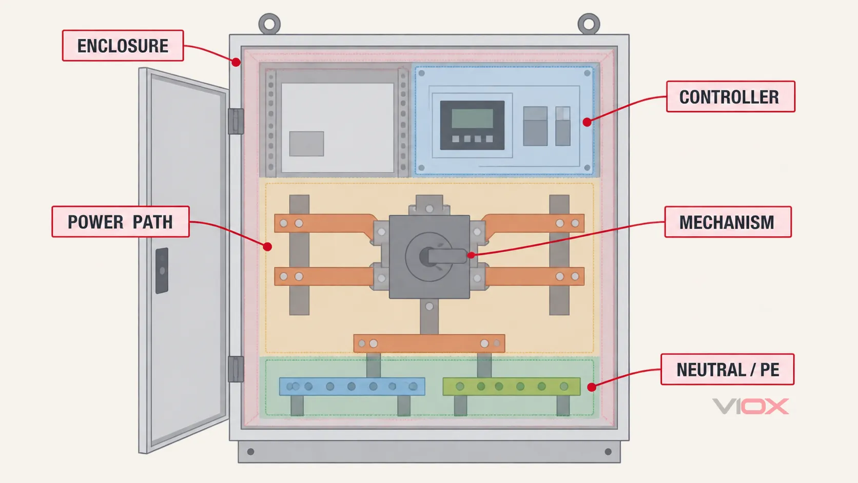
| ເຂດກວດກາ | ສິ່ງທີ່ຕ້ອງກວດສອບ | ຂອບເຂດການບັນທຶກ ຫຼື ການດຳເນີນການ |
|---|---|---|
| ຕູ້ຄວບຄຸມ ແລະ ສະພາບແວດລ້ອມການຕິດຕັ້ງ | ຄວາມຊຸ່ມ, ຝຸ່ນ, ການກັດກ່ອນ, ສັດຕູພືດ, ຕົວກອງ ຫຼື ການລະບາຍອາກາດ, ຊີລປະຕູ, ປ້າຍຊື່, ການຍຶດຕິດ ແລະ ໄລຍະຫ່າງ | ແກ້ໄຂສາເຫດທາງສະພາບແວດລ້ອມ; ວັດສະດຸ ແລະ ວິທີການທຳຄວາມສະອາດຕ້ອງສອດຄ່ອງກັບຄຳແນະນຳ |
| ເສັ້ນທາງພະລັງງານ | ຕົວນຳທີ່ສາມາດເຂົ້າເຖິງໄດ້, ຂົ້ວຕໍ່ສາຍ, ແຖບທອງແດງ (bus), ສະນວນ, ແຜ່ນກັ້ນ, ສະພາບຂອງຟິວ ແລະ ຮ່ອງຮອຍທີ່ເຫັນໄດ້ຊັດເຈນຂອງການຮ້ອນເກີນ ຫຼື ຄວາມຄຽດຈາກການເກີດຟອລ໌ດ | ຫ້າມຂັນອັດອຸປະກອນທີ່ມາຈາກໂຮງງານທັງໝົດຄືນໃໝ່ ຫຼື ໄປແຕະຕ້ອງຂໍ້ຕໍ່ທີ່ຜະນຶກໄວ້/ບໍ່ຕ້ອງການການບຳລຸງຮັກສາ |
| ກົນໄກການຖ່າຍໂອນ | ການຈັດວາງ, ການສຶກຫໍ້, ການຕິດຂັດ, ການເຊື່ອມຕໍ່, ສະປິງ, ລະບົບລັອກປ້ອງກັນ ແລະ ກົນໄກການເຮັດວຽກດ້ວຍມື ໃນກໍລະນີທີ່ຄຳແນະນຳອະນຸຍາດໃຫ້ມີການກວດສອບ | ໃຫ້ໃສ່ນ້ຳມັນຫຼໍ່ລື່ນສະເພາະຈຸດທີ່ກຳນົດດ້ວຍວັດສະດຸທີ່ລະບຸໄວ້ເທົ່ານັ້ນ; ຫ້າມແຕ່ງໜ້າສຳຜັດ (contacts) ເວັ້ນເສຍແຕ່ໄດ້ຮັບອະນຸຍາດຢ່າງຊັດເຈນ |
| ຕົວຄວບຄຸມ ແລະ ອຸປະກອນເສີມ | ຈໍສະແດງຜົນ, ສະພາບການເດີນສາຍໄຟ, ຄວາມແໜ້ນໜາຂອງປລັກ/ເຕົ້າຮັບ, ຣີເລ, ແຫຼ່ງຈ່າຍໄຟ, ແບັດເຕີຣີ (ຖ້າມີ), ລະບົບການສື່ສານ ແລະ ສັນຍານເຕືອນ | ຮັກສາການຕັ້ງຄ່າ ແລະ ບັນທຶກຂໍ້ມູນໄວ້; ການປ່ຽນແທນ ຫຼື ການປັບທຽບມາດຕະຖານ ຕ້ອງໄດ້ຮັບອະນຸຍາດສະເພາະສຳລັບຮຸ່ນນັ້ນໆ |
| ຂອບເຂດລະຫວ່າງສາຍ N ແລະ PE/ໂຄງຮ່າງ | ສະພາບຂອງຂົ້ວ N ຫຼື ລິງຄ໌ເຊື່ອມຕໍ່, ສາຍຕໍ່ຝາກ (bonding conductors), ການເຊື່ອມຕໍ່ PE/ໂຄງຮ່າງ ແລະ ການຈັດວາງລະບົບສາຍດິນຕາມເອກະສານ | ຢ່າຄາດເດົາການຕັດຕໍ່ສາຍ N ຫຼື ການຕໍ່ຝາກຈາກຈຳນວນຂົ້ວພຽງຢ່າງດຽວ; ໃຫ້ກວດສອບການອອກແບບທີ່ໄດ້ຮັບການອະນຸມັດ |
ການກວດສອບການເຊື່ອມຕໍ່ຕ້ອງໃຊ້ຄວາມລະມັດລະວັງເປັນພິເສດ. ຄຳວ່າ “ແໜ້ນ” ບໍ່ແມ່ນຄ່າທີ່ຍອມຮັບໄດ້ ແລະ ການຂັນໃຫ້ແໜ້ນເປັນໄລຍະກໍບໍ່ໄດ້ມີປະໂຫຍດສະເໝີໄປ. ໃຫ້ໃຊ້ວິທີການກວດສອບ ຫຼື ວິທີການກວດສອບແຮງບິດທີ່ຜູ້ຜະລິດອະນຸມັດເທົ່ານັ້ນ ສຳລັບການເຊື່ອມຕໍ່ທີ່ລະບຸວ່າສາມາດບຳລຸງຮັກສາໃນພາກສະໜາມໄດ້. ໃຫ້ບັນທຶກຕຳແໜ່ງ, ວິທີການ, ຄ່າທີ່ກຳນົດໄວ້ໃນກໍລະນີທີ່ມີເອກະສານ, ສະພາບທີ່ພົບເຫັນ ແລະ ຜົນລວມຫຼັງຈາກການດຳເນີນການ.
ຫຼັກຖານທີ່ຄາດຫວັງ: ຮູບຖ່າຍຂໍ້ບົກພ່ອງ, ຜົນການກວດສອບຕາມເຂດ, ການດຳເນີນການດ້ານຊິ້ນສ່ວນ/ການບໍລິການ, ບັນທຶກການເຊື່ອມຕໍ່ ແລະ ການຢືນຢັນວ່າເຄື່ອງມື ແລະ ສິ່ງເສດເຫຼືອທັງໝົດໄດ້ຖືກນຳອອກໄປແລ້ວ.
ເງື່ອນໄຂການຢຸດ: ສະນວນທີ່ແຕກຫັກ, ການສຶກຫຼໍຂອງໜ້າສຳຜັດຢ່າງຮຸນແຮງ, ຫຼັກຖານຂອງເຫດການວົງຈອນສັ້ນ, ລະບົບລັອກປ້ອງກັນທີ່ເສຍຫາຍ, ຄວາມຮ້ອນເກີນທີ່ເຮັດໃຫ້ວັດສະດຸປ່ຽນແປງ, ຫຼື ກົນໄກທີ່ຕິດຂັດ ຕ້ອງໄດ້ຮັບການປະເມີນຈາກວິສະວະກອນ/ຜູ້ຜະລິດ ກ່ອນທີ່ຈະນຳກັບມາໃຊ້ງານໃໝ່.
4. ດຳເນີນການທົດສອບທາງໄຟຟ້າ ແລະ ການທົດສອບການເຮັດວຽກທີ່ໄດ້ຮັບການອະນຸມັດເທົ່ານັ້ນ
ແຍກການທົດສອບສະພາບອອກຈາກລຳດັບການເຮັດວຽກ. ການທົດສອບການໂອນຍ້າຍການເຮັດວຽກບໍ່ໄດ້ເປັນການພິສູດສະພາບຂອງສະນວນ ແລະ ການວັດແທກຄວາມຕ້ານທານກໍບໍ່ໄດ້ເປັນການພິສູດວ່າຕົວຄວບຄຸມຈະອອກຄຳສັ່ງເລີ່ມຕົ້ນເຄື່ອງກຳເນີດໄຟຟ້າ.
ການທົດສອບສະພາບ
ໃຊ້ແຜນການເຮັດວຽກເພື່ອຕັດສິນໃຈວ່າການທົດສອບແຕ່ລະຢ່າງມີຄວາມຈຳເປັນຫຼືບໍ່ ແລະ ຜົນລວມແບບໃດທີ່ຖືວ່າເປັນທີ່ຍອມຮັບໄດ້. ຂັ້ນຕອນຂອງຜູ້ຜະລິດ, ມາດຕະຖານການບຳລຸງຮັກສາທີ່ກ່ຽວຂ້ອງ, ປະຫວັດຂອງອຸປະກອນ ແລະ ການປຽບທຽບກັບເຟສທີ່ຄ້າຍຄືກັນ ຫຼື ຜົນການທົດສອບກ່ອນໜ້ານີ້ ມີປະໂຫຍດຫຼາຍກວ່າຕົວເລກສາກົນທີ່ບໍ່ມີແຫຼ່ງທີ່ມາ.
| ການທົດສອບ | ສິ່ງທີ່ການທົດສອບສາມາດເປີດເຜີຍໄດ້ | ຂອບເຂດທີ່ກຳນົດ |
|---|---|---|
| ການຖ່າຍພາບຄວາມຮ້ອນອິນຟຣາເຣດ | ຮູບແບບອຸນຫະພູມທີ່ຜິດປົກກະຕິຢູ່ທີ່ຈຸດເຊື່ອມຕໍ່ທີ່ມີການໂຫຼດເຊິ່ງສາມາດເຂົ້າເຖິງໄດ້ | ບັນທຶກການໂຫຼດ, ກະແສໄຟຟ້າແຕ່ລະເຟສ, ສະພາບແວດລ້ອມ, ການຄາດຄະເນການແຜ່ລັງສີ/ການວັດແທກ ແລະ ຕຳແໜ່ງຂອງຮູບພາບ; ປຽບທຽບພາຍໃຕ້ເງື່ອນໄຂການເຮັດວຽກທີ່ມີຄວາມໝາຍ |
| ຄວາມຕ້ານທານຂອງໜ້າສຳຜັດສະວິດຫຼັກ | ຄວາມຕ້ານທານຂອງເສັ້ນທາງກະແສໄຟຟ້າທີ່ບໍ່ເທົ່າກັນ ຫຼື ເສື່ອມສະພາບ ໃນກໍລະນີທີ່ການອອກແບບອະນຸຍາດໃຫ້ມີການວັດແທກ | ໃຊ້ການຕັ້ງຄ່າແບບແຍກສ່ວນທີ່ໄດ້ຮັບການອະນຸມັດ ແລະ ປຽບທຽບຂົ້ວຕໍ່/ປະຫວັດ/ເກນຂອງຜູ້ຜະລິດ; ຢ່າສັບສົນກັບການທົດສອບຂໍ້ຕໍ່ແບບຂັນນັອດທົ່ວໄປ |
| ຄວາມຕ້ານທານ insulation | ການເສື່ອມສະພາບຂອງສນວນ ຫຼື ການປົນເປື້ອນໃນການຕັ້ງຄ່າການທົດສອບແບບແຍກສ່ວນທີ່ໄດ້ຮັບການອະນຸມັດ | ຕັດການເຊື່ອມຕໍ່ ຫຼື ປ້ອງກັນຕົວຄວບຄຸມ, SPD, ວົງຈອນກວດຈັບ ແລະ ອຸປະກອນເອເລັກໂຕຣນິກທີ່ລະອຽດອ່ອນອື່ນໆຕາມຄວາມຈຳເປັນ; ໃຫ້ລວມສາຍ N ເຂົ້າໄປນຳກໍຕໍ່ເມື່ອການຈັດວາງຂົ້ວຕໍ່ຕົວຈິງ ແລະ ຂັ້ນຕອນການປະຕິບັດງານຮຽກຮ້ອງໃຫ້ເຮັດເທົ່ານັ້ນ |
| ການກວດສອບວົງຈອນຄວບຄຸມ | ຄວາມຕໍ່ເນື່ອງ ຫຼື ສະຖານະຂອງເສັ້ນທາງຄວບຄຸມທີ່ຖືກແຍກອອກ | ຫ້າມທົດສອບຄວາມຕໍ່ເນື່ອງ ຫຼື ການສນວນແບບທົ່ວໄປຜ່ານອຸປະກອນອີເລັກໂທຣນິກທີ່ເຊື່ອມຕໍ່ຢູ່ ໂດຍປາດສະຈາກຂັ້ນຕອນການປະຕິບັດງານຂອງວົງຈອນທີ່ແນ່ນອນ |
| ການທົນຕໍ່ໄຟຟ້າສະຖິດ / ແຮງດັນເກີນ | ຄຳຖາມກ່ຽວກັບການທົນຕໍ່ການສນວນທີ່ຖືກກຳນົດໄວ້ ພາຍໃຕ້ແຜນການທົດສອບຢ່າງເປັນທາງການ | ບໍ່ແມ່ນການທົດສອບບຳລຸງຮັກສາພາກສະໜາມແບບປົກກະຕິ; ໃຫ້ໃຊ້ສະເພາະເມື່ອໄດ້ຮັບການອະນຸຍາດຢ່າງຊັດເຈນຈາກຜູ້ຜະລິດ/ວິສະວະກອນ, ມີການກຳນົດຄ່າການທົດສອບທີ່ຜ່ານການກວດສອບ ແລະ ມີເກນແຮງດັນ/ໄລຍະເວລາ/ການຍອມຮັບທີ່ໄດ້ຮັບການອະນຸມັດແລ້ວເທົ່ານັ້ນ |
ຈຸດປະສົງຂອງການທົດສອບບຳລຸງຮັກສາແມ່ນເພື່ອຕັດສິນໃຈວ່າອຸປະກອນຍັງເໝາະສົມສຳລັບການໃຊ້ງານຕາມຂໍ້ກຳນົດທີ່ກ່ຽວຂ້ອງ ແລະ ຄ່າຄວາມຄາດເຄື່ອນຂອງຜູ້ຜະລິດຫຼືບໍ່. ຫຼັກການດັ່ງກ່າວໄດ້ສະທ້ອນໃຫ້ເຫັນໃນ ຂອບເຂດການທົດສອບບຳລຸງຮັກສາ ANSI/NETA MTS. ມັນບໍ່ໄດ້ອະນຸຍາດໃຫ້ໃຊ້ເຄື່ອງມືທຸກຢ່າງທີ່ມີຢູ່ກັບ ATS ທຸກລຸ້ນ.
ລຳດັບການໂອນຍ້າຍການເຮັດວຽກ
ໃຫ້ໃຊ້ຟັງຊັນການທົດສອບທີ່ໄດ້ຮັບການອະນຸມັດຂອງຕົວຄວບຄຸມ ຫຼື ວິທີການຈຳລອງທີ່ໄດ້ບັນທຶກໄວ້ຂອງສະຖານທີ່. ຢ່າເປີດອຸປະກອນຕັດໄຟຂອງການໄຟຟ້າໃນຂະນະທີ່ມີກະແສໄຟຟ້າໂດຍບໍ່ໄດ້ວາງແຜນເພື່ອ “ເບິ່ງວ່າຈະເກີດຫຍັງຂຶ້ນ.” ການໜ່ວງເວລາທີ່ແນ່ນອນແມ່ນການຕັ້ງຄ່າຂອງໂຄງການ, ດັ່ງນັ້ນໃຫ້ບັນທຶກຄ່າທີ່ສັງເກດເຫັນທຽບກັບການຕັ້ງຄ່າທີ່ໄດ້ຮັບການອະນຸມັດ ແທນທີ່ຈະຄັດລອກຕົວເລກທົ່ວໄປ.
| ສະພາວະການທົດສອບ | ຫຼັກຖານທີ່ຄາດຫວັງ | ຢຸດ ຫຼື ກວດສອບເມື່ອ |
|---|---|---|
| ແຫຼ່ງຈ່າຍໄຟປົກກະຕິຍອມຮັບໄດ້ | ແຫຼ່ງຈ່າຍໄຟປົກກະຕິໄດ້ຮັບການຍອມຮັບ, ຕຳແໜ່ງທີ່ຖືກຕ້ອງຖືກສະແດງ, ໂຫຼດໄດ້ຮັບການສະໜອງໄຟ ແລະ ໄດ້ເລືອກໂໝດ AUTO | ການສະແດງຜົນຂອງແຫຼ່ງຈ່າຍໄຟ, ສະພາວະທີ່ວັດແທກໄດ້ ແລະ ສະຖານະຂອງຕົວຄວບຄຸມບໍ່ສອດຄ່ອງກັນ |
| ເລີ່ມຕົ້ນການທົດສອບທີ່ໄດ້ຮັບການອະນຸມັດແລ້ວ | ຕົວຄວບຄຸມຮັບຮູ້ເຖິງການທົດສອບ ຫຼື ສະພາວະແຫຼ່ງຈ່າຍໄຟຈຳລອງ | ຕົວຄວບຄຸມເຂົ້າສູ່ໂໝດທີ່ບໍ່ຄາດຄິດ ຫຼື ສົ່ງສັນຍານເຕືອນທີ່ບໍ່ໄດ້ວາງແຜນໄວ້ |
| ຄຳສັ່ງເລີ່ມຕົ້ນເຄື່ອງກຳເນີດໄຟຟ້າ | ໜ້າສຳຜັດເລີ່ມຕົ້ນ ຫຼື ອິນເຕີເຟສທີ່ກຳນົດໄວ້ມີການປ່ຽນແປງສະຖານະ ແລະ ເຄື່ອງກຳເນີດໄຟຟ້າໄດ້ຮັບຄຳສັ່ງດັ່ງກ່າວ | ບໍ່ມີຄຳສັ່ງ, ຄຳສັ່ງບໍ່ສະຖຽນ ຫຼື ມີເສັ້ນທາງການເລີ່ມຕົ້ນຈາກໄລຍະໄກທີ່ບໍ່ຄາດຄິດປະກົດຂຶ້ນ |
| ຍອມຮັບແຫຼ່ງຈ່າຍໄຟສຳຮອງ | ແຮງດັນ, ຄວາມຖີ່, ເຟສ/ລຳດັບ (ບ່ອນທີ່ນຳໃຊ້) ແລະ ສະພາວະຄວາມສະຖຽນ ເປັນໄປຕາມການຕັ້ງຄ່າທີ່ໄດ້ຮັບການອະນຸມັດ | ແຫຼ່ງຈ່າຍໄຟຢູ່ນອກຂອບເຂດທີ່ອະນຸມັດ ຫຼື ຕົວຊີ້ບອກການຍອມຮັບບໍ່ສອດຄ່ອງກັບການວັດແທກ |
| ໂອນໂຫຼດແລ້ວ | ກົນໄກໄປຮອດຕຳແໜ່ງສຳຮອງ, ສະຖານະການສະແດງຜົນ/ອຸປະກອນເສີມສອດຄ່ອງກັນ ແລະ ໂຫຼດທີ່ເຊື່ອມຕໍ່ຍັງຄົງຢູ່ໃນສະພາບການທົດສອບທີ່ວາງແຜນໄວ້ | ເກີດສຽງດັງຜິດປົກກະຕິ, ການເຄື່ອນທີ່ບໍ່ສົມບູນ, ການສະແດງຕຳແໜ່ງຂັດແຍ່ງກັນ, ມີສຽງຜິດປົກກະຕິ, ຄວາມຮ້ອນເກີນ ຫຼື ໂຫຼດບໍ່ສະຖຽນ |
| ແຫຼ່ງຈ່າຍໄຟປົກກະຕິຖືກຟື້ນຟູ | ຕົວຄວບຄຸມຮັບຮູ້ວ່າພະລັງງານປົກກະຕິຢູ່ໃນລະດັບທີ່ຍອມຮັບໄດ້ ແລະ ເລີ່ມຕົ້ນການໜ່ວງເວລາສົ່ງຄືນທີ່ໄດ້ຮັບການອະນຸມັດ | ແຫຼ່ງຈ່າຍໄຟຖືກຍອມຮັບ/ປະຕິເສດຢ່າງບໍ່ຖືກຕ້ອງ ຫຼື ການໜ່ວງເວລາແຕກຕ່າງຈາກການຕັ້ງຄ່າທີ່ອະນຸມັດຢ່າງມີນໍ້າໜັກ |
| ໂອນໂຫຼດກັບຄືນແລ້ວ | ກົນໄກກັບຄືນສູ່ສະພາບປົກກະຕິ, ການສະແດງຕຳແໜ່ງສອດຄ່ອງກັນ ແລະ ພຶດຕິກຳຂອງໂຫຼດຢູ່ໃນລະດັບທີ່ຍອມຮັບໄດ້ | ສະວິດຄ້າງ, ປ່ຽນໄປຢູ່ໃນສະຖານະທີ່ບໍ່ຄາດຄິດ ຫຼື ເກີດສັນຍານເຕືອນໃໝ່ |
| ການເຮັດໃຫ້ເຄື່ອງກຳເນີດໄຟຟ້າເຢັນລົງ / ຢຸດການເຮັດວຽກ | ຄຳສັ່ງເລີ່ມຕົ້ນຈະຖືກປ່ອຍອອກຫຼັງຈາກເຫດຜົນການເຮັດໃຫ້ເຢັນລົງທີ່ໄດ້ຮັບການອະນຸມັດ ແລະ ເຄື່ອງກຳເນີດໄຟຟ້າເຮັດວຽກຕາມລຳດັບສຳເລັດ | ຄຳສັ່ງຍັງຄົງເຮັດວຽກຢູ່ໂດຍບໍ່ຄາດຄິດ ຫຼື ເຄື່ອງກຳເນີດໄຟຟ້າຢຸດເຮັດວຽກນອກເໜືອຈາກລຳດັບທີ່ກຳນົດໄວ້ |
| ສະຖານະ AUTO ສຸດທ້າຍ | ແຫຼ່ງຈ່າຍໄຟປົກກະຕິ/ແຫຼ່ງຈ່າຍໄຟທີ່ເລືອກ, ສະຖານະໂຫຼດ, ສັນຍານເຕືອນ, ການສະແດງຜົນທາງໄກ ແລະ ໂໝດ AUTO ທັງໝົດໄດ້ຮັບການກວດສອບແລ້ວ | ໂໝດທົດສອບຊົ່ວຄາວ, ລະບົບທາງຜ່ານ (bypass), ສະຖານະການຄວບຄຸມດ້ວຍມື, ການຍັບຍັ້ງການເລີ່ມຕົ້ນອັດຕະໂນມັດ ຫຼື ສັນຍານເຕືອນທີ່ຍັງບໍ່ໄດ້ຮັບການແກ້ໄຂຍັງຄົງຢູ່ |
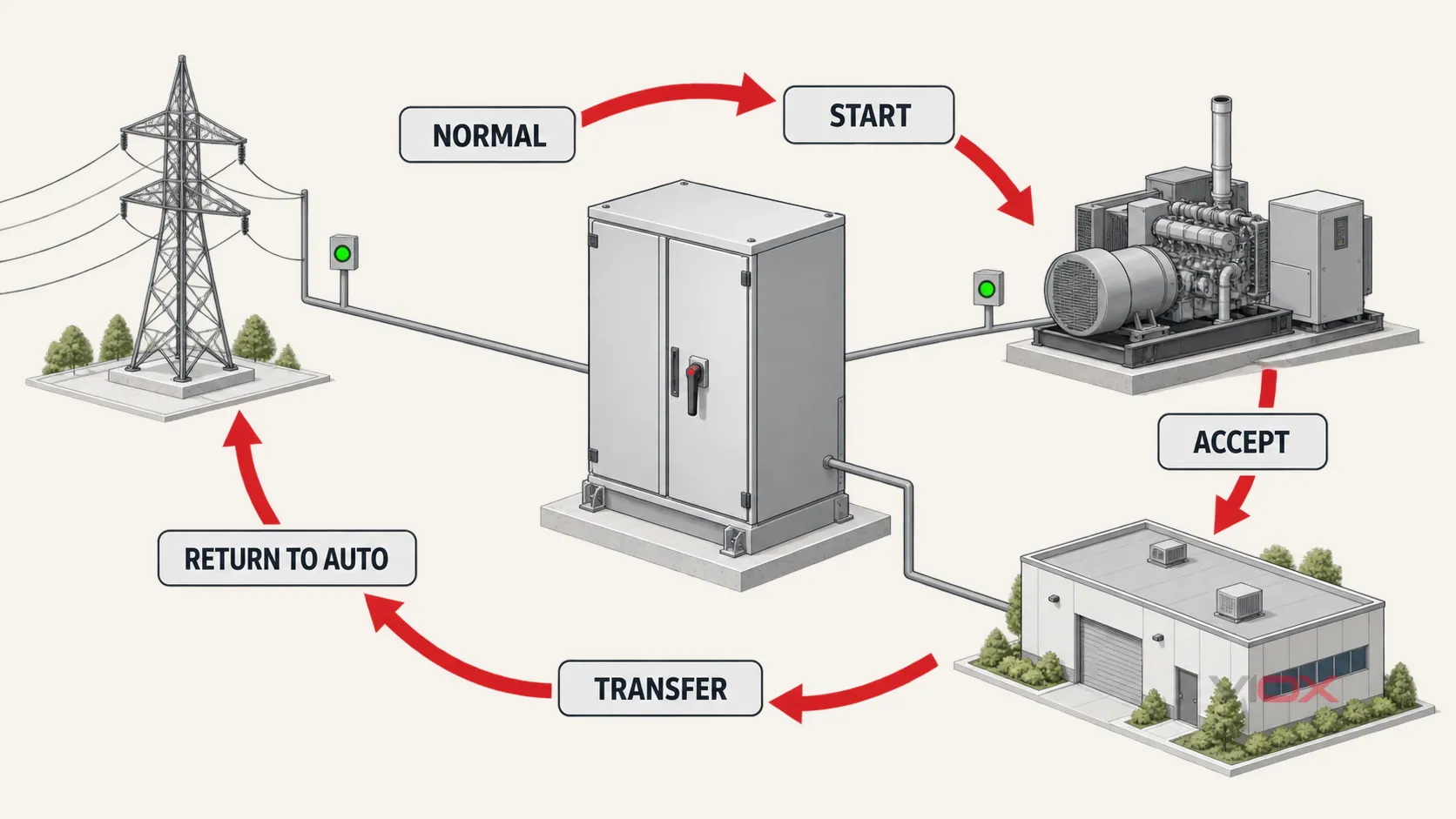
ຫຼັກຖານທີ່ຄາດຫວັງ: ບັນທຶກການທົດສອບທີ່ມີການປະທັບເວລາ ເຊິ່ງປະກອບດ້ວຍວິທີການເລີ່ມຕົ້ນ, ການຕັ້ງຄ່າທີ່ໄດ້ຮັບການອະນຸມັດ, ການປ່ຽນແປງສະຖານະທີ່ສັງເກດເຫັນ, ເງື່ອນໄຂຂອງແຫຼ່ງຈ່າຍທີ່ວັດແທກໄດ້, ຜົນການໂອນຍ້າຍ/ໂອນຍ້າຍຄືນ, ສັນຍານເຕືອນ ແລະ ໂໝດສຸດທ້າຍ.
ເງື່ອນໄຂການຢຸດ: ສະຖານະທີ່ບໍ່ຄາດຄິດ, ຄວາມສ່ຽງໃນການຂະໜານແຫຼ່ງຈ່າຍ, ແຫຼ່ງຈ່າຍທີ່ບໍ່ສະຖຽນ, ການຕິດຂັດທາງກົນຈັກ, ການສະແດງຜົນທີ່ຂັດແຍ່ງກັນ ຫຼື ການບໍ່ສາມາດເຮັດສຳເລັດຂັ້ນຕອນໃດໜຶ່ງ ຈະເປັນການສິ້ນສຸດການທົດສອບປ້ອງກັນ. ໃຫ້ເຮັດໃຫ້ລະບົບຢູ່ໃນສະຖານະທີ່ອະນຸມັດ ແລະ ດຳເນີນການວິນິດໄສຂໍ້ຜິດພາດ. ເຊິ່ງ ຄູ່ມືການແກ້ໄຂບັນຫາ ATS ເປັນຜູ້ຮັບຜິດຊອບຂັ້ນຕອນການເຮັດວຽກຈາກອາການໄປຫາສາເຫດທີ່ຕາມມາ.
5. ກູ້ຄືນ, ກວດສອບ ແລະ ປິດໃບສັ່ງງານ
ການບຳລຸງຮັກສາຍັງບໍ່ທັນສຳເລັດເມື່ອປິດຝາຄອບແລ້ວ. ການກວດສອບຂັ້ນສຸດທ້າຍຕ້ອງພິສູດໃຫ້ເຫັນວ່າການຄວບຄຸມຊົ່ວຄາວ ແລະ ເງື່ອນໄຂການທົດສອບໄດ້ຖືກເອົາອອກແລ້ວ.
ຢືນຢັນ ແລະ ບັນທຶກ:
- ເຄື່ອງມື, ສາຍຈຳເປີ (jumpers), ແຫຼ່ງຈ່າຍຊົ່ວຄາວ, ສາຍທົດສອບ ແລະ ສາຍດິນທັງໝົດໄດ້ຖືກເອົາອອກແລ້ວ;
- ອຸປະກອນປ້ອງກັນ, ແຜງກັ້ນ, ຊ່ອງດັບອາກ (arc chutes), ຝາປິດ ແລະ ປະຕູໄດ້ຖືກຕິດຕັ້ງຄືນຢ່າງຖືກຕ້ອງ;
- ການເຊື່ອມຕໍ່ ແລະ ອົງປະກອບທັງໝົດທີ່ໄດ້ຮັບການບຳລຸງຮັກສາມີບັນທຶກສະພາບຫຼັງການປະຕິບັດງານ;
- ການຕັ້ງຄ່າການປ້ອງກັນ, ການຍອມຮັບແຫຼ່ງຈ່າຍໄຟ ແລະ ການໜ່ວງເວລາ ແມ່ນກົງກັບບັນທຶກທີ່ໄດ້ຮັບການອະນຸມັດ;
- ແຫຼ່ງຈ່າຍໄຟປົກກະຕິ ແລະ ແຫຼ່ງຈ່າຍໄຟສຳຮອງສາມາດໃຊ້ງານໄດ້ຕາມຈຸດປະສົງ;
- ຕຳແໜ່ງຂອງ ATS ແລະ ການສະແດງຜົນໃນທ້ອງຖິ່ນ/ທາງໄກ ມີຄວາມສອດຄ່ອງກັນ;
- ສັນຍານເຕືອນໄພຖືກລຶບລ້າງ ຫຼື ໄດ້ຮັບການຈັດການຢ່າງເປັນທາງການ;
- ຕົວຄວບຄຸມຢູ່ໃນໂໝດ AUTO, ບໍ່ແມ່ນ TEST, MANUAL, OFF ຫຼື BYPASS ເວັ້ນເສຍແຕ່ແຜນການປະຕິບັດງານທີ່ໄດ້ຮັບການອະນຸມັດຈະກຳນົດໄວ້ເປັນຢ່າງອື່ນ;
- ຄວາມສາມາດໃນການເລີ່ມຕົ້ນການເຮັດວຽກອັດຕະໂນມັດຂອງເຄື່ອງກຳເນີດໄຟຟ້າໄດ້ຮັບການຟື້ນຟູ ແລະ ກວດສອບແລ້ວ;
- ບຸກຄະລາກອນປະຕິບັດງານທີ່ກ່ຽວຂ້ອງໄດ້ຍອມຮັບເອົາອຸປະກອນກັບຄືນສູ່ການບໍລິການແລ້ວ;
- ຂໍ້ບົກຜ່ອງ, ການຈັດປະເພດຄວາມສ່ຽງ, ການດຳເນີນການແກ້ໄຂ, ຊິ້ນສ່ວນ ແລະ ວັນທີກວດສອບຄັ້ງຕໍ່ໄປ ຈະຖືກບັນທຶກໄວ້ໃນລະບົບການບຳລຸງຮັກສາ.
ຫຼັກຖານທີ່ຄາດຫວັງ: ບັນທຶກສະພາບຫຼັງການສ້ອມແປງທີ່ໄດ້ລົງນາມແລ້ວ, ການຍອມຮັບການດຳເນີນງານ ແລະ ການອ້າງອີງການດຳເນີນການແກ້ໄຂສຳລັບທຸກຂໍ້ບົກຜ່ອງທີ່ຍັງຄ້າງຄາ.
ການບຳລຸງຮັກສາ ATS ປະເພດ PC-Class ແລະ CB-Class ແມ່ນບໍ່ຄືກັນ
ສະຖາປັດຕະຍະກຳຈະປ່ຽນແປງສິ່ງທີ່ຕ້ອງໄດ້ຮັບການກວດສອບ ແລະ ໜ້າທີ່ການປ້ອງກັນໃດທີ່ຄວນຢູ່ພາຍໃນ ຫຼື ພາຍນອກອຸປະກອນໂອນຍ້າຍໄຟຟ້າ.
- ກ PC-class ATS ນຳໃຊ້ອຸປະກອນສະຫຼັບທີ່ອອກແບບມາເພື່ອໜ້າທີ່ການໂອນຍ້າຍ ແລະ ໂດຍທົ່ວໄປຈະອີງໃສ່ການປ້ອງກັນກະແສເກີນທາງຕົ້ນທາງທີ່ປະສານງານກັນ. ແຜນການບຳລຸງຮັກສາຄວນລະບຸໜ້າສຳຜັດ/ກົນໄກການສະຫຼັບ ແລະ ຄວາມສຳພັນທີ່ແນ່ນອນຂອງອຸປະກອນປ້ອງກັນທາງຕົ້ນທາງ.
- ກ CB-class ATS ລວມເອົາເບຣກເກີວົງຈອນເປັນອຸປະກອນສະຫຼັບ. ດັ່ງນັ້ນ, ກົນໄກຂອງເບຣກເກີ, ໜ້າທີ່ການຕັດ/ຕໍ່ວົງຈອນ ແລະ ການຕັ້ງຄ່າການປ້ອງກັນ ອາດເປັນສ່ວນໜຶ່ງຂອງແຜນການສະເພາະສຳລັບອຸປະກອນນັ້ນໆ.
ຢ່າເພີ່ມການທົດສອບການຣີເຊັດໂຫຼດເກີນ, ໜ່ວຍຕັດວົງຈອນອີເລັກໂທຣນິກ ຫຼື ການທົດສອບການຕັດວົງຈອນຂອງເບຣກເກີເຂົ້າໃນລາຍການກວດສອບ ATS ທຸກຄັ້ງ. ກ່ອນອື່ນໃຫ້ກວດສອບປະເພດອຸປະກອນ ແລະ ແບບແຕ້ມເສຍກ່ອນ. ເອກະສານ ຄູ່ມືການປະສານງານລະຫວ່າງ ATS ແລະ ເບຣກເກີວົງຈອນ ອະທິບາຍເຫດຜົນວ່າເປັນຫຍັງກະແສໄຟຟ້າພິກັດພຽງຢ່າງດຽວ ຈຶ່ງບໍ່ສາມາດກຳນົດຄວາມເໝາະສົມຂອງລະບົບຕໍ່ການຮັບມືກັບກະແສຟອລ໌ດໄດ້.
ຄວນບຳລຸງຮັກສາສະວິດໂອນໄຟຟ້າອັດຕະໂນມັດ (ATS) ເລື້ອຍປານໃດ?
ບໍ່ມີໄລຍະເວລາທີ່ຮັບຜິດຊອບດຽວສຳລັບ ATS ທຸກປະເພດ. ໃຫ້ກຳນົດຄວາມຖີ່ຈາກ:
- ຄຳແນະນຳການບຳລຸງຮັກສາຈາກຜູ້ຜະລິດໂດຍກົງ;
- ສະພາບຂອງອຸປະກອນ ແລະ ແນວໂນ້ມການທົດສອບທີ່ຜ່ານມາ;
- ພາລະການເຮັດວຽກ, ຈຳນວນຄັ້ງໃນການໂອນຍ້າຍ ແລະ ປະຫວັດການເກີດຂໍ້ຜິດພາດ;
- ຝຸ່ນ, ຄວາມຊຸ່ມ, ການປົນເປື້ອນທີ່ກັດກ່ອນ, ການສັ່ນສະເທືອນ, ຄວາມຮ້ອນ ແລະ ສະພາບແວດລ້ອມຂອງຕູ້ຄອນໂທລ;
- ຄວາມສຳຄັນຂອງໂຫຼດທີ່ສະໜອງໄຟໃຫ້ ແລະ ລະບົບສຳຮອງທີ່ມີຢູ່;
- ໂຄງການບຳລຸງຮັກສາລະບົບໄຟຟ້າຂອງສະຖານທີ່;
- ຂໍ້ກຳນົດຂອງລະບົບສຸກເສີນ/ລະບົບສຳຮອງ, ສະບັບຂອງລະຫັດ ຫຼື ມາດຕະຖານທີ່ນຳໃຊ້ ແລະ ໜ່ວຍງານທີ່ມີອຳນາດກຳກັບດູແລ;
- ຂໍ້ກຳນົດຂອງບໍລິສັດປະກັນໄພ, ການຮັບຮອງ ຫຼື ເຈົ້າຂອງໂຄງການ ໃນກໍລະນີທີ່ກ່ຽວຂ້ອງ.
ຄຳແນະນຳກ່ຽວກັບຄວາມຖີ່ໃນການບຳລຸງຮັກສາຂອງ NETA ອະທິບາຍວ່າໂຄງການທີ່ເໝາະສົມຄວນອີງໃສ່ຄວາມໜ້າເຊື່ອຖື ແລະ ມີຄວາມສະເພາະເຈາະຈົງຕໍ່ໂຮງງານ ແລະ ອຸປະກອນນັ້ນໆ. NFPA 70B ສະໜອງໂຄງຮ່າງການບຳລຸງຮັກສາອຸປະກອນໄຟຟ້າທີ່ກວ້າງຂວາງກວ່າ, ແຕ່ສະຖານທີ່ຍັງຕ້ອງກຳນົດວ່າສະບັບໃດ ແລະ ຂໍ້ກຳນົດໃດທີ່ນຳໃຊ້ໄດ້. ລະບົບສຸກເສີນອາດມີພັນທະໃນການກວດສອບການເຮັດວຽກ ຫຼື ການທົດສອບທີ່ຖີ່ກວ່າພາຍໃຕ້ໂຄງການທີ່ກຳກັບດູແລ; ຢ່ານຳໃຊ້ໄລຍະຫ່າງເຫຼົ່ານັ້ນແບບທົ່ວໄປກັບທຸກ ATS ທີ່ເປັນທາງເລືອກສຳຮອງ ຫຼື ທາງອຸດສາຫະກຳ.
ໂຄງການທີ່ໃຊ້ໄດ້ຈິງມັກຈະໃຊ້ຫຼາຍຄວາມຖີ່ພ້ອມກັນ: ການສັງເກດການໂດຍຜູ້ປະຕິບັດງານເລື້ອຍໆ, ການທົດສອບການເຮັດວຽກທີ່ກຳນົດເວລາແຍກຕ່າງຫາກ, ແລະ ການບຳລຸງຮັກສາໃນສະພາບທີ່ຕັດໄຟໂດຍອີງໃສ່ສະພາບການ ຫຼື ຄວາມສ່ຽງ. ດັ່ງນັ້ນ ປະຕິທິນຈຶ່ງເປັນຜົນຜະລິດຂອງຍຸດທະສາດການບຳລຸງຮັກສາ, ບໍ່ແມ່ນຂໍ້ສົມມຸດຕິຖານໃນການເລີ່ມຕົ້ນ.
ສິ່ງທີ່ລາຍງານການບຳລຸງຮັກສາ ATS ທີ່ສົມບູນຄວນມີ
ບົດລາຍງານທີ່ສາມາດກວດສອບໄດ້ຄວນເຮັດໃຫ້ບຸກຄະລາກອນທີ່ມີຄຸນວຸດທິອື່ນເຂົ້າໃຈເຖິງສິ່ງທີ່ພົບເຫັນ, ສິ່ງທີ່ປ່ຽນແປງ ແລະ ເຫດຜົນທີ່ ATS ຖືກນຳກັບມາໃຊ້ງານໃໝ່.
| ກຸ່ມບັນທຶກ | ຊ່ອງຂໍ້ມູນທີ່ຈຳເປັນຂັ້ນຕ່ຳ |
|---|---|
| ຊັບສິນ ແລະ ລະບົບ | ສະຖານທີ່, ແທັກ, ຜູ້ຜະລິດ/ຮຸ່ນ/ເລກລຳດັບ, ຕົວຄວບຄຸມ, ຄ່າພິກັດ, ຈຳນວນຂົ້ວ/ນິວທຣອນ, ຊັ້ນ, ປະເພດການປ່ຽນຜ່ານ, ການຈັດວາງແຫຼ່ງຈ່າຍໄຟ |
| ການຄວບຄຸມວຽກງານ | ໃບສັ່ງງານ, ອ້າງອີງການຕັດໄຟ/ການສະຫຼັບ, ອ້າງອີງ LOTO, ບຸກຄະລາກອນທີ່ມີຄຸນວຸດທິ, ໂຫຼດທີ່ໄດ້ຮັບຜົນກະທົບ, ການອະນຸມັດ ແລະ ວັນທີ |
| ອຸປະກອນທົດສອບ | ID ຂອງເຄື່ອງມື, ໜ້າທີ່, ສະຖານະ/ວັນທີການປັບທຽບ ແລະ ສາຍນຳ/ອຸປະກອນເສີມໃນກໍລະນີທີ່ມີ |
| ສະພາບທີ່ພົບເຫັນ | ຄ່າຈາກແຫຼ່ງຈ່າຍ, ສະພາບໂຫຼດ, ຕຳແໜ່ງ, ໂໝດ, ການຕັ້ງຄ່າ, ສັນຍານເຕືອນ, ບັນທຶກເຫດການ, ຮູບພາບ ແລະ ສະພາບແວດລ້ອມ |
| ການກວດກາ ແລະ ການບໍລິການ | ລາຍການ, ສະຖານທີ່, ຜົນລວມ, ຂໍ້ບົກພ່ອງ, ຄ່າທີ່ອ່ານໄດ້, ເກນທີ່ໄດ້ຮັບການອະນຸມັດ, ການດຳເນີນການ, ຊິ້ນສ່ວນ ແລະ ຜູ້ຮັບຜິດຊອບ |
| ລຳດັບການເຮັດວຽກ | ວິທີການເລີ່ມຕົ້ນ, ແຕ່ລະສະຖານະ/ເວລາ, ແຮງດັນ/ຄວາມຖີ່ໃນກໍລະນີທີ່ຈຳເປັນ, ການສະແດງຜົນ, ການຕອບສະໜອງຂອງໂຫຼດ ແລະ ຜົນລວມ |
| ສະຖານະຫຼັງຈາກການດຳເນີນການ | ຕຳແໜ່ງ, ໂໝດ AUTO, ການຟື້ນຟູການເລີ່ມຕົ້ນອັດຕະໂນມັດ, ການຕັ້ງຄ່າ, ສັນຍານເຕືອນ, ຄວາມພ້ອມຂອງແຫຼ່ງຈ່າຍໄຟ, ການຈັດການຄວາມເປັນລະບຽບຮຽບຮ້ອຍ ແລະ ການຍອມຮັບການປະຕິບັດງານ |
| ການຕິດຕາມຜົນ | ຄວາມຮຸນແຮງຂອງຂໍ້ບົກພ່ອງ, ຂໍ້ຈຳກັດຊົ່ວຄາວ, ເລກທີໃບສັ່ງງານ/ການແກ້ໄຂ, ເຈົ້າຂອງ ແລະ ວັນທີກຳນົດ |
ໃຊ້ ຜ່ານ, ຂໍ້ບົກພ່ອງ ແລະ ບໍ່ມີ ແທນທີ່ຈະເປັນເຄື່ອງໝາຍ “ສຳເລັດ” ທີ່ບໍ່ຊັດເຈນ. ການໝາຍຕິກໃນຊ່ອງທີ່ກຳນົດໄວ້ເປັນການພິສູດວ່າໄດ້ມີການບັນທຶກການດຳເນີນການໄວ້ແລ້ວ; ມັນບໍ່ໄດ້ເປັນການພິສູດວ່າອຸປະກອນດັ່ງກ່າວໄດ້ຜ່ານເກນການຍອມຮັບ.
ຕັດສິນໃຈຜົນການບຳລຸງຮັກສາ
ປິດການເຂົ້າກວດສອບດ້ວຍໜຶ່ງໃນສາມຜົນລັດທີ່ຊັດເຈນດັ່ງນີ້:
- ກັບຄືນສູ່ການໃຊ້ງານ: ການກວດສອບທີ່ຈຳເປັນທັງໝົດໄດ້ສຳເລັດແລ້ວ, ຜົນການກວດສອບໄດ້ຕາມມາດຖານທີ່ລະບຸໄວ້, ການຕັ້ງຄ່າການປ້ອງກັນ ແລະ ການຄວບຄຸມແມ່ນຖືກຕ້ອງ, ແລະ ATS ໄດ້ຮັບການຢັ້ງຢືນໃນສະຖານະອັດຕະໂນມັດທີ່ໄດ້ຮັບການອະນຸມັດແລ້ວ.
- ກັບຄືນສູ່ການໃຊ້ງານພ້ອມຂໍ້ຈຳກັດທີ່ໄດ້ບັນທຶກໄວ້: ເຈົ້າໜ້າທີ່ຜູ້ຮັບຜິດຊອບຍອມຮັບເງື່ອນໄຂຊົ່ວຄາວທີ່ກຳນົດໄວ້, ມາດຕະການຊົດເຊີຍ, ເຈົ້າຂອງ ແລະ ກຳນົດເວລາໃນການແກ້ໄຂ. ລາຍການກວດສອບພຽງຢ່າງດຽວບໍ່ສາມາດອະນຸມັດການຕັດສິນໃຈນີ້ໄດ້.
- ຫ້າມກັບຄືນສູ່ການບໍລິການແບບອັດຕະໂນມັດ: ຂໍ້ບົກຜ່ອງທີ່ສຳຄັນດ້ານຄວາມປອດໄພ, ການແຍກວົງຈອນທີ່ບໍ່ແນ່ນອນ, ລຳດັບການໂອນຍ້າຍທີ່ລົ້ມເຫຼວ, ກົນໄກທີ່ເສຍຫາຍ, ຜົນທາງໄຟຟ້າທີ່ບໍ່ຍອມຮັບໄດ້ ຫຼື ບັນຫາການຄວບຄຸມທີ່ຍັງບໍ່ໄດ້ຮັບການແກ້ໄຂ ເຮັດໃຫ້ບໍ່ສາມາດຟື້ນຟູການໃຊ້ງານຢ່າງປອດໄພໄດ້.
ການເປີດ-ປິດ ATS ທີ່ເສຍຫາຍຊ້ຳໆ ບໍ່ແມ່ນການບຳລຸງຮັກສາແບບປ້ອງກັນ. ໃຫ້ຮັກສາລະບົບໃຫ້ປອດໄພພາຍໃຕ້ແຜນການປະຕິບັດງານທີ່ໄດ້ຮັບການອະນຸມັດ, ເກັບຮັກສາຫຼັກຖານ ແລະ ເລີ່ມຕົ້ນຂະບວນການແກ້ໄຂບັນຫາ ຫຼື ການສ້ອມແປງທີ່ມີການຄວບຄຸມ.
ດາວໂຫຼດລາຍການກວດສອບການບຳລຸງຮັກສາປ້ອງກັນ ATS
ໃຊ້ເອກະສານວຽກ VIOX ທີ່ສາມາດດາວໂຫຼດໄດ້ ເພື່ອບັນທຶກຂໍ້ມູນໂຄງການ, ລາຍການກວດສອບ, ການທົດສອບການເຮັດວຽກ, ຜົນການທົດສອບພິເສດໃນກໍລະນີທີ່ໄດ້ຮັບອະນຸຍາດ, ການທົບທວນຄັ້ງສຸດທ້າຍ ແລະ ການລົງນາມອະນຸມັດ:
ດາວໂຫຼດລາຍການກວດສອບການບຳລຸງຮັກສາແບບປ້ອງກັນ ATS ຂອງ VIOX Electric (PDF)
PDF ນີ້ແມ່ນແມ່ແບບເອກະສານ. ມັນບໍ່ໄດ້ໃຊ້ແທນຄຳແນະນຳທີ່ແນ່ນອນຈາກຜູ້ຜະລິດ ATS, ວິທີການສະຫຼັບແລະການທົດສອບທີ່ໄດ້ຮັບການອະນຸມັດ, ຂໍ້ກຳນົດຂອງເຄື່ອງມືທີ່ໄດ້ຮັບການປັບທຽບ, ໂຄງການຄວາມປອດໄພທາງໄຟຟ້າຂອງສະຖານທີ່ ຫຼື ກົດລະບຽບທ້ອງຖິ່ນທີ່ກ່ຽວຂ້ອງ. ໃຫ້ໝາຍລາຍການທີ່ບໍ່ກ່ຽວຂ້ອງໃຫ້ຊັດເຈນ, ແລະ ຫ້າມດຳເນີນການທົດສອບຄວາມຕ້ານທານຂອງສນວນ (insulation-resistance) ຫຼື ການທົດສອບຄວາມທົນທານຕໍ່ໄຟຟ້າ (dielectric-withstand) ເວັ້ນເສຍແຕ່ວ່າໄດ້ມີການກຳນົດການຕັ້ງຄ່າການທົດສອບສະເພາະຂອງອຸປະກອນ ແລະ ໄດ້ຮັບການອະນຸຍາດແລ້ວ.
ແຫຼ່ງຂໍ້ມູນທາງເຕັກນິກ
- IEC 60947-6-1:2026 — ອຸປະກອນສະວິດໂອນຍ້າຍ
- NFPA 70B — ມາດຕະຖານສຳລັບການບຳລຸງຮັກສາອຸປະກອນໄຟຟ້າ
- ANSI/NETA MTS-2023 — ຂໍ້ກຳນົດສະເພາະດ້ານການທົດສອບການບຳລຸງຮັກສາ
- NETA — ຄວາມຖີ່ໃນການບຳລຸງຮັກສາ
- OSHA — ການຄວບຄຸມພະລັງງານອັນຕະລາຍສຳລັບການຜະລິດພະລັງງານໄຟຟ້າ
- OSHA — ການປ່ອຍກະແສໄຟຟ້າຊົ່ວຄາວເພື່ອການທົດສອບ ຫຼື ການຈັດຕຳແໜ່ງ