
電気エンジニアが図面に「IEC 61008-1 準拠の RCCB が必要」と記載した場合、その一文が、定格電圧、感度閾値、短絡保護協調、試験プロトコルなど、一連の技術的な決定事項を引き起こします。認証機関に機器を提出する製造業者にとって、IEC 61008-1 は、数ヶ月にわたる設計検証と数百回もの試験サイクルを意味します。サプライヤーの主張を評価する調達担当者にとって、それは本物の認証とマーケティングの宣伝文句との違いです。.
IEC 61008-1 は、以下を規定する国際規格です。 漏電遮断器(RCCB) 一体型過電流保護なし。国際電気標準会議によって最初に発行されたこの規格は、RCCB が確実に地絡電流を検出し、感電を防止するための技術要件、試験手順、および性能基準を定義しています。2024 年にリリースされた第 4 版では、一時的な過電圧耐性試験や、IEC 61008/61009/60755 ファミリー全体での要件の調和など、重要な更新が導入されました。.
このガイドでは、IEC 61008-1 を抽象的な規格の文言から、実行可能なエンジニアリングの知識に翻訳します。適用範囲の境界を説明し、定格量の表を解読し、主要な試験要件をそれぞれ説明し、2024 年版での変更点を明確にします。認証ドキュメントの準備、プロジェクト用の RCCB の仕様決定、またはサプライヤーの試験レポートの検証のいずれを行う場合でも、IEC 61008-1 が実際に要求していること、およびそれらの要件が現場での性能にとってなぜ重要なのかについて、明確なロードマップを得ることができます。.
IEC 61008-1 の概要と適用範囲
IEC 61008-1 は、世界中の RCCB の安全性の基礎を確立しますが、その適用範囲には正確な境界があります。規格が対象とするものと、意図的に除外するものを理解することで、仕様の誤りや認証の際の驚きを防ぐことができます。.
IEC 61008-1 の対象範囲
この規格は、漏電遮断器に適用されます。 一体型過電流保護なし。. この区別は重要です。IEC 61008-1 は、差動電流検知によって地絡電流を検出するスタンドアロンの RCCB を規定していますが、短絡および過負荷保護については、上流の回路ブレーカー(MCB または MCCB)に依存しています。両方の機能を組み合わせたデバイス(RCBO(過電流保護機能付き漏電遮断器))は、別の IEC 61009 規格の対象となります。.
この適用範囲は、主に家庭、商業、および同様の設備における感電からの保護を目的とした RCCB を対象としています。これらのデバイスは、相導体と中性導体間の電流の不均衡を検知することによって動作します。漏洩電流が定格残留動作電流(IΔn)を超えると(通常、地絡または絶縁破壊が原因)、RCCB はミリ秒以内にトリップし、危険なショックレベルが発生する前に回路を切断します。.
技術的な境界と制限
IEC 61008-1 は、明確な動作制限を設定しています。
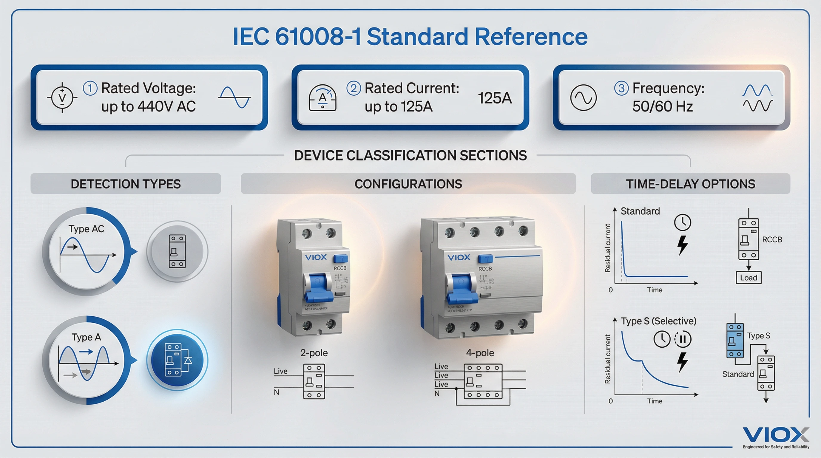
- 定格使用電圧(Un): 最大 440 V AC
- 定格電流(In): 最大 125 A
- 定格周波数: 50 Hz または 60 Hz
デバイスは、一貫した残留電流感度を維持しながら、これらの範囲全体で動作する必要があります。この規格は、機能的に独立した RCCB(外部電源を必要としない機械式トリップ機構)と、線間電圧に依存する設計(動作に電源電圧を必要とする電子式 RCCB)の両方に対応しています。各分類は、特に電圧低下または中断時の動作について、異なる試験要件を引き起こします。.
IEC 61008-1 に基づくデバイスの分類
この規格は、いくつかの側面から RCCB を分類しています。
タイプ AC とタイプ A の検出: IEC 61008-1 は、2 つの基本的な検出タイプを対象としています。タイプ AC RCCB は、正弦波 AC 残留電流(抵抗負荷からの従来の地絡の兆候)に応答します。タイプ A デバイスは、脈動 DC 残留電流(最新の電子機器、LED ドライバー、および可変速アプライアンスで一般的な半波整流波形)に対する感度を追加します。両方のタイプは、規格の試験条項に詳述されている特定の時間-電流動作曲線を満たす必要があります。.
時間遅延特性: 標準(瞬時)RCCB は、意図的な遅延なしにトリップします。タイプ S(選択的)RCCB は、時間遅延を組み込んでおり、下流のデバイスが最初に障害を除去できるようにします。これは、配電システムにおける協調保護に不可欠です。第 4 条は分類の枠組みを定義し、第 9 条は対応する試験手順を規定しています。.
極構成: この規格は、2 極(単相)および 4 極(三相)構成を対象としており、配線および試験要件は各トポロジに合わせて調整されています。.
2024 年版への移行
2024 年 11 月 21 日に、IEC は統合された第 3 版(IEC 61008-1:2010+A1:2012+A2:2013)を正式に廃止し、第 4 版を発行しました。この移行は、10 年以上で最も重要な更新となります。主な変更点は次のとおりです。
- 規格間の調和: 2024 年版では、IEC 61009(RCBO)および IEC 60755(一般的な RCD 要件)と共有されるモジュール式の「ブロックとモジュール」構造を採用しています。この調整により、矛盾が減少し、複数の規格への準拠が簡素化されます。.
- 新しい TOV 要件: サブ条項 8.17 および 9.24 では、一時的な過電圧(TOV)耐性に関する必須試験が導入されています。再生可能エネルギーの統合とグリッドの不安定性が増大するにつれて、RCCB は現在、過去の基準を超える過渡電圧ストレスに直面しています。TOV 試験では、デバイスが劣化や誤トリップなしに電圧スパイクに耐えることを検証します。.
- 改善された絶縁耐力試験: 強化された手順は、特に敏感な制御回路を備えた電子式 RCCB について、実際の絶縁ストレスをより適切に反映しています。.
- 端子と導体の参照: この規格は、端子の設計と試験について IEC 62873-3 シリーズを参照するようになり、より広範な低電圧開閉装置の実践との一貫性を確保しています。.
2010+AMD 版で認証された製造業者は、移行期間に直面しています。既存の認証は引き続き有効ですが、新しい提出および再認証には、2024 年の要件に合わせた試験が必要です。調達チームにとって、これはサプライヤーの認証がどの版を参照しているかを確認することを意味します。特に、リードタイムが長いプロジェクトや複数年の供給契約の場合に重要です。.
IEC 61008-1 の対象外
境界を理解することも同様に重要です。
- タイプ F およびタイプ B RCCB: 周波数応答の向上(EV 充電で一般的なタイプ F)または完全な DC 残留電流検出(太陽光インバーターおよび VFD に必要なタイプ B)のために設計されたデバイスは、 IEC 62423. の追加要件を満たす必要があります。その規格は IEC 61008-1 を補完するものであり、タイプ F/B 認証では両方が同時に適用されます。.
- RCBO(過電流 + 漏電保護の組み合わせ): IEC 61009 によって規定されており、多くの IEC 61008-1 条項を参照していますが、過電流保護協調要件が追加されています。.
- アプリケーション固有の設置: IEC 61008-1 は製品要件を定義しています。設置方法、回路設計規則、および必須の RCCB の場所は、地域の電気工事規定(北米の NEC 第 210.8 条、英国の BS 7671、ドイツの DIN VDE)で規定されています。.
主要な技術要件
IEC 61008-1 は、定格量(製造業者が宣言し、試験で検証する値)を通じて技術要件を定義しています。これらのパラメーターは、感度閾値から短絡耐量まで、すべてを規定します。.
定格量とパラメーター
すべての RCCB の銘板には、一連の定格値が記載されています。それぞれの意味と、それが重要な理由を以下に示します。
定格電圧(Un): RCCB が継続的に処理するように設計されている最大動作電圧。一般的な値には、230V(単相住宅)、400V/415V(三相産業)などがあります。デバイスは、通常 Un の 85% から 110% までの電圧範囲全体で、指定された性能を維持する必要があります。.
定格電流(In): RCCB が温度上昇制限を超えずに運ぶことができる最大連続負荷電流。標準値には、16A、25A、32A、40A、63A、80A、100A、および 125A があります。これはトリップ電流ではありません。通常の動作のための熱容量です。RCCB は、第 9.12 条に規定されている制限内で接点温度の上昇を維持しながら、In を継続的に通過させる必要があります。.
定格残留動作電流(IΔn): RCCB をトリップさせる差動電流。これは、中核となる安全パラメーターです。標準的な感度には、以下が含まれます。
-sensitivity-levels-and-their-applications.webp)
- 10 mA: 特殊な用途(医療機器、スイミングプール)向けの高感度保護
- 30 mA: 感電防止のための個人保護規格(ほとんどの規定でソケット回路に必須)
- 100 mA: 商業/産業施設における火災保護
- 300 mA および 500 mA: 配電系統における選択遮断協調、機器保護
正確にIΔnにおいて、RCCBは指定された時間制限内に確実にトリップしなければなりません。IEC 61008-1はまた、IΔno(定格残留非動作電流)を定義しています。これは、デバイスがトリップしてはならない最大リーク電流です。ほとんどのRCCBでは、IΔno = 0.5 × IΔnです。このバッファは、通常のバックグラウンドリークによる不要なトリップを防ぎます。.
定格投入遮断容量 (Im): RCCBが短絡条件下で安全に投入または遮断できる最大予想電流。代表的な値:500A、1000A、1500A、3000A、6000A、10000A。これは定格短絡電流(上流のSCPD保護が必要)ではなく、RCCBが溶接や爆発なしに故障条件下で接点を動作させる能力です。.
定格残留投入遮断容量 (IΔm): Imと同様ですが、残留故障電流に対するものです。RCCBは、故障電流が短絡レベルに近づいても、地絡をトリップして除去する必要があります。標準値:住宅用デバイスでは500A、1000A、1500A。産業用アプリケーションではより高い値。.
定格条件付き短絡電流 (Inc) および定格条件付き残留短絡電流 (IΔc): これらは、指定された短絡保護デバイス(SCPD)(通常は上流のMCBまたはヒューズ)によって保護されている場合に、RCCBが耐えることができる最大故障電流を定義します。協調により、SCPDはRCCBが損傷を受ける前に高故障電流を除去します。条項9.14は、Inc/IΔcまでの予想電流を印加し、その後RCCBが機能し続けることを検証する短絡協調テストについて詳述しています。 MCB またはヒューズ。協調により、SCPDはRCCBが損傷を受ける前に高故障電流を除去します。条項9.14は、Inc/IΔcまでの予想電流を印加し、その後RCCBが機能し続けることを検証する短絡協調テストについて詳述しています。.
動作特性と時間電流曲線
IEC 61008-1は、IΔnのさまざまな倍数でのトリップに対する正確な時間制限を指定しています。これらの動作特性により、メーカー間で一貫したパフォーマンスが保証されます。
タイプACおよびタイプA RCCB(正弦波AC残留電流)の場合:
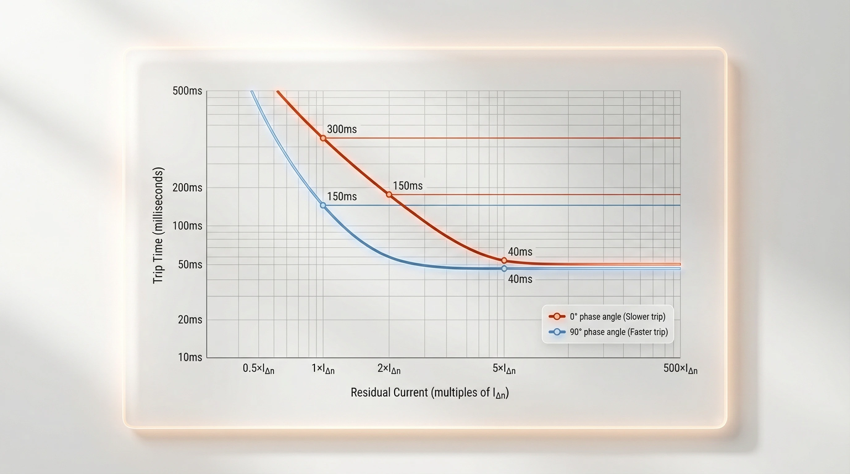
- で IΔn (定格の1倍): 0°の位相角で300 ms以内、90°の位相角で150 ms以内にトリップする必要があります。
- で 2 × IΔn: 0°で最大150 ms、90°で40 ms
- で 5 × IΔn: 0°および90°で最大40 ms
- で 500 × IΔn (高電流テスト): 最大40 ms
位相角の依存性は、トロイダルコアの動作を反映しています。ゼロクロス(0°)で開始する残留電流は、ピーク(90°)で開始する電流よりも遅い磁束の蓄積を生成します。規格は、最悪のシナリオを考慮しています。.
脈動DC残留電流を伴うタイプA RCCBの場合: 半波整流電流(電子負荷の故障をシミュレート)がデバイスをトリガーする場合、追加の制限が適用されます。脈動DCのIΔnでは、最大トリップ時間は300 ms(0°)および200 ms(90°)です。これらのより長いウィンドウは、脈動DCが半サイクル中にのみトロイダルコアにエネルギーを供給するという事実に対応しています。.
タイプS(選択遮断)RCCB: これらは、協調のために意図的な遅延を組み込んでいます。最小非動作時間は、2 × IΔnで130 msから500 msの範囲であり、下流の瞬時RCCBが最初に故障を除去できるようにします。5 × IΔn以上では、タイプSデバイスは安全を確保するために150 ms以内にトリップする必要があります。.
非作動電流制限: 0.5 × IΔn(IΔnoしきい値)では、RCCBは最も不利な位置で2時間安定している必要があります。この安定性テストは、上限および下限温度制限で実施され、デバイスが通常の回路リークまたは高調波電流による不要なトリップに抵抗することを保証します。.
分類と特別な要件
サージ耐性分類: 2010+AMDおよび2024エディションでは、サージ耐性テストが義務付けられています。RCCBは2つのサージプロファイルに直面しています。
- 0.5 μs / 100 kHzリング波: スイッチング操作からの高速トランジェントをシミュレートします。RCCBは、トリップや損傷なしにこれに耐える必要があります。.
- 8/20 μsサージ電流: 最大3000Aピークまでの標準インパルス波形。テストでは、雷によるサージまたはコンデンサ突入中にデバイスが誤ってトリップしないことを検証します。.
DC成分耐性(タイプA要件): タイプA RCCBは、最大6 mAの滑らかなDC電流がトロイダルコアを流れても、残留電流を検出する必要があります。滑らかなDCは一定の磁束バイアスを作成し、コアを飽和させ、AC地絡に対してデバイスを「盲目」にする可能性があります。条項9.9.4は、通常の動作特性テスト中に6 mA DCを重ね合わせることによってこれをテストします。RCCBは制限内でトリップする必要があります。この要件は、整流された負荷(洗濯機、VFD)がDCをリークし、感電保護を無効にする危険なシナリオを防ぎます。.
テスト要件
IEC 61008-1の条項9には、すべてのRCCB設計が認証前に合格する必要がある型式試験の中心が含まれています。これらのテストは、定格量がストレス(熱、湿度、機械的衝撃、電気的トランジェント、および短絡力)下で実際のパフォーマンスに変換されることを検証します。.
型式試験の概要
型式試験は破壊的で包括的であり、大量生産前に代表的なサンプルで実施されます。規格は、さまざまな故障モードを調査するファミリでテストを構成します。
- マーキングと構造: マーキングが永続的であり、端子が指定された導体サイズを受け入れ、機械的アセンブリが寸法公差を満たしていることの検証。.
- 感電からの保護: ライブ部品にアクセスできないことを保証するための標準テストフィンガーによる寸法チェック。.
- 誘電特性: 湿度プレコンディショニング、絶縁抵抗テスト、および高電圧インパルス耐性テスト(最大8kV)を通じて絶縁システムにストレスを与えます。.
- 温度上昇試験: 連続定格電流下で、接点温度上昇が制限内(通常は最大50K)に留まることを検証します。.
- 動作特性: 機能テストの中心であり、さまざまな残留電流レベル、位相角、および環境極端でのトリップ時間を検証します。.
- 短絡動作: SCPDと連携して、RCCBはIncまでの予想電流に直面します。接点を溶接したり、分解したりしてはなりません。.
- 耐久性: 長年のフィールド操作をシミュレートするための4,000回の機械的サイクルと2,000回の電気的サイクル。.
特殊なテスト(新規および強化された要件)
サージ耐性テスト: 2つの補完的なテストは、さまざまな過渡現象の脅威に対処します。スイッチングトランジェント用の0.5 μs / 100 kHzリング波、および雷によるサージ用の8/20 μsサージ電流(最大3000A)。.
タイプAのDC成分テスト: タイプA RCCBは、6 mAの滑らかなDCがコアを飽和させている間でも、AC故障でトリップできることを示す必要があります。.
一時的過電圧(TOV)耐性 – 2024年版の新機能: 2024年版の最も重要な追加機能。RCCBは、グリッドの擾乱をシミュレートした持続的な過電圧試験に耐える必要があります。RCCBは、トリップまたは故障することなく、指定された時間、1.5 × Unに耐えなければなりません。これは、再生可能エネルギーの統合で観察された現場での故障に対処するものです。.
コンプライアンスと認証
個々のテストに合格することは必要ですが、十分ではありません。IEC 61008-1は、テストシーケンス、サンプル数、および継続的な検証を定義する附属書を通じて、コンプライアンスを構成します。.
附属書A:テストシーケンスとサンプル数
附属書Aは、型式試験プログラムを調整します。一般的な認証では、製品範囲に応じて12〜20個のRCCBサンプルが必要です。サンプルは、徹底的な検証を確実にするために、シーケンス(例:非破壊、絶縁耐力、短絡、耐久性)に分割されます。.
附属書D:製造における日常試験
型式試験は設計を検証します。日常試験は、製造されたすべてのユニットを検証します。必須の日常試験には、絶縁耐力、動作特性の検証、およびトリップフリー機構のテストが含まれます。.
結論
IEC 61008-1は、感電防止を安全原則から工学的な現実へと変換します。この規格の定格量は境界を定義し、その時間-電流曲線は一貫した感度を保証し、そのテストプロトコルはストレス下での性能を検証します。製造業者にとって、それは信頼性の高い設計の青写真です。仕様作成者にとって、それはアプリケーション要件と製品機能を橋渡しする共通言語です。調達チームにとって、それはマーケティングの主張から真のコンプライアンスを分離する検証フレームワークです。.
2024年版は、進化する電気環境(再生可能エネルギーの過渡現象、電子負荷の普及、グリッドの不安定性)を反映しています。一時的な過電圧試験、調和された構造、および強化された絶縁耐力検証により、RCCBは最新の設備に遅れを取らないようにします。太陽光インバーター、EV充電器、および可変周波数ドライブが例外ではなく標準になるにつれて、IEC 61008-1:2024は、理想的な実験室環境だけでなく、実際に構築している複雑で過渡現象に満ちたシステムでも機能する保護の基盤を提供します。.
VIOX Electricでは、IEC 61008-1への準拠はチェックボックスではなく、出発点です。当社のVKL11、VML01B、およびVKL11Fシリーズは、独立した認証によって検証されたマージンで2024年版の要件を満たしています。当社は、原材料から製造テストまで完全なトレーサビリティを維持しており、20年以上の製造経験と、標準への不適合に起因する現場での故障はゼロです。.
プロジェクト用にIEC 61008-1に準拠したRCCBを指定する準備はできましたか?
連絡先 技術的な相談、テストレポート、および製品選択のガイダンスについては、当社のエンジニアリングチームにお問い合わせください。.
