
現代の電気システムにおいて、短絡故障はミリ秒単位で壊滅的なエネルギーを放出する可能性があります。50,000アンペアの予想故障電流は、母線を曲げるのに十分な強力な磁気力、銅導体を蒸発させるのに十分な強烈な熱エネルギー、および作業員を危険にさらすアークフラッシュ災害を発生させます。しかし、この破壊の大部分は防止可能です。.
限流遮断器は、回路保護技術における根本的な進歩を表しています。交流波形の自然なゼロクロッシングで故障を遮断する従来の遮断器とは異なり、限流遮断器はミリ秒単位で動作し、故障電流が破壊的なピークに達する前にこれを抑制します。この迅速な介入により、電気設備への機械的・熱的ストレスが大幅に軽減され、精密電子機器の損傷から保護され、アークフラッシュ災害が著しく緩和されます。.
配電システムを設計する電気技術者、保護装置を選定するパネルメーカー、重要インフラを担当する施設管理者にとって、限流技術を理解することは不可欠です。本ガイドでは、限流遮断器の動作原理、性能を定義する主要な仕様、およびこの技術が標準的な回路保護よりも決定的な利点を発揮する状況について説明します。.
限流遮断器とは何ですか?
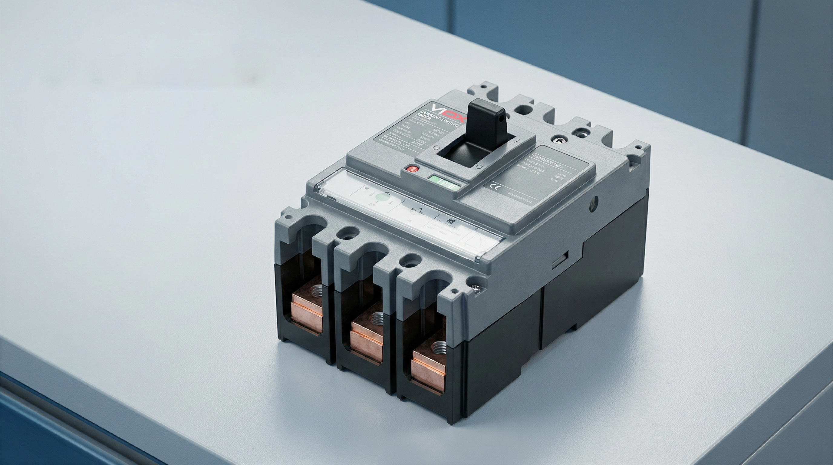
限流遮断器は、短絡電流が最大予想ピーク値に達する前に遮断するように設計された保護装置です。この能力により、通常は故障電流が自然な零点で遮断される前に完全なピーク値に達するまで許容する従来の遮断器と区別されます。.
電気システムで短絡が発生すると、電流は非常に高い速度で上昇を開始し、ミリ秒単位で数万アンペアに達する可能性があります。標準的な遮断器はこの故障状態を検知し、トリップ機構を作動させますが、遮断プロセスには時間がかかります。この短い間隔の間に、故障電流は完全な予想ピークに達し、導体、母線、下流設備に負荷をかける膨大なエネルギーを放出する可能性があります。.
一方、限流遮断器は並外れた速さで動作します。UL 489(北米の配線用遮断器規格)によれば、遮断器が故障を半サイクル未満(通常10ミリ秒未満)で遮断する場合、「限流」とみなされます。この高速応答により、系統電圧に対抗する高いアーク電圧が発生し、電流の流れを効果的に抑制し、通過ピーク電流を予想故障電流よりもはるかに低い値に強制的に低下させます。.
その結果は劇的です:予想故障電流が実効値50,000アンペア(対称)であっても、限流遮断器は実際のピーク電流を15,000アンペア以下に制限する可能性があります。このピーク電流と総故障エネルギーの低減により、下流設備は、そうでなければ発生する機械的力、熱損傷、アークフラッシュの危険から保護されます。.
限流遮断器の動作原理
これらの遮断器の限流能力は、機械設計、電磁気学、アーク管理を慎重に設計して組み合わせた結果です。このプロセスは、いくつかの連携したメカニズムを通じて、ミリ秒単位で展開します。.
電磁力による接点分離
最初の重要な要素は、超高速の接点分離です。高い故障電流が遮断器の接点を流れると、この電流によって生成される巨大な磁場が強力な電磁力を生み出します。限流遮断器は、これらの力を利用して分離を補助する接点構成で設計されています。つまり、磁場が反発力を生み出して文字通り接点を吹き飛ばすように配置されています。.
この「電磁反発」は、より高い故障電流が実際に接点分離を加速することを意味します。遮断器はトリップ機構の機械力だけに依存せず、故障電流自体が接点をより速く開くためのエネルギーを供給します。これにより、故障発生から1~2ミリ秒以内という極めて迅速な接点分離が保証されます。.
アークの発生と伸長
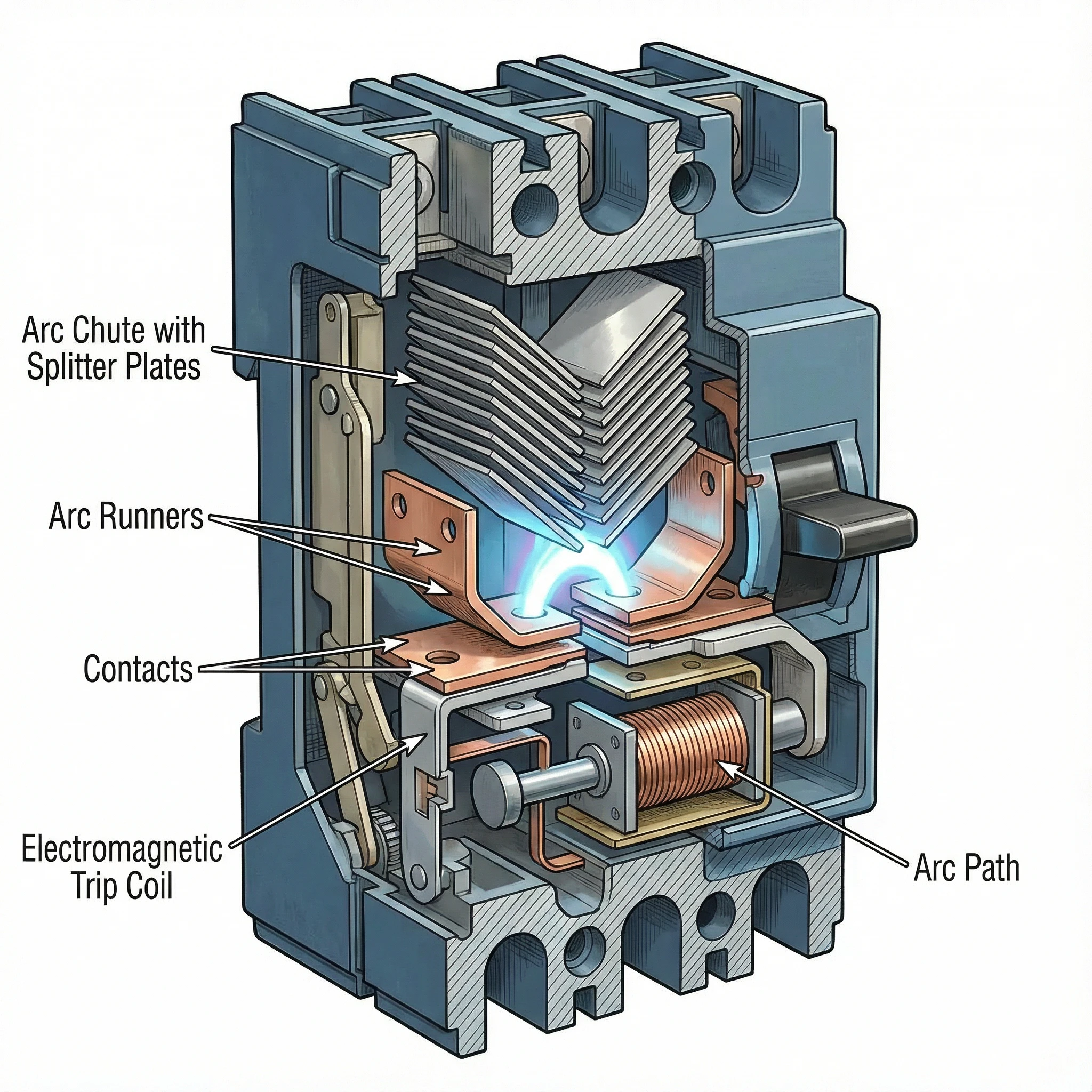
接点が高速で分離すると、隙間に電気アークが形成されます。このアークは抑制すべき問題というよりも、電流制限の主要な手段となります。遮断器の内部構造は、このアークを接点から急速に遠ざけ、アークシュートと呼ばれる特別に設計された消弧室に導き入れるように設計されています。.
電流の流れによって生成される磁場とアークランナーの物理的形状が、アークを上方のアークシュートへと導きます。アークが移動・伸長するにつれて、その長さは劇的に増加します。より長いアークを維持するにはより高い電圧が必要であり、このアーク電圧が故障電流を駆動する系統電圧に対抗します。.
アークの整流と分割
アークシュートには、特定の構成(多くの場合V字型)で配置された一連の金属板(アークスプリッターまたはアークディバイダー)が含まれています。アークがシュート内に導かれると、これらの板に接触し、「整流」されます。つまり、主アーク経路からスプリッタープレートへと移行します。.
このプロセスにより、単一の高エネルギーアークが直列接続された複数の小さなアークに効果的に分割されます。各小さなアークは独自の電圧降下を発生させます。例えば、アークシュートに20枚のスプリッタープレートが含まれている場合、総アーク電圧は系統電圧の何倍にも達する可能性があります。累積アーク電圧が系統電圧を超えると、電流は急速に減少することを余儀なくされます。.
アークの冷却と消弧
金属製スプリッタープレートは、ヒートシンクとしても機能し、アークを急速に冷却します。プレートはアークの表面積を増やし、熱を逃がします。周囲の空気や消弧ガスと組み合わさることで、この冷却によりアークの導電性が低下します。.
高いアーク電圧(電流の流れに対抗)とアーク冷却(導電性の低下)の相互作用により、電流はゼロに向かって強制されます。遮断器は、故障電流がその予想ピークに達する前に、サイクルの一部の時間内でアークを消弧し、故障を遮断します。.
このシーケンスは、障害検出から接触分離、アーク伸長、分裂、絶滅まで、10ミリ秒以下で実行されます。電流は自然なゼロ交差で遮断されるのではなく、アークが持続できない条件を作り出すことによって強制的に遮断されます。.
主な技術仕様
電流制限性能を理解するには、ブレーカが障害電流を効果的に制限し、下流装置を保護する方法を定義する3つの重要な仕様に精通している必要があります。.
現在Let-Through (Ip)
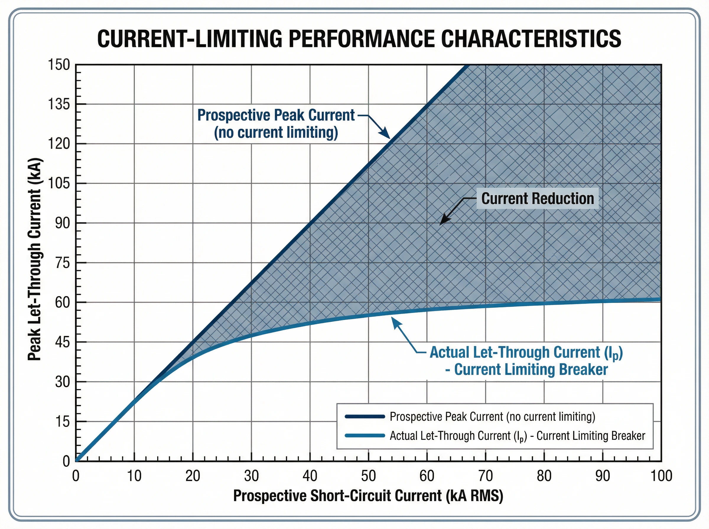
について 現在let-through (Ip) 障害時にブレーカを流れる実際のピーク電流で、単位はアンペアです。この値は、ブレーカの電流制限の有効性を表します。ipが低いほど電流制限が優れていることを示します。.
メーカーは、特性曲線の形でレットスルー電流データを提供しています。このグラフは、縦軸にピークスルー電流(ip)を、横軸に見込み短絡電流(rms対称アンペア)をプロットしたものです。設置点における任意の将来の断層レベルに対して、曲線は実際に流れる最大ピーク電流を示します。.
たとえば、パネルボードで利用可能な障害電流が42,000アンペアrms対称である場合、電流制限ブレーカによって実際のピーク電流がわずか18,000アンペアに制限される可能性があります。このプロポーティブ電流から実際のピーク電流への低減は、バスバーを曲げから保護し、導体の過熱を防止し、すべての下流コンポーネントの機械的応力を低減します。.
応力(I²t)
について I²t値 アンペア2乗秒(a²s)単位で測定される「i-square -t」は、故障除去中にブレーカが通過する熱エネルギーを定量化する。これは、合計クリア時間の現在の二乗の積分を表します。.
この仕様は、ケーブルおよび敏感な電子機器を保護するために重要です。ケーブルの絶縁は、i²tと表される特定の耐熱定格を有する。保護装置がケーブルが耐えられる以上の熱エネルギーを通すと、ケーブルが物理的に溶けていなくても絶縁体は損傷します。.
電流制限ブレーカは標準ブレーカに比べてi²tを大幅に削減する。同じ将来障害電流の場合、電流制限デバイスは、従来のブレーカよりも50-801 tp3t低いi²tの値を持つ可能性があります。これにより、熱応力が低減され、導体の損傷を防ぎ、ケーブル絶縁を保護し、機器の寿命を延長します。.
製造メーカーは、将来の故障電流の関数として最大熱エネルギーを示す、レットスルー電流曲線と同様のi²t曲線を提供している。いくつかの規格では、i²tの性能に基づいて遮断器のエネルギー制限クラスを定義している。.
ブレイキング・キャパシティー(icuとics)
について 遮断容量 ブレーカが安全に遮断できる最大障害電流を定義します。iec 60947-2(低電圧サーキットブレーカの国際規格)には、次の2つの定格が該当します。
- 最終破断容量(Icu)ブレーカが破壊されることなく中断できる最大障害電流。icuレベルで障害を中断した後、ブレーカは継続的なサービスに適しておらず、交換が必要な場合があります。これは、ブレーカの絶対上限を表します。.
- サービスブレーク容量(Ics):ブレーカは、継続的なサービスのために完全に機能し、信頼性を維持しながら、何度も中断することができる最大障害電流。icsはicu(典型的には501 tp3t、751 tp3t、または1001 tp3t)の割合で表されます。高い信頼性を必要とする重要なアプリケーションには、ics = 1001 tp3t icuのブレーカが適しています。.
基本的な選択ルールは単純です。ブレーカの集中力は、設置時の短絡電流の見込み値以上でなければなりません。電流制限ブレーカは、電流制限動作自体がブレーカが処理しなければならないエネルギーを低減するため、コンパクトな形状で高破壊容量(50 ka、85 ka以上)を実現できます。.
仕様の相互関係
これらの仕様は、保護性能を定義するために協働します。故障がブレーカのicu定格まで発生すると、電流制限動作により、ピーク電流(ip)と全熱エネルギー(i²t)の両方が、将来の故障が発生する値をはるかに下回る値に減少する。ピーク時の機械的応力と熱的損傷をこのように協調的に低減することが、障害電流の多い最新の電気システムを保護するために電流制限ブレーカが不可欠な理由です。.
基準と遵守
電流制限サーキットブレーカは、性能要件、試験手順、安全基準を定義する厳格な国際規格および地域規格によって管理されています。.
iec 60947-2:国際規格
IEC 60947-2 産業用および商業用アプリケーションで使用される低電圧回路遮断器の国際規格です。この包括的な基準は次のように定めています。
- 性能カテゴリこの規格では、カテゴリーaの遮断器(意図的な短絡時間遅延がない)とカテゴリーbの遮断器(短絡耐用性がある)に区分されています。最新のほとんどの電流制限mccbは、カテゴリaのデバイスです。.
- しゃだん容量検証iec 60947-2は、究極破壊能力(icu)とサービス破壊能力(ics)の両方を検証するための厳密なテストシーケンスを規定しています。これらのテストには、指定された障害条件の下での複数の製造および破壊操作が含まれます。.
- Current-limiting性能この規格は電流制限を義務付けていませんが、電流制限能力を主張するブレーカに対して、レットスルー電流およびi²t性能を検証し文書化する試験手順を提供しています。.
- 協調と選択性この規格では、バックアップ保護(カスケード)の要件が規定されています。上流の電流制限ブレーカは、その場所の潜在的な障害電流よりも低い破壊能力を持つ下流のブレーカを保護します。.
ul 489:北米規格
UL 489 isは、北米のモールドケースサーキットブレーカのためのunderwriters laboratories標準です。重点条項は△:
- Current-limiting定義ul 489では、サーキットブレーカが0.5サイクル未満(60 hzシステムでは通常10ミリ秒未満)で障害をクリアした場合、サーキットブレーカは「電流制限」に該当すると規定しています。.
- Let-throughテストこの規格では、将来の障害電流の関数として実際のピーク電流を示すレットスルー電流曲線を生成するために、広範な試験が必要です。.
- 近道視聴率ul 489は、遮断定格(ir)を定義し、定格電圧および電流レベルでのブレーカの性能を検証する試験手順を確立しています。.
コンプライアンスと認証
電気システムの設計者および指定者にとって、規格への準拠は次のことを保証します。
- 検証性能認定されたブレーカは、電流制限能力と破壊能力を確認するための厳格な第三者試験を受けています。.
- デザイン自信:機器の保護解析とアークフラッシュの計算には、公開された貫通曲線とi²tデータを使用できます。.
- 規制受付:規格に準拠したブレーカは、それぞれの市場(iecゾーンまたは北米設置)の電気コード要件を満たしています。.
viox電流制限サーキットブレーカは、iec 60947-2およびul 489の両方の要件を満たすように設計および試験されており、グローバルな適用性と検証された保護性能を保証します。.
アプリケーションと使用例
電流制限サーキットブレーカは、利用可能な大量の障害電流が機器の完全性や人員の安全を脅かす電気システムに重要な利点をもたらします。.
データセンターと重要なitインフラストラクチャ
現代のデータセンターは、異常な障害電流の課題に直面しています。高密度のサーバーラック、強力なupsシステム、および複数のユーティリティフィードにより、65 ka以上を超える可能性のある障害電流が発生します。このような環境では、電流制限ブレーカが不可欠です。
- 守護の設備:サーバー、ストレージアレイ、およびネットワーク機器には、わずかな過電流イベントに対しても脆弱な敏感な電子機器が含まれています。電流制限ブレーカは、部品の損傷を防ぐレベルまで障害エネルギーを低減します。.
- 選択的調整:データセンターの信頼性は、連鎖的な停止なしに障害を分離することに依存します。電流制限ブレーカは、上流と下流の保護間の調整を容易にし、影響を受ける回路トリップのみを保証します。.
- アークフラッシュ緩和:メンテナンス担当者は、通電された機器に定期的に作業します。ピークフォルト電流を低減し、時間をクリアすることで、電流制限ブレーカはアーク閃光エネルギーを大幅に低減し、作業者の安全性を向上させ、潜在的にppe要件を低減します。.
- コンパクト施設:電流制限技術により、小型mccbで高破壊容量(50 ka-100ka)を実現し、大容量のスイッチギアを必要とせずに高密度の電力分配をサポートします。.
工業製作所ってのはn施設
大型モータ、変圧器、および広範な配電ネットワークを備えた産業プラントは、生産設備を損傷する可能性のある障害電流に直面しています。
- モーター・コントロール・センター:モータスタータ、可変周波数ドライブを保護し、障害電流のストレスから電子回路を制御します。電流制限ブレーカは、高価なドライブ電子機器の損傷を防ぎ、生産の継続性を確保します。.
- 大容量を複数の電源または大型の変圧器が50 kaを超える故障電流を発生させる場合、電流制限ブレーカは、システム全体で高価な高遮断容量スイッチギアを必要とせずに保護を提供します。.
- 機器の保護:バスバー、ケーブルトレイ、パネルコンポーネントには機械的強度制限があります。電流制限ブレーカは、障害時の磁気力を低減し、物流インフラへの物理的損傷を防止します。.
高い電力密度を持つ商業ビル
オフィスタワー、病院、小売センターでは、ますます高出力システムが導入されています。
- メインとサブに分かれている:メインサービス入口および配電盤の電流制限ブレーカは、事業所から供給される障害電流から保護しながら、効果的な下流の調整を可能にします。.
- 非常用電源システム複数のソースが利用可能な障害電流を増加させるジェネレータおよび転送スイッチ保護。.
- 施設の改修・補修既存の建物に容量を追加すると、多くの場合、障害電流レベルが上昇します。電流制限ブレーカは、既存のインフラストラクチャの定格内で適切な保護を提供することによって、完全なシステムアップグレードの必要性を排除することができます。.
カスケード保護(バックアップ保護)
最も価値のあるアプリケーションの1つは、カスケード定格または直列定格を可能にすることです。上流に設置された電流制限ブレーカは、下流のブレーカを保護することができます。これにより、:
- コスト最適化完全な保護を維持しながら、低コストで低定格のブレーカを下流に使用します。.
- 簡略化された仕様:施設全体で一般的なブレーカの種類を標準化し、電流制限のメインブレーカがシステム全体の保護を提供します。.
- システム柔軟性すべてのダウンストリーム保護デバイスを必ずしもアップグレードすることなく、回路または負荷を追加すること。.
電流制限vs標準回路遮断器
電流制限サーキットブレーカと標準サーキットブレーカの違いを理解することで、それぞれの技術が適切な時期を明確にすることができます。.
中断方法
標準砕氷船従来のサーキットブレーカは、障害を検出してトリップメカニズムを開始しますが、障害電流を将来のピーク値まで上昇させることができます。遮断は、通常0.5 ~ 1.5サイクル(60 hzで8 ~ 25ミリ秒)後に自然電流ゼロ交差またはその近くで発生します。この間、完全なフォルト電流がシステムにストレスを与えます。.
遮断Current-Limiting:これらのデバイスは、電流が将来のピークに達する前に電流を強制的に遮断するために、ミリ秒以内に動作します。電気力学的接触分離とアーク電圧の蓄積により、半サイクル以下(10ミリ秒以下)で障害を除去し、ピーク電流と全障害エネルギーの両方を劇的に低減しました。.
ピーク電流と機械的応力
標準砕氷船最大の磁力を発生させる断層電流がフルに流れます。50 kaの将来障害の場合、50 ka全体(非対称な70 kaピーク)がバスバー、端子、および接続に大きな機械的応力を発生させます。.
遮断Current-Limiting:貫通電流が大幅に低減されます。同じ50 kaの将来障害に対して、電流制限ブレーカは、実際のピークを15-20 kaに制限し、磁力を60-701 tp3t減少させる可能性があります。.
エネルギー(I²t)地热エネルギー
標準砕氷船クリア時間が長く、ピーク電流が高いため、熱エネルギーが大きく放出されます。ケーブル、バスバー、および接続は大きな熱を吸収し、絶縁を損傷する可能性があります。.
遮断Current-Limitingピーク電流を低減し、超高速クリアリングでi²tの値を劇的に低下させる(多くの場合50-801 tp3t)。これにより、ケーブルの絶縁を保護し、導体のアニーリングを防ぎ、敏感な電子機器を熱ストレスから保護します。.
アーク閃光エネルギー
標準砕氷船障害電流が大きくクリアリング時間が長くなるとアーク閃光の入射エネルギーが増加し、より高レベルのppeが必要となり、メンテナンス担当者の安全上の問題が増大します。.
遮断Current-Limiting障害電流の大きさと持続時間が減少し、アーク閃光エネルギーが大幅に減少します。これにより、アークフラッシュの境界が低くなり、ppe要件が軽減され、全体的な電気安全性が向上します。.
コストと複雑性のトレードオフ
標準砕氷船一般的に1ユニットあたり安価です。障害電流が適度で、機器の定格が利用可能な障害レベルを十分に超えるアプリケーションに適しています。.
遮断Current-Limiting:初期費用は高くなるが、システム全体のコストを以下のように削減できる。
- 下流の部品を軽量化できます
- 低定格ブレーカによるカスケード保護を可能にします
- パネル強化要件の削減
- 高価な機器を損傷から守る
- アークフラッシュを削減することでコストを削減できます
各タイプを選択するタイミング
標準ブレーカを選ぶとき:
- 利用可能なフォルト電流は、システムの短絡定格をはるかに下回っています
- 予算の制約が最も重要であり、障害レベルによって電流制限保護が正当化されることはありません
- 調整は、電流制限なしで達成することができます
電流制限ブレーカwhenを選択します:
- 利用可能な障害電流は20-25 kaを超えています
- 機密性の高い電子機器(データセンター、制御システム)の保護
- アークフラッシュハザード低減のために
- カスケード保護を可能にし、コストを削減します
- 施設の拡張により、元の機器の定格を超えた障害レベルが増加しました
選考基準
適切な電流制限サーキットブレーカを選択するには、いくつかの技術的およびアプリケーション的要因を評価する必要があります。.
利用可能な故障電流の計算
最初のステップは、設置点における将来の短絡電流を決定することです。必要:
- 必殺技と必殺技がある
- 導体の長さとサイズ
- 分配成分のインピーダンス
- モーターと発電機からの貢献
多くのユーティリティが故障電流データを提供するか、または資格のある電気エンジニアが業界標準の方法(iec 60909またはieee規格)を使用して短絡計算を実行できます。ブレーカの最終破壊能力(icu)は、この計算された障害電流を満たすか、またはそれを超える必要があります。.
設備の保護要件を評価する
何を保護する必要があるか考えてみましょう
- 敏感な電子機器データセンター、制御システム、通信機器は、let-through電流とi²tの低減によって大きな恩恵を受ける。.
- バスバーと車掌の評価:障害電流がバスバー、ケーブル、またはパネル部品の短絡耐圧定格に近づいたり、それを超えたりすると、電流制限が不可欠になります。.
- 現在ある設備設備を拡張する場合、電流制限ブレーカは、完全な交換を必要とせずに既存のインフラストラクチャを保護することがあります。.
アークフラッシュの危険軽減のニーズを評価します
アーク閃光の調査で、大規模なppeを必要とする高い入射エネルギーレベルが示されたり、作業者が許容できない危険を引き起こす場合、電流制限ブレーカはアーク閃光エネルギーを大幅に低減することができます。アークフラッシュの計算を見直し、電流制限によってハザードカテゴリが低下し、安全性が向上するかどうかを判断します。.
考え協力要請」
選択的な調整(ブレーカのみが故障箇所に近接するようにする)は、多くのアプリケーションで重要です。
- カスケード接続の保護:下流のブレーカの遮断能力が利用可能な障害電流よりも低い場合、上流の電流制限ブレーカがバックアップ保護を提供できます。.
- 臨界ロード:データセンター、病院、および産業プロセスでは、不要な停止なしに障害を分離する必要があります。電流制限ブレーカは、貫通エネルギーを低減することによって協調を促進します。.
レットスルーの現在の曲線を確認します
メーカーは、電流制限ブレーカのためにレットスルー電流(ip)曲線とi²t曲線を提供しています。これらの曲線を比較してください:
- 設備耐える視聴率
- ケーブルI²t限界
- アークフラッシュエネルギー削減目標
- 下流のデバイスとの調整要件
検証基準コンプライアンス
ブレーカが適用される規格を満たしていることを確認します。
- IEC 60947-2 国際/産業アプリケーション
- UL 489 北米の設備は
- ローカル電気コードおよび認証要件
結論
電流制限サーキットブレーカは、電気保護技術における重要な進歩であり、現代の電力システムにおける大故障電流という基本的な課題に対処します。これらのデバイスは、数ミリ秒で障害を遮断し、ピーク貫通電流と熱応力を大幅に低減することで、高価な機器を保護し、作業者の安全性を向上させ、より柔軟なシステム設計を可能にします。.
特に、障害電流が25 kaを超えるデータセンター、産業施設、商業ビルなどの大電力配電システムを使用する電気エンジニアや施設管理者にとって、電流制限技術は、機器保護、アークフラッシュ緩和、調整の柔軟性において計り知れないメリットをもたらします。主要な仕様(let-through current ip、thermal stress i²t、breaking capacity icu)は、保護性能を検証し、安全で信頼性の高い動作を保証するために必要なエンジニアリングデータを提供します。.
viox electricはiec 60947-2およびul 489規格に準拠して設計された電流制限サーキットブレーカを製造しており、35 kaから100 kaまでの破壊能力と包括的な貫通性能曲線を提供します。技術仕様、アプリケーションガイダンス、または特定の保護要件については、vioxのエンジニアリングチームにお問い合わせください。.
実証済みの電流制限技術で重要なインフラストラクチャを保護します。. VIOX Electricへのお問い合わせ 回路保護の必要性について議論します。.
