
Introduction: The Hidden Intelligence Behind Power Control
You’ve likely never thought about the small rectangular device quietly sitting in your building’s electrical panel, switching your facility’s power hundreds of times per day. Yet without this single component—the AC contactor—modern industrial systems, HVAC networks, and solar installations would simply cease to function. This guide takes you inside the AC contactor, revealing the engineering precision that enables safe switching of thousands of amperes using just a 24-volt control signal.
What is an AC Contactor? The Essential Definition
An AC contactor is an electromagnetic switch designed to repeatedly establish and interrupt AC electrical circuits carrying high-current loads—typically 9A to 800A+. Unlike relays designed for low-power control signals or manual switches unsuitable for frequent operation, AC contactors combine electromagnetic efficiency with advanced arc suppression to deliver millions of safe switching cycles.
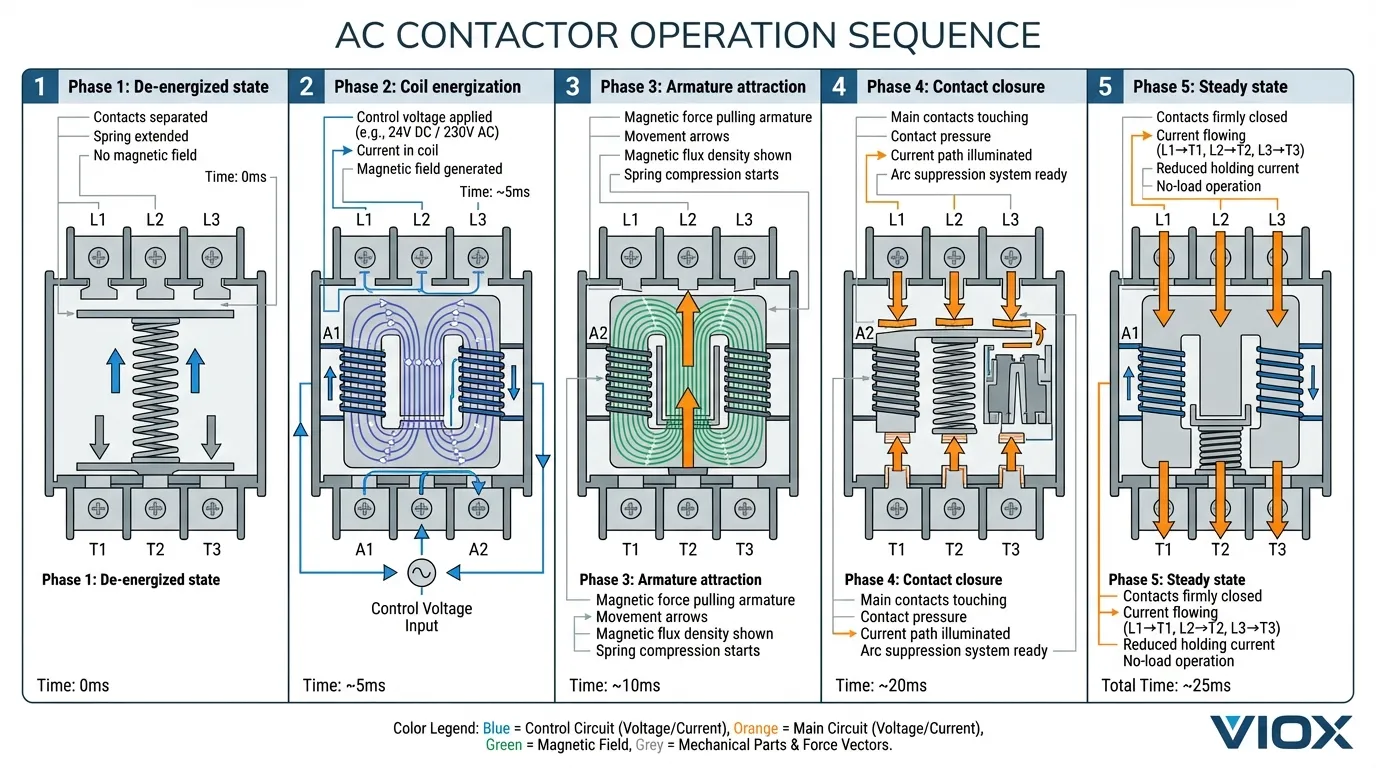
The fundamental operating principle relies on electromagnetic force: apply a low-voltage control signal to the coil, and it generates a magnetic field that mechanically pulls contacts together, enabling current flow to your load. When you de-energize the coil, a spring mechanism instantly separates the contacts—a process that repeats thousands of times daily without operator intervention.
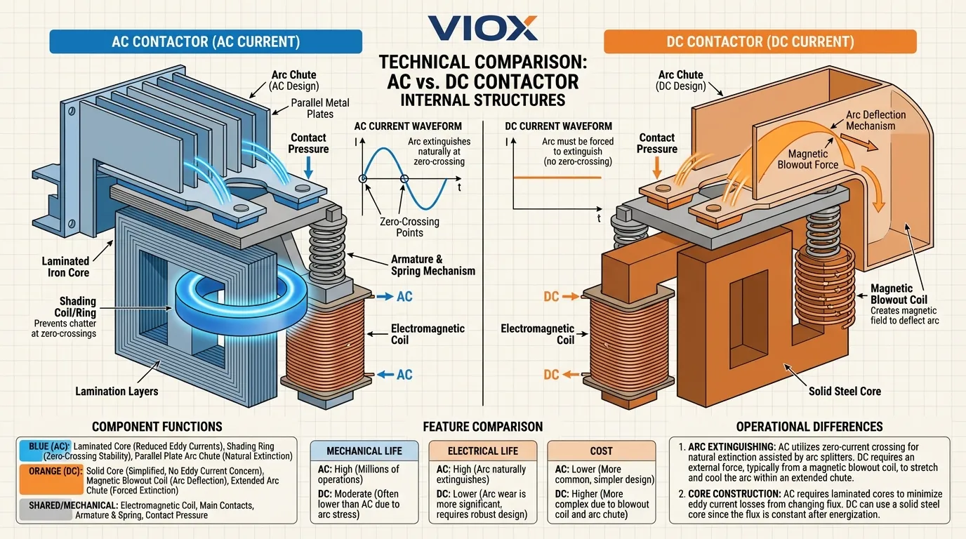
AC contactors are distinct from DC contactors in one critical way: AC current naturally crosses zero 100 to 120 times per second (depending on 50Hz or 60Hz frequency), which simplifies arc extinction. DC contactors must employ additional magnetic blowout coils because DC current provides no natural zero-crossing to extinguish the arc.
The Eight Core Components: Anatomy of an AC Contactor
Every AC contactor, from compact 9A models to industrial 800A+ units, integrates eight essential functional systems:
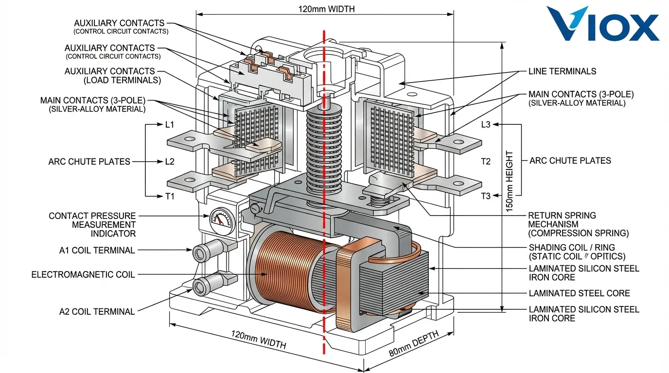
1. Electromagnetic Coil (The Actuator)
Consisting of 1,000-3,000 turns of enameled copper wire wound around a laminated iron core, the coil is the device’s power source. When energized, it generates the magnetic field that actuates the entire mechanism. Coil design is optimized to minimize heat dissipation while maximizing pulling force. Standard ratings include 24V, 110V, 230V, and 380V AC (and equivalent DC levels for DC-rated models).
2. Laminated Iron Core (The Foundation)
Unlike DC contactors using solid steel, AC contactors employ laminated cores—thin steel sheets stacked together—to minimize eddy current losses and hysteresis heating. Lamination thickness typically ranges from 0.35mm to 0.5mm. Higher-performance designs use Cold-Rolled Grain-Oriented (CRGO) steel for superior magnetic properties.
3. Shading Coil/Ring (The AC Secret Weapon)
This small copper loop embedded in the static core face is critical for AC operation. When AC current crosses zero, the primary magnetic field collapses momentarily. The shading ring creates a phase-shifted secondary magnetic flux that maintains attractive force during zero-crossings, preventing the characteristic “chatter” and vibration that would otherwise plague AC contactors.
4. Movable Armature (The Mechanical Link)
The spring-loaded steel plate (laminated in AC models) that responds to magnetic attraction. Travel distance typically ranges from 2-5mm. When the coil energizes, electromagnetic force overcomes spring resistance and pulls the armature toward the static core, mechanically pushing the main contacts together.
5. Main Power Contacts (The Load Path)
These are the business end of the contactor. Typically fabricated from silver-alloy materials, main contacts carry the full load current. Contact pressure—maintained by calibrated springs—ranges from 0.5 to 2.0 N/mm² depending on current rating. Fresh contacts exhibit resistance under 1 milliohm; acceptable service life extends to approximately 5 milliohm before replacement becomes necessary.
6. Arc Chute Assembly (The Safety System)
When contacts separate under load, the collapsing inductive field attempts to maintain current flow, creating an electrical arc. Arc chutes—parallel metal plates arranged like a ladder—divide and cool the arc, increasing the voltage required to sustain ionization until the arc naturally extinguishes at the next current zero-crossing. Arc runners (copper or steel plates) guide the arc away from the main contacts, protecting them from thermal damage.
7. Return Spring Mechanism (The Failsafe)
Calibrated springs ensure the armature instantly returns to its de-energized position when the coil voltage drops. Spring rate selection is critical: too soft and the armature may not fully release; too stiff and the coil may fail to generate sufficient force to close contacts. Many industrial-grade contactors employ dual springs for reliability redundancy.
8. Auxiliary Contacts (The Control Tier)
These smaller contacts (typically rated 6-10A) enable control circuit functionality independent of the main power circuit. Standard configurations include 1NO+1NC (normally open + normally closed), 2NO+2NC, or 4NO. They enable interlocking, status indication, and PLC feedback without interfering with the main circuit.
Materials Engineering: Why Silver Alloys Dominate Contact Systems
Contact Material Selection
The choice of contact material represents one of the most critical engineering decisions in contactor design. Silver dominates industrial applications because of its unmatched electrical and thermal conductivity combined with resistance to welding under arc conditions.
Silver-Nickel (AgNi) accounts for approximately 60% of industrial AC contactors. The nickel addition (10-20% by weight) increases hardness compared to pure silver while maintaining excellent conductivity. This alloy resists contact wear under normal switching duties and offers acceptable performance across AC-1 through AC-4 utilization categories.
Silver-Tin Oxide (AgSnO₂) represents the modern standard for high-performance applications. By incorporating finely dispersed tin oxide particles (typically 5-15%), manufacturers achieve superior resistance to contact welding and electrical erosion. AgSnO₂ is environmentally superior to legacy Silver-Cadmium Oxide (AgCdO), which posed occupational health risks. The oxide particles increase hardness and provide self-healing properties as the contact surface erodes through normal operation.
Iron Core and Lamination Technology
Silicon steel (electrical steel) laminated at 0.35-0.5mm thickness forms the electromagnetic core. The lamination breaks up eddy current paths, reducing core losses by 80-90% compared to solid steel equivalents. Total core losses in a typical 32A AC contactor range from 2-5 watts during operation—significant enough to require thermal management consideration.
Core saturation is carefully engineered: cores are designed to saturate at approximately 1.2-1.5 Tesla flux density during holding operation, ensuring the magnetic pull force remains constant across the 85% to 110% coil voltage tolerance window specified in IEC 60947-4.
Copper Magnet Wire and Insulation
Coil windings employ high-purity oxygen-free copper (typically 99.99% pure) to minimize resistance and heat generation. Wire insulation uses polyesterimide (Class F, 155°C rating) or polyimide (Class H, 180°C rating) to withstand continuous thermal cycling.
Coil thermal rise calculations in a 32A AC contactor operating continuously typically show 40-50°C temperature rise above ambient when properly rated—sufficient to reach 80-90°C absolute temperature in a 40°C environment. This is why ambient temperature derating is essential: every 10°C above 40°C reduces rated current by approximately 10-15%.
Enclosure Materials and Flame Resistance
Housing materials typically include thermoplastic nylon 6 or polyamide compounds with flame-retardant additives meeting UL 94 V-0 requirements. The enclosure must contain internal arc energy without rupturing—a critical safety consideration when internal faults occur. Material thickness and ribbing patterns are optimized to distribute arc pressure while maintaining electrical insulation integrity.
AC Design Logic: Why AC Contactors Work Differently
The Zero-Crossing Advantage
AC current oscillates 100 or 120 times per second (50Hz or 60Hz). This seemingly simple characteristic fundamentally simplifies arc extinction compared to DC systems. When contacts separate during AC operation, the arc naturally extinguishes at the next current zero-crossing—roughly every 10-20 milliseconds. The arc chute system merely needs to cool and lengthen the arc enough to prevent re-ignition.
DC systems face an entirely different challenge: DC current never crosses zero, so the arc continues indefinitely unless forcibly extinguished. This is why DC contactors employ magnetic blowout coils that generate perpendicular magnetic fields to physically push the arc into extended chutes where it stretches, cools, and breaks—an active process requiring additional energy and complexity.
Shading Coil Deep Dive
The shading coil (also called a shading ring or short-circuit ring) represents an elegant engineering solution to a fundamental AC problem. As AC current flows through the main coil, it creates a primary magnetic flux in the core. This flux periodically drops to zero as AC current oscillates. During these zero-crossings, the attractive force on the armature momentarily disappears—if the armature is partially open, this can cause intermittent contact loss or “chatter.”
The shading ring—a single-turn copper loop embedded in the static core face—creates an induced secondary current during flux changes. By Lenz’s law, this induced current generates a phase-shifted secondary magnetic flux that peaks during primary flux zero-crossings. The combined effect maintains roughly constant attractive force across the AC cycle, preventing chatter and enabling smooth, silent operation.
Engineering analysis shows shading rings typically account for 15-25% of holding force during zero-crossings and completely eliminate contact bounce during the closing sequence.
Contact Pressure and Snap Action
AC contactors employ a deliberately non-linear contact closing mechanism. The spring force increases dramatically near full closure (typically 80-100N for a 32A contactor), creating a “snap action” that rapidly accelerates contacts together. This snap action minimizes contact bounce, which would otherwise generate tiny arcs and accelerate contact wear.
The electromagnetic force-versus-travel curve is carefully designed to start at roughly 50% of spring force at maximum air gap, increasing to 150-200% of spring force at full closure. This ensures reliable pickup even at 85% coil voltage while providing stable holding at higher voltages.
Component Performance: Comparative Analysis
| Parameter | AC-1 (Resistive) | AC-3 (Motor Start) | AC-4 (Plugging/Jogging) |
|---|---|---|---|
| Make Current | 1.5× Ie | 6× Ie | 6× Ie |
| Break Current | 1× Ie | 1× Ie | 6× Ie |
| Electrical Life | 2-5M operations | 1-2M operations | 200-500K operations |
| Contact Wear | Minimal | Moderate | High |
| Typical Cost/Unit | $40-80 | $50-120 | $80-180 |
Materials Performance Under Real Conditions
| Material | Application | Advantage | Limitation |
|---|---|---|---|
| AgSnO₂ | High-duty AC-3/AC-4 | Superior welding resistance, environmental compliance | Higher initial cost (+15-25% vs. AgNi) |
| AgNi | General AC-1/AC-2 | Excellent value, proven reliability | Less resistant to heavy switching duty |
| Silicon Steel (Laminated) | Core material | 90% eddy current loss reduction | Requires precise lamination thickness |
| CRGO Steel | Premium cores | 40% higher efficiency | Expensive, premium applications only |
| Copper Windings | Coil | Outstanding conductivity | Requires insulation protection |
| Nylon 6 (FR) | Enclosure | Flame resistant, dimensional stable | Temperature limited to 155-180°C |
Frequently Asked Questions
Q: Why do AC contactors sometimes make a humming sound?
A: Inadequate shading ring design or damaged laminations can cause the attractive force to fluctuate with AC current, creating audible vibration. Proper shading ring design eliminates this—premium AC contactors operate nearly silently.
Q: Can I use a 24V DC coil contactor in place of a 230V AC coil contactor?
A: No. Different coil designs optimize for respective voltage levels. AC coils use laminated cores to minimize eddy losses; DC coils employ solid cores. Always match coil voltage to control circuit voltage.
Q: What causes contact welding?
A: Contact welding typically results from excessive inrush current (voltage transients, capacitor switching), worn contacts with increased contact resistance, or insufficient arc chute design. Proper circuit protection and timely contact replacement prevent welding.
Q: How do I know if my contactor contacts are worn?
A: Contact resistance measurement is the gold standard. Fresh contacts measure <1 mΩ; acceptable service extends to ~5 mΩ. Resistance above 5 mΩ indicates imminent replacement need. Visual inspection may show pitting or cratering of silver surfaces.
Q: Why must AC contactors be laminated while DC contactors don’t need to be?
A: AC current induces eddy currents in the core as the magnetic field changes 100-120 times per second. These eddy currents generate waste heat. Lamination breaks up eddy current paths, dramatically reducing losses. DC current doesn’t change, so solid cores work fine.
Q: What’s the typical mechanical life versus electrical life difference?
A: A typical AC contactor might achieve 10 million mechanical life cycles (unloaded operations) but only 1-2 million electrical life cycles at rated AC-3 current. The difference reflects contact erosion during arcing—a phenomenon that only occurs under load.
Key Takeaways
- AC contactors are precision electromagnetic devices that combine eight specialized subsystems to safely control high-current circuits through millions of switching cycles.
- Material selection is critical: Silver-alloy contacts (AgNi or AgSnO₂), laminated silicon steel cores, and high-purity copper windings define performance boundaries.
- Lamination technology reduces core losses by 80-90% compared to solid cores, making laminated construction essential for AC performance and efficiency.
- The shading coil is the AC contactor’s defining feature, creating phase-shifted secondary flux that maintains contact pressure during AC zero-crossings.
- Arc chute design determines interrupting capability: parallel metal plates cool and divide the arc, enabling safe interruption of fault currents under AC-3 and AC-4 duty cycles.
- Temperature derating is non-negotiable: above 40°C ambient, every 10°C rise reduces continuous current rating by 10-15%.
- Contact material evolution favors AgSnO₂ for modern applications due to superior welding resistance and environmental compliance compared to legacy AgCdO formulations.
- Auxiliary contacts enable complex control logic without interfering with main circuit operation, enabling interlocking, feedback, and status indication functions.
- Utilization categories (AC-1, AC-3, AC-4) define safe application boundaries—oversizing a contactor for AC-3 duty when AC-4 duty exists can lead to premature failure.
- Professional selection requires ten critical parameters: voltage rating, current rating, utilization category, coil voltage, auxiliary contact requirements, mechanical/electrical life, IP rating, ambient temperature, interlock requirements, and cost.
Recommended
- What Is a Contactor? Complete Guide for Electrical Pros — Comprehensive overview of contactor types, applications, and selection methodology
- Contactor vs. Circuit Breaker: The Complete Professional Guide — Essential comparison clarifying when to use contactors for control vs. circuit breakers for protection
- Contactor vs. Motor Starter — Deep dive into motor starter integration and overload relay coordination
- AC-1, AC-2, AC-3, AC-4 Utilization Categories Explained — Technical standards governing safe application ranges
- Modular Contactors: Modern DIN Rail Solutions — Contemporary compact designs for space-constrained installations
- Solar Combiner Box Design with DC Contactors — DC contactor applications in renewable energy systems
