
Direct Answer
Reading a DC isolator switch label correctly comes down to four things, checked in this order:
- Voltage rating — can the switch safely handle the highest DC voltage in your system?
- Current rating — can it carry the expected continuous current without overheating?
- Pole configuration — how many conductors does it disconnect at the same time?
- Utilization category — what kind of DC switching duty was it actually tested for?

The order matters. In practice, the most frequent rating mistakes happen when buyers focus on the ampere number first and overlook the voltage class or utilization category. A 32 A isolator is not automatically suitable for every 32 A DC circuit, especially in solar PV systems, where cold-weather Voc, pole arrangement, and DC switching duty can change the answer completely.
If you need the broader device background first, start with What Is a DC Isolator Switch?. If you already have a label, datasheet, or product spec sheet in front of you, this guide will walk you through what each line means and what to verify next.
Quick Reference Table
| Rating item | What it tells you | Common mistake |
|---|---|---|
| Voltage rating (Ue) | Maximum DC operating voltage the switch can handle under its stated duty | Matching only nominal system voltage and ignoring cold-corrected PV Voc |
| Current rating (Ie) | Current the switch can carry under the specified duty | Assuming the current rating stays the same in every enclosure and temperature condition |
| Poles | How many conductors are disconnected together | Treating 2P and 4P as interchangeable |
| Utilization category | The type of switching duty the device was tested for | Ignoring whether the switch was rated for the actual DC load condition |
| Certification or standard basis | Which market and testing framework the device aligns with | Using AC-marked or vaguely described products in a PV DC application |
Why Reading the Label Matters More Than You Might Expect
A DC isolator switch label is not catalog decoration. It is a compact summary of the conditions under which the device was proven to work safely.
This is especially important in solar PV because:
- the array voltage changes with temperature, and a cold morning can push Voc well above nominal
- the DC side remains energized whenever there is daylight
- DC arcs behave differently from AC arcs, making switching conditions more demanding
- product markings may look similar on the surface while the real application limits differ significantly
With that in mind, the safest approach is to work through each rating one at a time.
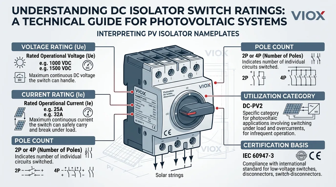
Voltage Rating: Start Here First
The first number to check is the rated DC voltage, often shown as Ue or listed as a maximum DC operating voltage.
What the voltage rating means
The voltage rating tells you the maximum DC system voltage the isolator can handle under the duty for which it was tested. In PV work, this is critical because the device may be used at:
- 600 VDC
- 800 VDC
- 1000 VDC
- 1200 VDC
- or 1500 VDC, depending on the installation architecture
The most common mistake: using nominal voltage instead of maximum corrected voltage
In solar systems, you do not select the isolator based on the nominal DC system label alone. You need the maximum open-circuit voltage, including cold-temperature correction.
Consider this scenario: a PV string is designed for a “1000 V system,” but on a cold winter morning the actual Voc reaches 1050 V. If the isolator is only rated for 1000 VDC, it is effectively under-rated, even though everything looked fine on the quotation sheet.
This is one reason a DC isolator in PV systems should be reviewed with the same engineering discipline as other high-risk DC equipment.
Quick voltage check example
| Scenario | System label | Actual cold-morning Voc | Required minimum Ue |
|---|---|---|---|
| Rooftop PV, temperate climate | 1000 VDC | 1035 V | At least above 1035 VDC, with project margin as required |
| Utility-scale PV, cold region | 1500 VDC | 1540 V | Requires careful string design or a suitably rated higher-voltage solution |
The takeaway is simple: always size the voltage rating against the worst-case corrected Voc, not the system nameplate.
Current Rating: More Than Just an Amp Number
The next item is the current rating, often shown as Ie.
What the current rating means
The current rating tells you how much current the isolator can carry continuously under the conditions defined by the product standard and the manufacturer. In real projects, that number should be checked against:
- expected operating current
- ambient temperature at the installation site
- altitude where relevant
- enclosure heating effects
- conductor grouping
- installation orientation, if specified by the manufacturer
Why current rating alone does not tell the full story
Two isolators both labeled 32 A may not be equally suitable in every situation.
| Factor | Isolator A (32 A) | Isolator B (32 A) |
|---|---|---|
| Enclosure type | Ventilated indoor panel | Sealed outdoor PV combiner box, 55 °C ambient |
| Utilization category | DC-21B | DC-PV2 |
| Pole configuration | 2P | 4P |
| Practical suitability for a 30 A rooftop PV string | May need derating due to temperature | May be more suitable, pending full design review |
The point is not that one is always better than the other. It is that current should always be read alongside voltage and utilization category, not in isolation.
Poles: What 2P and 4P Actually Mean
Pole configuration tells you how many conductors the switch opens at the same time.
2-pole isolator
A 2P DC isolator is commonly used where one positive and one negative conductor are disconnected together for a single string or single DC circuit.
4-pole isolator
A 4P DC isolator is commonly used in applications where two strings or a different conductor arrangement are being disconnected with one device, or where the internal switching path is configured to manage higher DC voltage using series-connected poles.
Why the pole count deserves more attention than it usually gets
It is easy to think of poles as a simple wiring convenience. In practice, pole count can affect:
- how conductors are actually interrupted
- the maximum usable voltage, where series-connected poles may extend capability
- internal contact configuration
- the accepted wiring method
A 4-pole switch is not simply “a bigger 2-pole switch.” The manufacturer’s connection diagram still determines how the poles should be wired, and getting this wrong can create safety issues.
If wiring method is your main question, the next relevant page is Connection of DC Isolators.
Utilization Category: The Rating Most People Skip and Shouldn’t
This is one of the most important lines on a DC isolator spec sheet and one of the most overlooked.
What utilization category means, in plain language
Think of utilization category as the test scenario the switch went through before it was allowed to carry that label. Under IEC 60947-3, every DC isolator is tested against a specific switching duty, meaning a defined combination of voltage, current, load type, and number of switching operations.
The utilization category printed on the label tells you which test scenario the switch passed. In practical terms, it answers:
- was this switch tested only for basic, well-behaved resistive loads?
- or was it tested for more demanding conditions involving inductive loads or photovoltaic-specific behavior?
General DC categories: DC-21B and DC-22B
At a simplified level:
- DC-21B covers resistive or slightly inductive DC loads
- DC-22B covers mixed resistive and inductive switching conditions
If your application involves straightforward resistive DC loads, DC-21B may be sufficient. For more demanding mixed-load conditions, DC-22B gives a stronger basis.
PV-specific categories: DC-PV1 and DC-PV2
When the application is specifically solar PV, two additional categories become highly relevant:
- DC-PV1 is associated with standard PV switching duty, where significant overcurrents are not expected to dominate the switching event
- DC-PV2 is associated with more demanding photovoltaic switching conditions, including cases where reverse current flow or more severe overcurrent conditions may be present
In many rooftop and commercial PV projects, designers prefer DC-PV2 because it aligns better with more demanding photovoltaic switching scenarios. The final choice, however, should still follow the actual project architecture and switching duty.
A practical comparison
| Application | Minimum recommended category | Why |
|---|---|---|
| Simple DC resistive load, industrial panel | DC-21B | Load is predictable, with no PV-specific behavior |
| DC motor circuit | DC-22B | Inductive load creates more demanding switching conditions |
| Rooftop PV string isolator | DC-PV1 or DC-PV2 | PV-specific duty; DC-PV2 is often preferred where switching conditions are more demanding |
| Utility-scale PV with parallel strings | Often DC-PV2 | Reverse-current paths and higher fault energy usually justify the more demanding PV duty |
Why this matters when you compare products
A buyer may see two isolators side by side:
- Product X:
1000 VDC, 32 A, 4P, DC-21B - Product Y:
1000 VDC, 32 A, 4P, DC-PV2
The voltage, current, and pole count are identical. But Product X was tested for a general resistive DC duty, while Product Y was tested specifically for photovoltaic switching conditions. For a PV application, Product Y is often the more appropriate choice, even though Product X might appear equivalent at first glance.
The utilization category is often the line that separates a sound engineering choice from a superficial catalog match.
How to Read a Real Example Label
Imagine you are looking at a DC isolator marked like this:
1000 VDC, 32 A, 4P, IEC 60947-3, DC-PV2
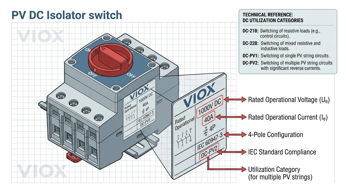
Here is what each element tells you:
1000 VDC— the switch is intended for DC systems up to 1000 V under the stated duty32 A— it can carry up to 32 A continuously under its defined conditions4P— it uses four poles, which may be required by the internal switching arrangement or the circuit architectureIEC 60947-3— the switch is aligned with the relevant IEC switch-disconnector standardDC-PV2— the switch was tested for a more demanding photovoltaic switching duty
The engineering follow-up
Reading the label is only the first step. The correct follow-up questions are:
- what is my actual maximum system voltage, including cold-temperature correction?
- what conductor arrangement am I disconnecting, and does the pole configuration match?
- what is the real load condition: resistive, inductive, or PV-specific?
- is this utilization category actually appropriate for this switching duty?
Rating Selection Decision Flow
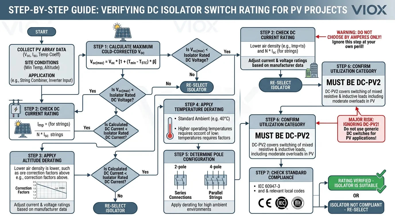
When selecting a DC isolator, working through the ratings in a structured sequence helps avoid the most common pitfalls.
Step 1: Determine your maximum DC voltage
Calculate the worst-case open-circuit voltage for your system, including cold-temperature correction. This number becomes your minimum voltage requirement.
Step 2: Confirm the voltage rating (Ue)
Check that the isolator meets or exceeds that number. If it does not, the device is disqualified regardless of any other rating.
Step 3: Verify the current rating (Ie)
Check the expected operating current, ambient temperature, altitude, enclosure type, and any derating factors specified by the manufacturer.
Step 4: Check the pole configuration
Confirm that the number of poles matches your circuit architecture and the manufacturer’s recommended wiring diagram.
Step 5: Verify the utilization category
For PV applications, look for DC-PV1 or DC-PV2. For general DC applications, confirm that DC-21B or DC-22B matches the load type. If the utilization category is missing or unclear, treat that as a red flag.
Step 6: Confirm the standard and certification basis
The device should reference IEC 60947-3 or another applicable regional standard basis, such as UL 98B in the North American photovoltaic context.
If the device passes all six checks, it can move to the detailed engineering review. If it fails at any step, go back to the product selection stage.
Common Reading Mistakes and How to Avoid Them
Mistake 1: Looking at current first
This is the most common commercial mistake. A 32 A device gets approved for a project even though the voltage class or switching duty does not match the actual system.
How to avoid it: always start with voltage. Current is important, but it only matters after voltage suitability is confirmed.
Mistake 2: Ignoring the utilization category
A switch with the right current and voltage can still be unsuitable if the utilization category does not match the actual DC duty.
How to avoid it: treat the utilization category as a mandatory selection criterion, not an optional data point.
Mistake 3: Assuming more poles automatically means better
More poles do not automatically mean a safer or more capable switch. They indicate a specific internal and external conductor interruption arrangement.
How to avoid it: always refer to the manufacturer’s connection diagram and confirm how the poles should be wired for your specific circuit layout.
Mistake 4: Treating AC-looking markings as acceptable for DC
Some products carry markings that appear generic or are mainly associated with AC applications. If the device is not clearly rated and identified for DC switching duty, proceed with caution.
How to avoid it: look for explicit DC voltage markings, a DC utilization category, and reference to IEC 60947-3 or another applicable DC-relevant standard basis.
FAQ
What is the first rating I should check on a DC isolator switch?
Start with the voltage rating, because a switch that is under-rated for DC voltage is immediately disqualified regardless of its current rating. In PV applications, check against the cold-corrected maximum Voc, not just the nominal system voltage.
What does 4P mean on a DC isolator switch?
It means the switch uses four poles to disconnect the circuit. In DC applications, this often affects how the conductors are routed and what voltage arrangement the switch can support.
What does DC-21B mean?
It is an IEC utilization category indicating the switching duty for which the device was tested. DC-21B corresponds to resistive or slightly inductive DC loads.
What do DC-PV1 and DC-PV2 mean on a solar isolator switch?
They are photovoltaic-specific utilization categories used in the IEC 60947-3 framework. DC-PV1 covers standard PV switching duty, while DC-PV2 covers more demanding PV conditions, including reverse-current scenarios.
Is current rating more important than utilization category?
No. Current rating tells you how much load the switch can carry. Utilization category tells you what kind of load and switching conditions the switch was designed to handle.
Can I choose a DC isolator by amperes only?
No. A correct selection also depends on maximum DC voltage, pole configuration, utilization category, and the specific application conditions.
What to Do Next
Now that you understand how to read the ratings, the next step is to apply them to your actual project.
- If you are selecting an isolator for a specific project, use the six-step decision flow above to verify each candidate against your real system parameters.
- If you need help with the wiring side, continue to Connection of DC Isolators for pole-by-pole wiring guidance.
- If you want to review VIOX DC isolator specifications, visit the DC Isolator Switch product page to compare voltage, current, pole, and utilization category data.
- If you need the broader fundamentals, go back to What Is a DC Isolator Switch?.
