Introduction
Electrical safety in industrial and commercial installations isn’t about choosing between protection methods—it’s about understanding how they work together. Many facility managers and contractors face a common question: “Don’t these devices do the same thing?” The answer reveals a fundamental truth about electrical protection.
Grounding, GFCI (Ground Fault Circuit Interrupter) or RCD (Residual Current Device), and surge protection devices each address distinct failure modes in your electrical system. They’re not redundant; they’re complementary layers that protect against different threats. A properly grounded system won’t save your equipment from lightning-induced voltage spikes. A surge protector won’t prevent someone from being electrocuted by a ground fault. And an RCD can’t stabilize voltage during normal operation.
This guide breaks down each protection pillar, explains what it protects against (and what it doesn’t), and shows you how to specify a complete safety system that meets IEC and NEC standards while protecting both personnel and equipment.
Pillar 1: Grounding Systems
What Grounding Does
Grounding (or earthing) creates a deliberate, low-impedance connection between your electrical system and the earth. Think of it as the foundation of electrical safety—without it, the other two pillars can’t function properly.
The grounding system connects all non-current-carrying metal parts of your installation—equipment enclosures, raceways, and structural metal—to a grounding electrode buried in the earth. This provides a safe path for fault current to flow.
How Grounding Protects
Personnel Safety: When a fault energizes equipment enclosures (a loose wire touches the metal casing), the ground conductor provides a low-resistance path to earth. This prevents dangerous touch voltages and ensures rapid fault current flow to trip overcurrent devices.
Fire Prevention: By channeling fault currents safely, grounding prevents wire overheating and arcing that can ignite fires. The high fault current triggers circuit breakers or fuses, isolating the problem.
Voltage Stabilization: Grounding establishes a reference point for your electrical system, maintaining stable voltage during normal operation. This is critical for sensitive industrial control equipment.
Overvoltage Protection: Lightning strikes and utility line surges need a path to earth. Grounding provides this path, though it requires coordination with surge protection devices for complete protection.
IEC 60364 and NEC Article 250 Requirements
International standards classify grounding systems by how the source and installation relate to earth:
| System Type | Source Connection | Exposed Parts Connection | Common Applications |
|---|---|---|---|
| TN-S | Neutral directly earthed | Connected via separate PE conductor | Most common in new industrial installations |
| TN-C-S | Combined PEN conductor, later separated | Connected to PEN, then separate PE | Building service entrance configurations |
| TT | Source earthed | Independent local earth electrode | Required where utility grounding unavailable; needs RCD |
| IT | Isolated or high-impedance earth | Local earth connection | Hospitals, critical processes requiring continuity |
NEC Article 250 mandates grounding for systems over 50V. Key requirements include:
- Grounding electrode system: Metal water pipes, building steel, concrete-encased electrodes (Ufer ground), and ground rods must bond together
- Equipment grounding conductors (EGC): Required in all circuits, sized per Table 250.122 based on overcurrent device rating
- Effective ground-fault current path: Must be permanent, continuous, and low-impedance. The earth alone is not an effective ground-fault path.
What Grounding Cannot Do
Doesn’t detect current leakage: A person touching a live conductor while standing on an insulated surface won’t be protected—there’s no path to ground for the grounding system to sense. This is where RCDs are essential.
Doesn’t limit transient overvoltages: While grounding provides a path for surge current, it doesn’t clamp voltage to safe levels. You need SPDs for that.
Doesn’t prevent all shocks: If you contact both live and neutral simultaneously, the current doesn’t flow through ground, so the system sees balanced current and doesn’t trip.
Pillar 2: GFCI/RCD Protection
What RCDs Do
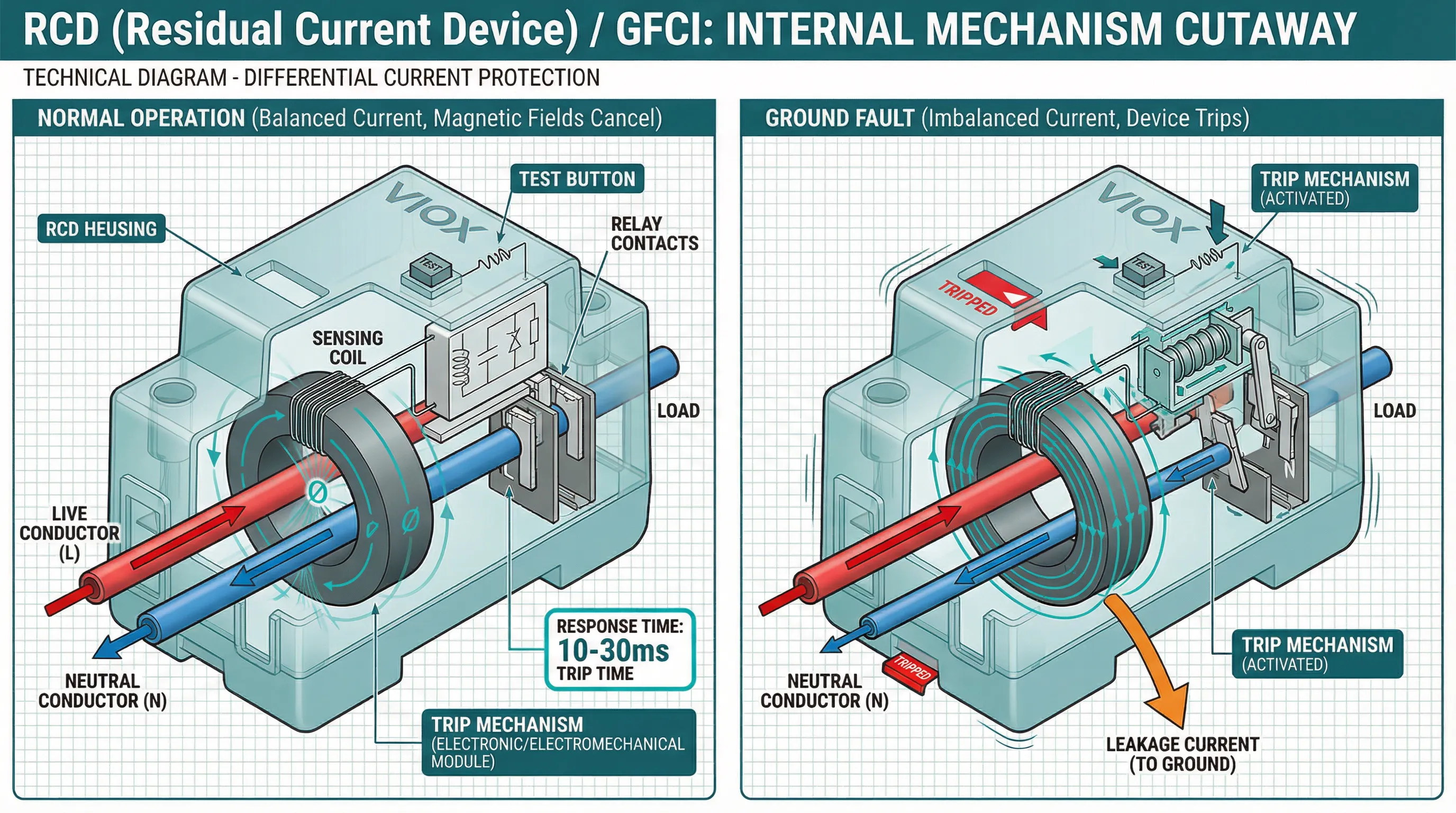
Residual Current Devices (RCDs)—called Ground Fault Circuit Interrupters (GFCIs) in North America—are life-saving devices designed specifically to protect people from electric shock. They monitor current balance and react in milliseconds to dangerous leakage.
Unlike grounding, which provides a passive fault path, RCDs actively monitor the circuit and trip the moment they detect current flowing through an unintended path, such as a person’s body.
How RCDs Work
An RCD uses a differential current transformer (core balance transformer) with both live and neutral conductors passing through it. In normal operation, current flowing out through the live conductor equals current returning through the neutral. The magnetic fields cancel out.
When a ground fault occurs—someone touches a live part, or insulation fails—current leaks to ground. This creates an imbalance. The sensing coil detects this difference, induces a current in the secondary winding, and trips the relay mechanism. The entire process takes 10-30 milliseconds.
Sensitivity and Response Time
IEC 61008 defines RCD sensitivity by rated residual operating current (IΔn):
| Sensitivity Class | IΔn Rating | Typical Application | Tripping Time |
|---|---|---|---|
| High-sensitivity | 5 mA, 10 mA, 30 mA | Personnel protection, additional protection against direct contact | 10-30 ms typical; 300 ms maximum |
| Medium-sensitivity | 100 mA, 300 mA, 500 mA, 1000 mA | Fire protection in industrial installations | Per IEC 61008 time-current curve |
| Low-sensitivity | 3 A, 10 A, 30 A | Machinery protection, equipment isolation | Application-specific |
For personnel protection, 30 mA is the standard. This threshold is low enough to prevent ventricular fibrillation in healthy adults while high enough to avoid nuisance tripping from normal leakage in large installations.
RCD Types per IEC 61008/61009
Type AC: Detects sinusoidal AC residual currents only. Suitable for resistive loads like heating and lighting.
Type A: Detects both AC and pulsating DC residual currents. Required for modern electronics, variable-speed drives, and rectifier-based loads that can produce DC fault components.
Type B: Detects AC, pulsating DC, and smooth DC residual currents. Mandatory for EV charging stations, solar inverters, and industrial frequency converters per IEC 61851 and IEC 62196.
Type F: Enhanced Type A with immunity to high-frequency interference. Used for IT equipment and motor control centers.
What RCDs Cannot Do
No protection for line-to-line contact: If someone simultaneously touches both live and neutral, the RCD sees balanced current and won’t trip. The current doesn’t leak to ground.
No overcurrent protection: RCDs don’t protect against overloads or short circuits. They must be installed downstream of MCBs or MCCBs, or use RCBOs (combined devices).
No surge protection: RCDs detect current imbalance, not voltage spikes. A lightning surge can damage equipment even with RCD protection.
Requires functioning supply: Standard RCDs need line voltage to operate the trip mechanism. Voltage-independent types exist for critical applications.
Pillar 3: Surge Protection Devices
What SPDs Do
Surge Protection Devices (SPDs) protect equipment from transient overvoltages—brief but destructive voltage spikes caused by lightning, utility switching, or load changes. These surges can reach thousands of volts and destroy sensitive electronics in microseconds.
SPDs detect excess voltage and divert it to the grounding system, clamping the voltage to a safe level. This is why proper grounding is essential—without a low-impedance path to earth, the SPD has nowhere to send the surge energy.
How SPDs Work
SPDs use three primary technologies:
Metal Oxide Varistors (MOVs): Semiconductor devices with voltage-dependent resistance. At normal voltage, they’re essentially open. When voltage exceeds the threshold, resistance drops dramatically, shunting the surge to ground. Response time: <25 nanoseconds.
Gas Discharge Tubes (GDTs): Gas-filled ceramic tubes that ionize and conduct at high voltage. Handle massive surge currents but have slower response (microseconds) and higher clamping voltage. Often used in telecom protection.
Suppression Diodes (SAD/TVS): Fast-acting semiconductor devices for low-voltage, precision protection. Common in data lines and sensitive control circuits.
Industrial SPDs often combine technologies: GDTs for high-energy strikes, MOVs for medium surges, and diodes for final clamping.
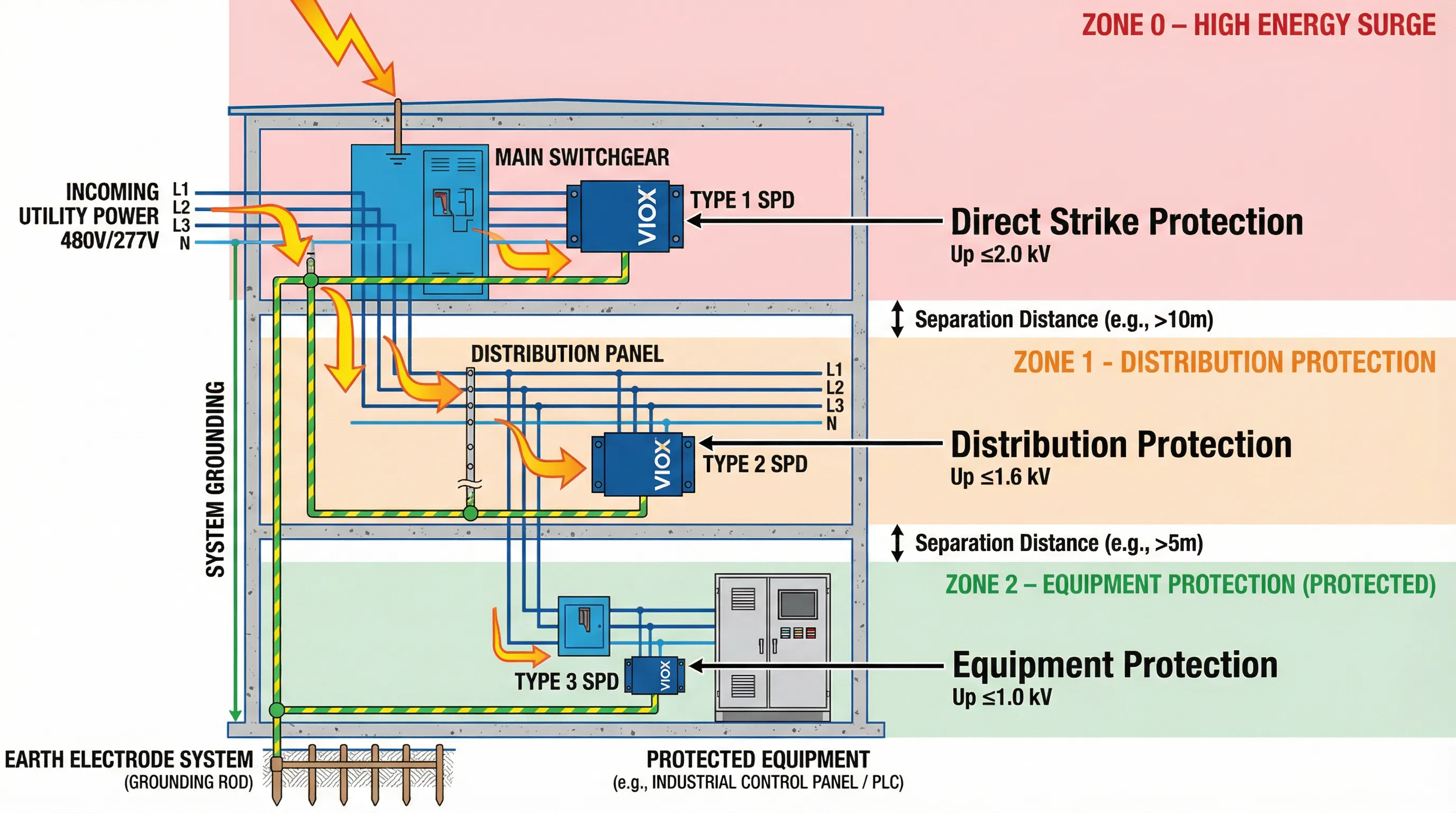
IEC 61643 Classification
IEC 61643-11 defines three SPD types for coordinated protection:
| SPD Type | Installation Location | Test Waveform | Impulse Current (Iimp) | Nominal Discharge (In) | Voltage Protection Level (Up) | Purpose |
|---|---|---|---|---|---|---|
| Type 1 (Class I) | Main service entrance, upstream of main breaker | 10/350 µs | 10-200 kA | — | 1.5-2.0 kV | Direct lightning strike protection |
| Type 2 (Class II) | Distribution panels, sub-panels | 8/20 µs | — | 10-60 kA | ≤1.6-2.0 kV | Indirect lightning, switching surges |
| Type 3 (Class III) | Point-of-use, near equipment | 1.2/50 µs (Uoc) + 8/20 µs (In) | — | <5 kA | 1.0-1.5 kV | Final protection for sensitive equipment |
Coordinated installation is critical. Type 1 handles the massive energy from direct strikes. Type 2 protects against surges that penetrate past the service entrance. Type 3 provides final clamping for sensitive loads.
Key Specifications
Voltage Protection Level (Up): The maximum voltage the SPD allows to pass through. Must be lower than the equipment’s impulse withstand voltage. For 230V systems with equipment rated for 2.5 kV impulse withstand, specify SPDs with Up ≤ 2.0 kV.
Nominal Discharge Current (In, 8/20 µs): The current the SPD can handle repeatedly. Industrial applications typically require 20-40 kA for Type 2 devices.
Maximum Discharge Current (Imax): The peak current for a single surge event. Important for high-exposure installations.
Response Time: MOV-based SPDs react in nanoseconds, fast enough for most threats. GDT-based devices take microseconds but handle higher energy.
Installation Requirements
Per IEC 61643-11:
- Lead length <0.5 meters: Long leads create inductance, increasing effective Up and negating protection
- Backup overcurrent protection: Fuses or circuit breakers protect against SPD failure
- Proper grounding: SPD effectiveness depends entirely on grounding system impedance
- Coordination between types: Type 1 and Type 2 SPDs need minimum 10-meter cable separation or decoupling inductance
What SPDs Cannot Do
No personnel shock protection: SPDs protect equipment from overvoltage, not people from electric shock. They won’t trip if someone touches a live conductor.
No protection without grounding: An SPD diverts surge current to ground. If your grounding system has high impedance or is disconnected, the SPD is useless.
No protection against sustained overvoltage: SPDs handle transients lasting microseconds to milliseconds. They can’t protect against long-duration overvoltage from utility issues—you need over/under voltage relays for that.
Finite lifespan: SPDs degrade with each surge. Most include visual indicators or remote contacts to signal end-of-life.
Comparison Table
| Protection Feature | Grounding System | GFCI/RCD | Surge Protection Device (SPD) |
|---|---|---|---|
| Primary Purpose | Fault current path, voltage reference | Personnel shock protection | Equipment protection from transients |
| What It Protects Against | Equipment faults, fire, enables overcurrent device operation | Electric shock from ground faults (4-30 mA leakage) | Lightning, switching surges, voltage spikes |
| What It Does NOT Protect Against | Current leakage <circuit breaker threshold, voltage spikes, line-to-line shock | Overload, short circuit, voltage surges, line-to-line contact | Shock hazards, overcurrent, sustained overvoltage |
| Response Time | Instantaneous (path always present) | 10-30 ms typical, 300 ms max | <25 ns (MOV), 1-5 µs (GDT) |
| Activation Threshold | N/A (passive conductor) | 5 mA to 30 A (depends on rating) | Exceeds rated voltage (e.g., >350V for 230V system) |
| Key Standards | IEC 60364, NEC Article 250 | IEC 61008/61009, NEC 210.8 | IEC 61643-11, UL 1449 |
| Installation Location | Throughout system: service, panels, equipment | Distribution boards, circuits with shock risk (wet areas, equipment) | Service entrance (Type 1), panels (Type 2), equipment (Type 3) |
| Requires Other Protection | No, but enables others to work | Yes — needs upstream MCB/MCCB | Yes — requires grounding and backup fuse/breaker |
| Typical Industrial Ratings | <1 Ω electrode resistance; EGC per NEC Table 250.122 | 30 mA (personnel), 100-300 mA (fire), Type A/B for industrial | Type 2: 20-40 kA In; Up ≤2.0 kV |
| Maintenance | Periodic resistance testing | Monthly test button, annual trip test | Visual indicator check, replacement after major surge |
| Failure Mode | Gradual corrosion; detectable via testing | Fail-safe (most trip on failure); test quarterly | Degradation after surges; monitor indicator |
| Cost Consideration | Moderate; design/installation cost | Low-moderate per device | Moderate (Type 2) to high (Type 1) |
| Code Requirements | Mandatory per NEC/IEC for all systems >50V | Mandatory for wet/outdoor locations, machinery per IEC 60204 | Recommended for critical equipment; mandatory for lightning-prone areas |
FAQ Section
Q: Can I skip grounding if I have RCDs and surge protectors?
No. Grounding is the foundation. RCDs detect current imbalance by comparing live and neutral—they need a ground reference to function. Surge protectors divert excess voltage to ground; without a proper grounding system, they have nowhere to send the energy. All three work together.
Q: Will a surge protector prevent electric shock?
No. Surge protectors address equipment damage from voltage spikes, not personnel safety. If someone touches a live conductor, the surge protector won’t react because there’s no voltage surge—just normal current taking an unintended path through a person. That’s what RCDs prevent.
Q: Do I need Type B RCDs for all industrial installations?
Not all, but increasingly common. Type B RCDs are mandatory for loads that can produce DC fault currents: EV chargers, solar inverters, variable frequency drives, and regenerative braking systems. For standard resistive and inductive loads, Type A is sufficient. Check IEC 60204-1 for machinery requirements.
Q: How do I know when to use Type 1 vs. Type 2 SPDs?
Installation location determines this. Type 1 goes at the main service entrance if you have external lightning protection or are in a high-exposure area. Type 2 installs at distribution panels and sub-panels—this is the most common industrial SPD. Use both in coordinated protection for comprehensive coverage.
Q: Can RCDs cause nuisance tripping in large installations?
Yes, if sensitivity is too high. Large installations have cumulative leakage current from cable capacitance and filter circuits. For a 400A industrial panel, specify 300 mA RCDs for fire protection rather than 30 mA. Use 30 mA only for final circuits with direct personnel contact risk. Time-delayed S-type RCDs prevent nuisance trips from transient leakage.
Q: What’s the difference between grounding and bonding?
Grounding connects your electrical system to earth. Bonding connects all non-current-carrying metal parts together—enclosures, raceways, structural steel—to eliminate dangerous potential differences. Both are required. NEC Article 250 covers both; IEC 60364-5-54 addresses bonding specifically.
Conclusion
Electrical safety isn’t a single device or code requirement—it’s a system where grounding, GFCI/RCD protection, and surge protection work as complementary layers. Each addresses specific failure modes that the others cannot prevent.
Grounding provides the foundation: a fault current path, voltage reference, and the essential infrastructure for other protection devices to function. RCDs save lives by detecting current leakage in milliseconds, protecting personnel from shock hazards that grounding alone cannot prevent. Surge protectors shield equipment investments from transient overvoltages that would otherwise destroy sensitive electronics.
When specifying electrical protection for industrial or commercial installations, the question isn’t “which one?” but “how do I integrate all three?” Design for coordinated protection: proper grounding per NEC Article 250 or IEC 60364, RCDs on circuits with shock risk per IEC 61008/61009, and multi-stage SPD coordination per IEC 61643-11.
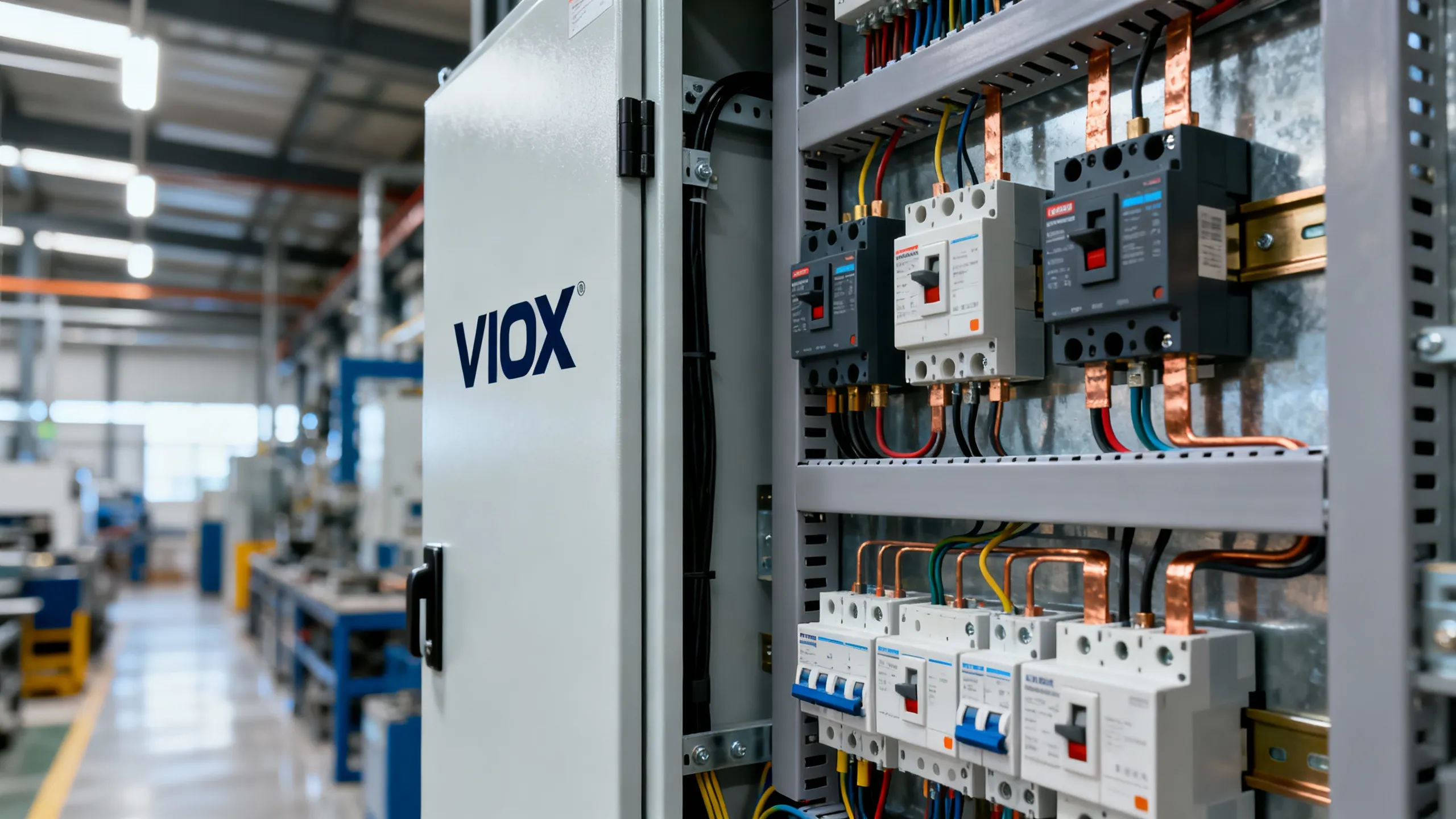
At VIOX Electric, we manufacture industrial-grade RCDs, surge protection devices, and complete protection solutions engineered to work together. Our technical team can help you specify the right combination for your application, ensuring compliance with international standards while protecting both personnel and equipment.
