
Adecuado 12V fusible de colocación el plazo de 7 pulgadas de la batería terminal positivo para la seguridad automotriz

Colocar fusibles en el plazo de 7 pulgadas de fuentes de alimentación.
No es una sugerencia—es la diferencia entre un fusible quemado y un cableado de fuego.
Cómo Elegir El Correcto Tamaño de Fusible Para Su Sistema Eléctrico de 12V | de 12 Voltios Planeta
El Hilo De Su Sistema De Derecho (Y Mantenerlo De Esa Manera)
El fusible es El Alambre de Tutor de tamaño para proteger el cable, compruebe que el cable puede controlar el fusible, colocarlo dentro de 7 pulgadas de la fuente de alimentación.
Lista de comprobación rápida antes de energizar un circuito: – ✓ Dispositivo actual calculado (Vatios ÷ 12V = Amperios) – ✓ 125% que se aplica (o 250% para motores)
– ✓ Cable de corriente admisible marcada (fusible ≤ clasificación del cable) – ✓ Fusible colocado dentro de los 7" de la fuente de alimentación – ✓ Adecuado tipo de fusible seleccionado para el nivel actual
– ✓ Todas las conexiones plegado correctamente y terminales para la corriente nominal Recuerde que $800 estéreo fuego de la apertura? He aquí cómo debería haber hecho: 12-amplificador estéreo, 15A fusible (12A × 1.25), 16 AWG (22A calificación), la caja de fusibles situada a 6 pulgadas desde el positivo de la batería. Capacidad de cable supera la intensidad nominal del fusible. El fusible se encuentra dentro de 7 pulgadas. Si que los tornillos de montaje de obras sueltas y pantalones cortos del alambre, el fusible se funde en milisegundos—mucho antes de que el alambre se calienta lo suficiente como para derretir cualquier cosa. El costo Total para hacer lo correcto: $18 para la correcta alambre, $2 para el correcto fusible, 15 minutos adicionales de tiempo de instalación.
- El costo Total para hacerlo mal: $2,800 y explicando a un ajustador de seguros por qué pensabas que un fusible de 30A en alambre calibre 18 era una buena idea. son las más baratas de seguro en su sistema eléctrico.
- El tamaño de ellos basado en la capacidad de cable, no una ilusión. El Alambre Tutor sólo funciona si vamos a hacer su trabajo. Arranque y funcionamiento del motor de jaula de ardilla. Soporta 6 veces la corriente de entrada al cierre, interrumpe a la corriente de funcionamiento.
- AC-4: Servicio severo: inversión de marcha, frenado por contracorriente, impulsos. Cierra e interrumpe hasta 6 veces la FLA.
Un interruptor clasificado como “20A” para servicio AC-1 podría manejar solo un motor de 5 HP en servicio AC-3. El amperaje nominal por sí solo no le dice nada sobre la capacidad de control del motor.
Conclusión Clave: Los contactos del interruptor, el diseño de supresión de arco y la durabilidad mecánica difieren entre un interruptor “de uso general de 20A” y un interruptor “de control de motor AC-3 de 20A”. Siempre verifique la categoría de utilización antes de seleccionar.
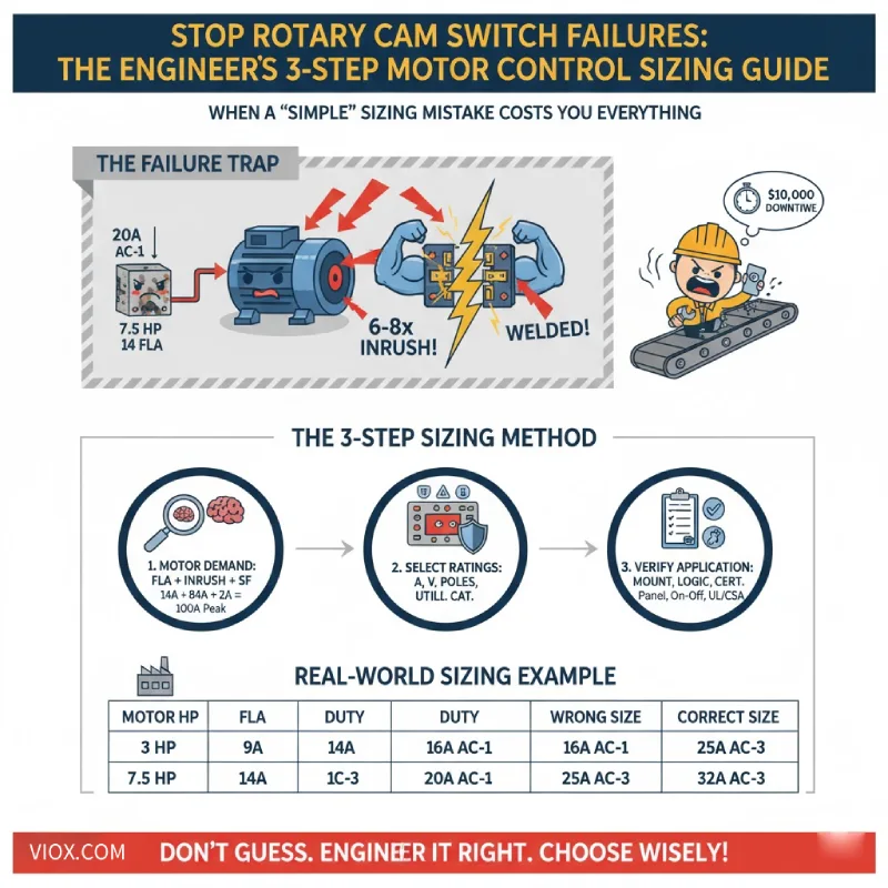
El método de 3 pasos Interruptor de leva giratorio Método de dimensionamiento


Siga este proceso sistemático para especificar un interruptor que maneje el estrés eléctrico real del control del motor, no solo los números teóricos de la placa de identificación.
Paso 1: Calcule la verdadera demanda eléctrica de su motor
No se limite a copiar la FLA de la placa de identificación del motor y darlo por terminado. Necesita comprender el perfil eléctrico completo de su motor:
1.1 Comience con el amperaje a plena carga (FLA)
Encuentre esto en la placa de identificación del motor a su voltaje nominal. Por ejemplo:
- 3 HP a 208V = ~9A
- 7.5 HP a 415V = 10-14A
- 15 HP a 480V = 20-22A
1.2 Tenga en cuenta el método de arranque
La forma en que arranca el motor afecta drásticamente el estrés del interruptor:
- Arranque directo (DOL): La corriente de entrada total golpea el interruptor. Más exigente al cierre.
- Estrella-Triángulo: Menor corriente de entrada, pero dos operaciones de conmutación por arranque.
- Arrancador suave/VFD: Aumento controlado, pero aún necesita conmutar la corriente de funcionamiento completa.
1.3 Considere el factor de servicio
Si su motor funciona continuamente o cerca de la carga máxima, aplique un factor de servicio. Muchos ingenieros usan 1.15x a 1.25x FLA como la corriente de diseño.
Pro Tip: Para un motor de 7.5 HP a 415V que consume 14A FLA con arranque DOL, su interruptor debe manejar 14A continuos más 80-100A de corriente de entrada durante varios segundos. Esto le dice inmediatamente que un interruptor de 16A es de tamaño insuficiente; necesita al menos 25A clasificados para servicio AC-3.
Paso 2: Seleccione el interruptor con las clasificaciones correctas
Ahora haga coincidir el perfil de su motor con un interruptor que pueda manejarlo. Está verificando cuatro especificaciones críticas:
2.1 Clasificación de corriente (siempre redondee hacia arriba)
Seleccione un interruptor con una clasificación de corriente igual o mayor que la corriente de funcionamiento máxima de su motor—con margen.
| HP del motor | Voltaje | Amperios a plena carga | Amperaje del interruptor sugerido |
|---|---|---|---|
| 3 HP | 208 V | ~9A | 16 A |
| 7.5 HP | 415 V | ~10-14A | 25 A |
| 15 HP | 480 V | ~20-22A | 25-32 A |
Conclusión Clave: Redondee al tamaño de interruptor estándar más cercano. Si su motor consume 22A, elija 25A o 32A, nunca 20A. Este margen protege contra la caída de tensión durante el arranque y proporciona margen térmico para el servicio continuo.
2.2 Clasificación de voltaje (cumplir o exceder)
La clasificación de voltaje del interruptor debe ser igual o superior al voltaje de suministro de su motor:
- Motor de 400V → interruptor mínimo de 400V
- Motor de 480V → interruptor de 480V o 600V
- Nunca use un interruptor de 400V en un circuito de 480V
2.3 Configuración de polos
Haga coincidir los polos con la configuración de fase de su motor:
- Motores monofásicos: Interruptor de 2 polos (ambos conductores de línea conmutados)
- Motores trifásicos: Interruptor de 3 polos (las tres fases se conmutan simultáneamente)
Crítico: No use un interruptor de un solo polo para controlar un motor trifásico conmutando solo una fase. Esto crea un desequilibrio de fase y puede destruir el motor.
2.4 Categoría de utilización (la especificación oculta)
Aquí es donde los ingenieros se queman. Verifique que el interruptor esté clasificado para su servicio específico:
- Arranque/parada DOL estándar: AC-3 mínimo
- Inversión, frenado por contracorriente o control de múltiples velocidades: AC-4 requerido
- Conmutación de encendido y apagado solamente (sin servicio de arranque): AC-3 es suficiente
Un interruptor clasificado como “25A AC-1” podría manejar solo 12A en servicio AC-3. Siempre verifique la tabla de clasificaciones de control de motores del fabricante; no asuma que se aplica la clasificación nominal.
Paso 3: Verifique los requisitos específicos de la aplicación
Tiene las clasificaciones eléctricas correctas. Ahora confirme las especificaciones físicas y ambientales:
3.1 Montaje y Gabinete
- Montaje en panel: Frontal de puerta con manija de operador
- Riel DIN: Ahorro de espacio para paneles de control densos
- Encerrado: IP65/NEMA 4 para entornos polvorientos o de lavado
3.2 Lógica de control y posiciones
- 2 posiciones (Encendido-Apagado): Arranque/parada simple
- 3 posiciones (Apagado-1-2): Motores de dos velocidades, transición estrella-delta
- Retorno por resorte a cero: Contacto mantenido para marcha, momentáneo para avance lento
- Con posibilidad de candado: Bloqueo/etiquetado de seguridad para mantenimiento
3.3 Certificación y Cumplimiento
Verifique que el interruptor tenga certificaciones para su jurisdicción:
- América del Norte: Listado UL/CSA
- Europa: Cumple con IEC/EN 60947-3
- Entornos industriales: Verifique las clasificaciones UL 508 o IEC 60947-5-1
Pro Tip: Si su aplicación implica control de inversión o estrella-delta, necesita un interruptor de levas con la secuencia de levas interna correcta. Los interruptores de encendido y apagado estándar no funcionarán; la leva debe interrumpir L1-L2-L3 en el orden correcto para evitar la superposición de fases durante la transición.
Ejemplo de dimensionamiento del mundo real
Repasemos una especificación completa:
Aplicación: Motor trifásico de 10 HP, 460 V, arranque directo en línea para un sistema de transporte en un entorno de fabricación limpio.
Paso 1 – Demanda del motor:
- FLA de la placa de identificación a 460 V: ~14A
- Corriente de irrupción de arranque DOL: ~6x = 84A durante 3-5 segundos
- Factor de servicio: 1.15x = corriente de diseño de 16A
Paso 2 – Selección del interruptor:
- Clasificación de corriente: 25A (el siguiente tamaño superior a 16A)
- Clasificación de voltaje: 600 V (supera el requisito de 460 V)
- Configuración de polos: 3 polos (motor trifásico)
- Categoría de utilización: AC-3 clasificado para servicio de arranque del motor
Paso 3 – Detalles de la aplicación:
- Montaje: Panel frontal con manija giratoria
- Posición: 2 posiciones (Apagado-Marcha), sin retorno por resorte
- Ambiental: IP20 (entorno interior limpio)
- Certificación: Listado UL 508 para control industrial
Resultado: Especifique un interruptor de levas giratorio de 25 A, 3 polos, 600 V con clasificación AC-3 para control de motor, con montaje en panel frontal y operación de 2 posiciones Apagado-Marcha.
En resumen: por qué es importante el dimensionamiento adecuado
Al seguir este método de tres pasos (calcular la demanda real del motor, seleccionar interruptores con las clasificaciones y categorías de utilización correctas y verificar los detalles específicos de la aplicación), elimina los tres modos de falla más comunes:
- ✓ Soldadura de contactos por corriente de irrupción: La clasificación AC-3/AC-4 adecuada maneja el servicio de conexión y desconexión
- ✓ Sobrecarga térmica por subdimensionamiento: El margen de corriente adecuado evita el sobrecalentamiento crónico
- ✓ Daño por arco debido a una clasificación de servicio incorrecta: La coincidencia de la categoría de utilización garantiza que los materiales de contacto puedan soportar la tensión
Un interruptor de levas giratorio de tamaño adecuado no se trata solo de cumplir con el código, sino de diseñar sistemas de control que no fallen. La diferencia de costo inicial entre un interruptor de 20 A y uno de 25 A es insignificante. ¿El costo de reemplazar un interruptor soldado, el tiempo de inactividad de emergencia y los posibles incidentes de seguridad? Eso es lo que te mantiene despierto por la noche.
Su próximo panel de control de motor merece algo mejor que conjeturas. Utilice este método, verifique sus categorías de utilización y siempre redondee hacia arriba. Su yo futuro, y sus gerentes de producción, se lo agradecerán.
