
Správné uzemnění elektrického panelu je jedním z nejdůležitějších bezpečnostních opatření v elektrickém systému každého domu. Je to nezbytný požadavek pro ochranu před vážnými úrazy elektrickým proudem, prevenci požárů způsobených elektřinou a ochranu citlivé elektroniky před přepětím. Vytvořením bezpečné, přímé cesty pro přebytečnou elektřinu nebo elektřinu související s poruchou, aby mohla proudit do země, zajišťuje kompletní uzemňovací systém bezpečnost a stabilitu celé vaší elektrické instalace. Tato příručka poskytuje komplexní přehled o principech, součástech a postupech pro správné uzemnění elektrickém panelu podle zavedených bezpečnostních norem.
Základy: Uzemnění vs. pospojování
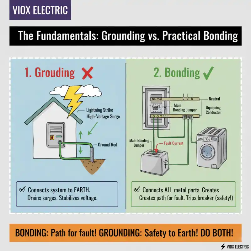
Zatímco se tyto termíny často používají zaměnitelně, uzemnění a pospojování jsou dva odlišné, ale související koncepty, které jsou nezbytné pro bezpečný elektrický systém.
- Uzemnění je akt připojení vašeho elektrického systému k samotné zemi, obvykle prostřednictvím kovové uzemňovací tyče. Primárním účelem uzemnění je stabilizovat napětí systému během normálního provozu a poskytnout cestu pro vysokonapěťové události, jako jsou údery blesku nebo přepětí v síti, aby se bezpečně rozptýlily do země.
- Pospojování je proces spojování všech nevodivých kovových částí elektrického systému dohromady. To zahrnuje kryty panelů, kovové trubky a kovové rámy spotřebičů. Cílem pospojování je vytvořit souvislou cestu s nízkou impedancí pro poruchový proud zpět ke zdroji. Tato cesta umožňuje jistič nebo pojistce detekovat poruchu a otevřít obvod, přerušit napájení a zabránit tomu, aby se kovové povrchy dostaly pod napětí a představovaly riziko úrazu elektrickým proudem.
Stručně řečeno, pospojování poskytuje cestu pro poruchový proud zpět do panelu a uzemnění poskytuje cestu pro nadproudové ochranné zařízení, aby bezpečně fungovalo a odstranilo poruchu.
Uzemňovací elektrodový systém
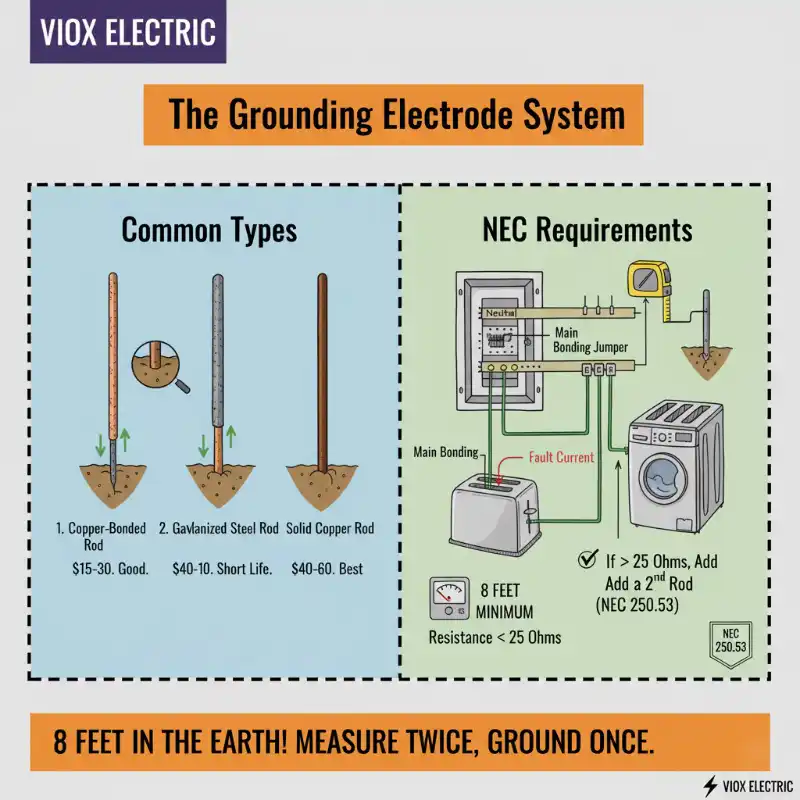
Uzemňovací elektroda je fyzická součást, která vytváří spojení mezi vaším elektrickým systémem a zemí. Je to kritický článek pro rozptýlení nebezpečných elektrických proudů.
Běžné typy elektrod
Nejběžnější uzemňovací elektrodou je kovová tyč zaražená do země. Tyto tyče jsou k dispozici z různých materiálů:
- Tyče s měděným povrchem: Ocelové jádro s měděným povlakem nabízí dobrou rovnováhu mezi pevností, vodivostí a odolností proti korozi.
- Tyče z pozinkované oceli: Jsou cenově dostupnější, ale mají kratší životnost kvůli náchylnosti ke korozi.
- Tyče z masivní mědi: Nabízejí nejlepší vodivost a nejdelší životnost, jsou prémiovou volbou, zejména pro korozivní půdní podmínky.
Požadavky NEC
Národní elektrotechnický předpis (NEC) má přísná pravidla pro uzemňovací elektrody. Podle NEC 250.53 musí mít tyčová elektroda minimálně 8 stop své délky v přímém kontaktu s půdou. Pokud je odpor jedné tyče vůči zemi naměřen na více než 25 ohmů, musí být instalována druhá tyč.
Základní požadavky NEC na uzemnění a pospojování (článek 250)
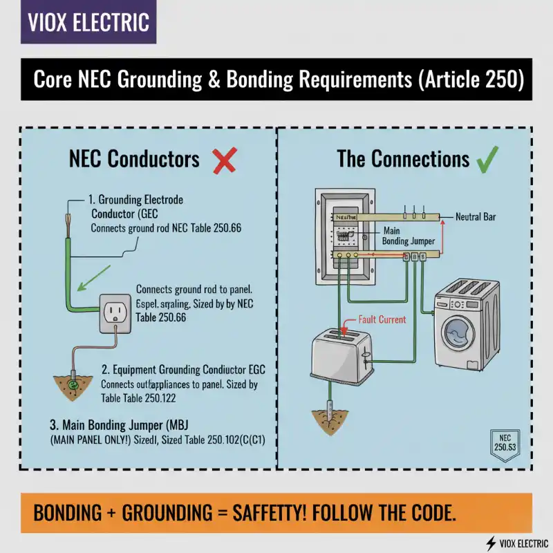
Článek 250 NEC je věnován výhradně uzemnění a pospojování a stanoví specifické vodiče a připojení, která jsou vyžadována.
- Uzemňovací elektrodový vodič (GEC): Toto je vodič, který spojuje uzemňovací elektrodu (tyč) s uzemňovací přípojnicí v hlavním elektrickém panelu. Jeho velikost je kritická a je určena velikostí vodičů vstupního vedení, jak je uvedeno v Tabulka NEC 250.66.
- Vodič ochranného uzemnění (EGC): Tento vodič, obvykle holý měděný nebo zeleně izolovaný vodič, je ten, který vede s odbočkovými obvody, aby poskytoval uzemňovací cestu pro zásuvky, svítidla a spotřebiče. Jeho účelem je poskytnout cestu s nízkou impedancí pro poruchový proud zpět do panelu. Minimální velikost EGC je založena na jmenovitém proudu nadproudového zařízení (jističe nebo pojistky), které chrání daný obvod, jak je podrobně popsáno v Tabulka NEC 250.122.
- Hlavní pospojovací můstek (MBJ): Jedná se o šroub, pásek nebo vodič, který vytváří fyzické spojení mezi neutrální přípojnicí a uzemňovací přípojnicí uvnitř hlavního servisního panelu. Jeho funkcí je spojit uzemněný vodič (neutrál) se systémem ochranného uzemnění. MBJ je dimenzován podle Tabulka NEC 250.102(C)(1).
Hlavní panel vs. podružný panel: Zásadní rozdíl
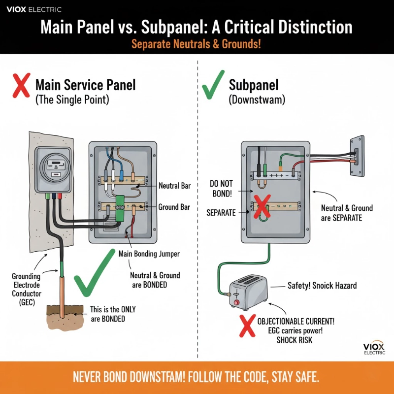
Jedno z nejdůležitějších a často nepochopených pravidel v uzemnění se týká rozdílu mezi hlavním servisním panelem a podružným panelem.
- Hlavní servisní panel: Toto je první bod odpojení pro napájení vstupující do budovy. V hlavním panelu a pouze v hlavním panelu, jsou neutrální přípojnice a uzemňovací přípojnice spojeny dohromady hlavním pospojovacím můstkem. Toto je jediný bod, kde je neutrální systém připojen k zemi.
- Podružné panely: V jakémkoli panelu napájeném z hlavního panelu (podružný panel) musí být uzemnění a neutrál odděleny. Neutrální přípojnice a uzemňovací přípojnice musí být od sebe izolovány, což znamená, že není instalován žádný hlavní pospojovací můstek. Důvodem je bezpečnost: neutrální vodič je normální zpětná cesta pro proud. Pokud jsou uzemnění a neutrál spojeny v podružném panelu, vodič ochranného uzemnění (bezpečnostní vodič) se také stane cestou pro normální zpětný proud. Toto je známé jako nežádoucí proud a vytváří vážné riziko úrazu elektrickým proudem, protože kovové části nástrojů a spotřebičů by se mohly dostat pod napětí během normálního provozu.
Průvodce instalací krok za krokem
VAROVÁNÍ: Práce uvnitř elektrického panelu je extrémně nebezpečná a může vést k vážnému zranění nebo smrti. Tato příručka je pouze pro informační účely. Důrazně doporučujeme najmout si licencovaného elektrikáře pro jakékoli práce na vašem elektrickém systému.
- Bezpečnost a příprava:
- Vypněte hlavní jistič, abyste odpojili celý panel od napětí.
- Pomocí spolehlivého testeru napětí, ověřte , že na hlavních svorkách a přípojnicích uvnitř panelu není žádné napětí.
- Používejte vhodné osobní ochranné prostředky (OOP), včetně ochranných brýlí a izolovaných rukavic.
- Shromážděte základní nástroje: tester napětí, vrtačku, kleště na dráty/odizolovací kleště a sadu nástrčných klíčů nebo klíčů.
- Instalace uzemňovací elektrody:
- Vyberte umístění v blízkosti panelu a zatlučte 8stopou uzemňovací tyč do země, dokud její horní část nebude v jedné rovině s úrovní terénu nebo pod ní.
- Zajistěte, aby byla tyč vzdálena alespoň 6 stop od jakýchkoli jiných stávajících uzemňovacích elektrod.
- Připojte uzemňovací elektrodový vodič (GEC):
- Veďte souvislý, správně dimenzovaný GEC (podle tabulky NEC 250.66) od uzemňovací elektrody k hlavnímu elektrickému panelu.
- Připevněte GEC k uzemňovací tyči pomocí uvedeného šroubovacího konektoru nebo jiného schváleného konektoru pro přímé zakopání, abyste zajistili pevné a bezpečné připojení.
- Veďte GEC do panelu a připojte jej k hlavní uzemňovací přípojnici. Tato přípojnice je ta, která je přímo spojena s kovovým krytem panelu.
- Pospojování servisního panelu:
- Vizuálně zkontrolujte, zda je nainstalován hlavní pospojovací můstek (často zelený šroub nebo kovový pásek) a bezpečně spojuje neutrální přípojnici s uzemňovací přípojnicí. Toto spojení se provádí pouze na hlavním servisním panelu.
- Testování a ověření:
- Jakmile jsou všechna připojení provedena a utažena, měl by elektrikář systém otestovat. To může zahrnovat použití multimetru ke kontrole správné kontinuity a testeru zemního odporu, aby se zajistilo, že připojení k zemi je pod 25 ohmů.
Nejčastější chyby, kterých se vyvarujte
- Spojování neutrálu a uzemnění v podružném panelu: Toto je nejnebezpečnější a nejčastější chyba. Umožňuje normální proud do uzemňovacího systému.
- Použití poddimenzovaných vodičů: Vodiče GEC a EGC musí být dimenzovány podle NEC, aby zvládly potenciální poruchové proudy.
- Nedostatečná hloubka zemnící tyče: Tyč musí mít alespoň 8 stop kontaktu se zemí, aby byla účinná.
- Použití armovací tyče jako zemnící tyče: NEC výslovně zakazuje používat výztužnou ocel (armovací tyč) jako zemnící elektrodu, protože rychle rezaví a není spolehlivým vodičem.
- Volná spojení: Všechny svorky a šrouby terminálů musí být pevně utaženy, aby byla zajištěna spolehlivá cesta s nízkým odporem.
Závěr
Správně nainstalovaný zemnící systém je základem elektrické bezpečnosti. Jedná se o komplexní systém, kde každá součást – od zemnící tyče přes propojku až po zemnící vodiče zařízení – hraje zásadní roli. Dodržování National Electrical Code není jen otázkou shody; je to kritická praxe pro ochranu osob a majetku před elektrickými riziky. Vzhledem k inherentním rizikům a technickým požadavkům se vždy poraďte s kvalifikovaným a licencovaným elektrikářem nebo si ho najměte, abyste zajistili, že elektrický systém vašeho domu je bezpečně a správně uzemněn.
