
Rychlá odpověď: Které elektrické vzorce jsou pro nízkonapěťové rozváděče nejdůležitější?
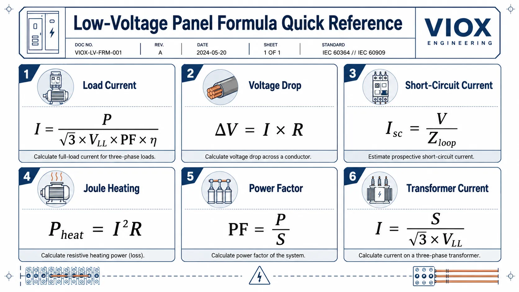
Nejužitečnější vzorce pro návrh a údržbu nízkonapěťových rozváděčů jsou proud zátěže, proud motoru, úbytek napětí, odpor vodiče, Jouleovo teplo, zkratový proud, kontrola vypínací schopnosti jističe, proud transformátoru, účiník, kompenzace kondenzátorem, nesymetrie třífázové soustavy a spotřeba energie.
V praxi při práci s rozváděči nejsou vzorce jen akademickou ozdobou. Pomáhají zodpovědět otázky z terénu, jako například:
- Jsou tento jistič (MCB), kompaktní jistič (MCCB), stykač, relé nebo kabel správně dimenzovány?
- Proč se svorkovnice přehřívá?
- Rozběhne se motor bez nadměrného úbytku napětí?
- Je vypínací schopnost jističe dostatečně vysoká pro úroveň poruchového proudu?
- Je transformátor blízko přetížení?
- Jaká kapacitní kompenzace je potřeba ke zlepšení účiníku?
- Která fáze je přetížená nebo nevyvážená?
Tato příručka je napsána jako praktická referenční příručka vzorců pro výrobce rozváděčů, údržbáře, tovární inženýry a týmy pro distribuci nízkého napětí.
Tabulka rychlé orientace
| Výpočet | Základní vzorec | K čemu slouží při rozhodování |
|---|---|---|
| Jednofázový proud | I = P / (V x PF x eta) |
Proud obvodu, velikost jističe, zatížení kabelu |
| Třífázový proud | I = P / (sqrt(3) x VLL x PF x eta) |
Přívody k motorům, hlavní přívody, rozvaděče |
| Zdánlivý výkon | S = odmocnina(3) x VLL x I |
Kapacita transformátoru, generátoru, ATS a hlavního vypínače |
| Účiník | PF = P / S |
Diagnostika jalového výkonu a dimenzování kompenzačního rozváděče |
| Kapacitní kompenzace | Qc = P x (tan phi1 - tan phi2) |
Dimenzování kompenzačního rozváděče účiníku |
| Odpor vodiče | R = ró x L / A |
Ztráty na kabelu, ztráty na přípojnici, úbytek napětí |
| Jouleovo teplo | Pteplo = I^2 x R |
Přehřáté svorky, uvolněné spoje, opotřebení kontaktů |
| Úbytek napětí | Úbytek napětí % = Delta V / V x 100 |
Dlouhá kabelová vedení, rozběh motoru, nežádoucí podpětí |
| Zkratový proud | Isc = V / Zloop |
Výběr vypínací schopnosti jističů MCB/MCCB |
| Jmenovitý proud transformátoru | I = S / (sqrt(3) x VLL) |
Dimenzování NN rozváděčů, měřicích transformátorů proudu, kabelů a jističů |
| Kontrola jističe | Vypínací schopnost >= PSCC |
Zda je vyžadována ochrana 6kA, 10kA, MCCB nebo vyšší |
| Spotřeba energie | kWh = kW x h |
Odhad provozních nákladů a profilu zatížení |
| Fázová nesymetrie | Nesymetrie v % = maximální odchylka / průměr x 100 |
Vyvažování třífázové zátěže a odstraňování poruch |
1. Proud jednofázové zátěže
Pro jednofázovou střídavou zátěž:
I = P / (V x PF x eta)Kde:
I= proud v ampérechP= činný výkon ve wattechV= napájecí napětí ve voltechúčiník= účiníketa= účinnost, pokud se jedná o motor nebo měnič
Pro čistě odporovou zátěž jsou účiník a účinnost často blízké 1, takže zjednodušený vzorec vypadá takto:
I = P / VPříklad:
2000W topné těleso v obvodu 230V odebírá přibližně:
I = 2000 / 230 = 8,7 AU topných těles, svítidel a jiných odporových zátěží tento rychlý výpočet často postačuje pro první odhad. U motorů, transformátorů, napájecích zdrojů a solenoidů záleží na účiníku a účinnosti.
2. Proud třífázové zátěže
Pro symetrickou třífázovou zátěž:
I = P / (sqrt(3) x VLL x PF x eta)Kde:
VLL= sdružené napětí (napětí mezi fázemi)odmocnina(3)= 1.732účiník= účiníketa= účinnost
Příklad:
Třífázový motor o výkonu 15 kW napájený napětím 400 V, s účiníkem 0,85 a účinností 0,90:
I = 15000 / (1,732 x 400 x 0,85 x 0,90)I ≈ 28,3 AToto je vypočtený odhad. Pro konečnou ochranu motoru a výběr stykače vždy ověřte jmenovitý proud motoru uvedený na štítku. Konstrukce motoru, třída účinnosti, provozní činitel a způsob spouštění mohou změnit skutečný provozní proud.
Pokud je výpočet součástí výběru jističe MCB nebo MCCB, použijte jej společně s proudovou zatížitelností vodičů, rozběhovým proudem, okolní teplotou a požadavky na ochranu proti zkratu. Logiku výběru jističů MCB naleznete v Průvodce výběrem jističů MCB: Jak vybrat správný miniaturní jistič.
3. Rozběhový proud motoru
Rozběhový proud motoru je často mnohem vyšší než provozní proud. Běžný odhad pro přímé spouštění motoru (DOL) je:
Istart ≈ 5 až 8 x InKde:
Istart= rozběhový proudNa adrese= jmenovitý proud motoru
Tento rozsah je pouze praktický odhad. Skutečný proud při zablokovaném rotoru závisí na konstrukci motoru, napájecím napětí, způsobu spouštění a setrvačnosti zátěže.
Proč na tom záleží:
- Jistič může během spouštění vypnout, i když je provozní proud v normě.
- Dlouhé vedení kabelu může během spouštění způsobit nadměrný úbytek napětí.
- Stykač musí být zvolen podle kategorie užití motoru, nikoliv pouze podle ustáleného provozního proudu.
- Softstartér nebo frekvenční měnič (VFD) může být vyžadován tam, kde představuje problém záběrový proud nebo mechanické rázy.
U motorových obvodů nevolte ochranu pouze na základě vzorce pro provozní proud. Zkontrolujte záběrový proud, vypínací charakteristiku, zatížení stykače, nastavení nadproudového relé a koordinaci při zkratu.
Zdánlivý výkon, činný výkon, jalový výkon a účiník.
Nízkonapěťové rozvaděče nepřenášejí pouze činný výkon. V továrnách vytvářejí motory, transformátory, svářečky a výkonová elektronika také potřebu jalového výkonu.
Klíčové vztahy jsou:
S = P / PFPF = P / SQ = odmocnina(S^2 - P^2)Kde:
P= činný výkon v kWQ= jalový výkon v kvarS= zdánlivý výkon v kVAúčiník= účiník
Pro třífázové systémy:
S = odmocnina(3) x VLL x I / 1000Příklad:
Třífázový přívod 400 V s proudem 100 A má zdánlivý výkon:
S = 1,732 x 400 x 100 / 1000S ≈ 69,3 kVAPokud je účiník 0,80:
P = S x PF = 69.3 x 0.80 = 55.4 kWTo je důvod, proč nízký účiník zvyšuje proud, i když se užitečný výkon v kW nezvyšuje. Vyšší proud znamená větší ztráty na kabelech, vyšší zatížení transformátoru, více tepla a menší rezervní kapacitu v rozváděči.
Pro základní rozlišení mezi energií a výkonem viz Rozdíl mezi kW a kWh.
5. Velikost kondenzátoru pro kompenzaci účiníku
Běžný vzorec pro kompenzaci kondenzátorem je:
Qc = P x (tan phi1 - tan phi2)Kde:
Qc= jalový výkon kondenzátoru v kvarP= činný výkon v kWphi1= úhel před korekcíphi2= úhel po korekcicos phi= účiník
Příklad:
Zátěž továrny je 100 kW. Stávající účiník je 0,75. Cílový účiník je 0,95.
Přibližné hodnoty:
tan phi1pro PF 0,75 ≈ 0,88tan phi2pro PF 0,95 ≈ 0,33
Qc = 100 x (0,88 - 0,33)Qc ≈ 55 kvarProjekt lze tedy zahájit posouzením kompenzačního rozváděče o výkonu přibližně 55 kvar a následně jej upravit na základě harmonického zkreslení, spínacích stupňů, kolísání zátěže, požadavků distributora a měření v místě instalace.
Důležitá poznámka k údržbě: neinstalujte kompenzační rozváděče bezhlavě v systémech se silným harmonickým zkreslením nebo velkým množstvím frekvenčních měničů (VFD). Může být vyžadováno použití hrazených tlumivek nebo provedení analýzy harmonických složek.
6. Odpor vodiče
Odpor vodiče je skrytá proměnná, která stojí za úbytkem napětí, ztrátami výkonu a zahříváním svorek.
R = ró x L / AKde:
R= odpor v ohmechró= měrný elektrický odpor materiáluL= délka vodičeA= průřez vodiče
Při použití ró na adrese ohm mm²/m, běžné referenční hodnoty při 20 °C jsou přibližně:
- měď:
0,01724 ohm mm²/m - hliník:
0,0282 ohm mm²/m
Toto jsou typické referenční hodnoty, nikoliv univerzální konstanty pro každý vodič. Třída materiálu, teplota, pokovení, kvalita spojů a deformační zpevnění mohou skutečnou hodnotu změnit. Pro porovnání materiálů viz Vodivost vs. rezistivita vs. % IACS.
Praktický význam:
- Delší kabel zvyšuje odpor.
- Menší průřez zvyšuje odpor.
- Hliník vyžaduje pro podobný odpor větší průřez než měď.
- Uvolněná svorka se může chovat jako nežádoucí přídavný rezistor.
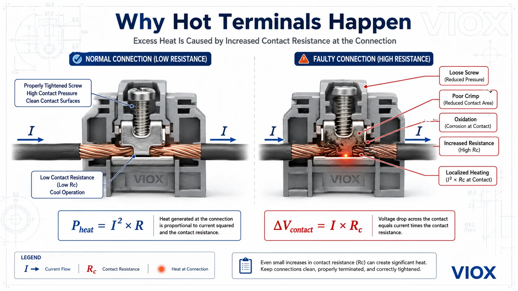
7. Jouleovo teplo: Vzorec za horkými svorkami
Teplo vznikající elektrickým odporem je:
Pteplo = I^2 x RKde:
Pheat= teplo generované ve wattechI= proud v ampérechR= odpor v ohmech
Toto je jeden z nejdůležitějších vzorců pro údržbáře. Teplo roste s druhou mocninou proudu. Pokud se proud zdvojnásobí, zahřívání se zvýší čtyřnásobně, za předpokladu, že odpor zůstane stejný.
U svorkovnic, přípojnicových spojů, kontaktů stykačů a svorek jističů není nebezpečnou proměnnou často samotný kabel, ale přechodový odpor.
Mezi běžné příčiny zvýšeného přechodového odporu patří:
- uvolněné šrouby svorek
- nesprávné krimpování
- zoxidovaný povrch vodiče
- poddimenzovaná svorka
- smíšené materiály vodičů bez náležité úpravy
- vibrace a tepelné cyklování
- poškozené kontaktní plochy
I malé zvýšení přechodového odporu může při vysokém proudu způsobit lokální zahřívání. Toto teplo urychluje oxidaci, která dále zvyšuje odpor a vytváří tak smyčku vedoucí k poruše.
Podrobnější návod k odstraňování problémů naleznete v Přehřívání svorkovnic v ovládacích panelech.
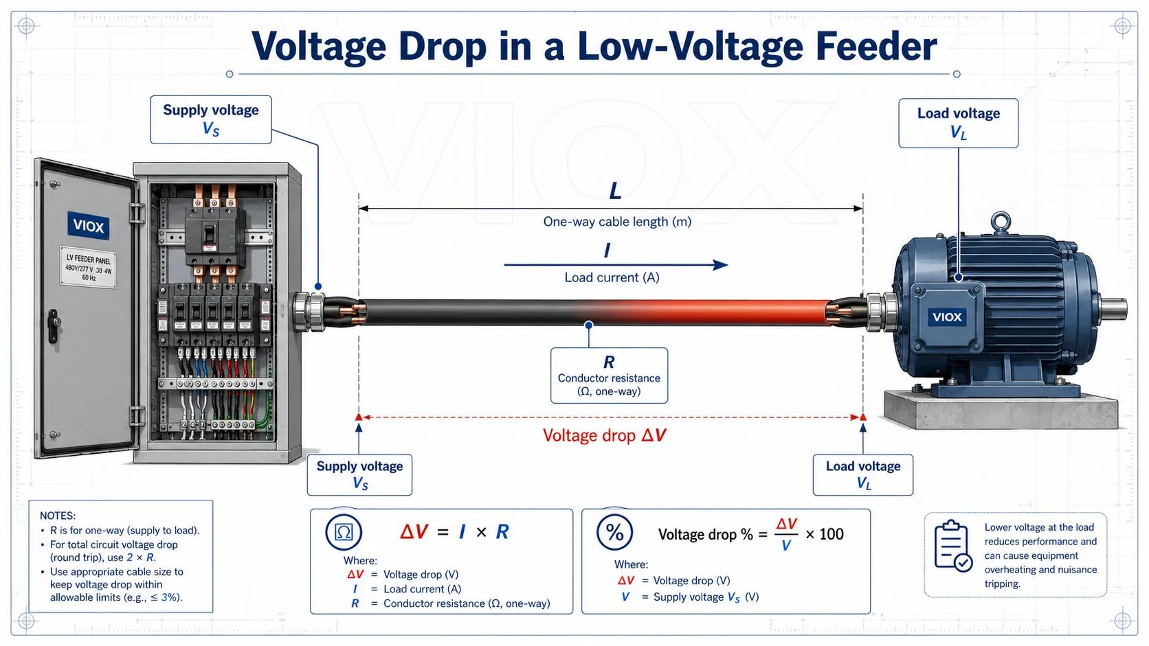
8. Výpočet úbytku napětí
Úbytek napětí je snížení napětí mezi bodem napájení a zátěží. Nadměrný úbytek napětí může způsobit:
- problémy při spouštění motoru
- bzučení stykače
- nestabilita napájení PLC
- tlumené osvětlení
- přehřívání způsobené vyšším proudem
- nežádoucí vypínání nebo alarmy podpětí
Zjednodušený stejnosměrný nebo odporový obvod:
Delta V = I x RJednofázový střídavý obvod, zjednodušeně:
Delta V ≈ 2 x L x I x R_na_metrTřífázový střídavý obvod, zjednodušeně:
Delta V ≈ odmocnina(3) x L x I x R_na_metrPro přesnější výpočet střídavého proudu zahrňte odpor, reaktanci a účiník:
Jednofázové:
Delta V = 2 x L x I x (R cos fí + X sin fí)Třífázové:
Delta V = odmocnina(3) x L x I x (R cos fí + X sin fí)Procentuální úbytek napětí:
Úbytek napětí % = Delta V / V x 100Kde:
L= délka kabelu jedním směremI= proud zátěžeR= odpor vodiče na jednotku délkyX= reaktance vodiče na jednotku délkycos phi= účiník
Úbytek napětí je obzvláště důležitý u dlouhých napáječů motorů, venkovních rozvodů, dočasného napájení, čerpacích stanic a zařízení s vysokým rozběhovým proudem.
Podrobnosti o dimenzování kabelů a úbytku napětí naleznete v IEC 60204-1 Vzorce pro dimenzování kabelů, úbytek napětí a tabulky kapacity kabelových žlabů.
9. Kontrola proudové zatížitelnosti kabelů a jmenovité hodnoty jističe
Jistič musí chránit kabel, nejen zátěž.
Běžná logika výběru podle normy IEC je:
IB <= In <= IZA:
I2 <= 1,45 x IZKde:
IB= návrhový proud zátěžeNa adrese= jmenovitý proud ochranného přístrojeIZ= proudová zatížitelnost vodiče v daných podmínkách instalaceI2= konvenční vypínací proud ochranného přístroje
Jednoduše řečeno:
- Proud zátěže by neměl překročit jmenovitý proud jističe.
- Jmenovitý proud jističe by neměl překročit proudovou zatížitelnost kabelu.
- Jistič musí vypnout dříve, než se kabel při přetížení přehřeje.
Častá chyba v praxi:
Rozvaděč je rozšířen, je nainstalován silnější jistič, ale kabel není vyměněn za silnější. Obvod má nyní papírově vyšší zatížitelnost, ale vodič již nemusí být dostatečně chráněn.
Vždy aplikujte snížení jmenovitých parametrů (derating) s ohledem na okolní teplotu, seskupení, způsob instalace, oteplení rozváděče a typ izolace vodičů v souladu s platnými místními předpisy nebo normami.
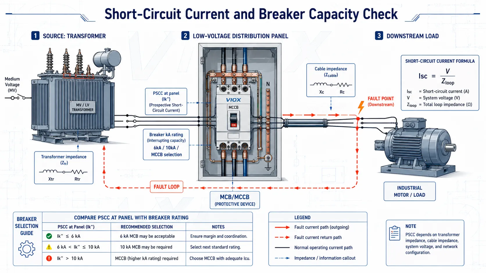
10. Zkratový proud a PSCC
Předpokládaný zkratový proud (PSCC) je poruchový proud, který by mohl protékat v daném bodě, pokud by došlo ke zkratu.
Základní princip je:
Isc = V / ZloopKde:
Isc= zkratový proudV= napětíZloop= celková impedance smyčky transformátoru, kabelu, přípojnice, zdroje a cesty poruchy
Nižší impedance znamená vyšší poruchový proud.
Proč na tom záleží:
- Jistič musí být schopen přerušit dostupný poruchový proud.
- Jistič 6kA není vhodný, pokud je PSCC v místě instalace vyšší než jeho jmenovitá zkratová vypínací schopnost.
- Rozváděče v blízkosti transformátoru mají často vyšší poruchový proud než rozváděče umístěné dále v síti.
- Dlouhá kabelová vedení snižují poruchový proud, ale zvyšují úbytek napětí.
Pro podrobný návod k výpočtu viz Jak vypočítat zkratový proud pro MCB.
11. Kontrola vypínací schopnosti jističe
Praktická kontrola spočívá v:
Vypínací schopnost jističe >= PSCC v místě instalaceU miniaturních jističů se často diskutuje o zkratové odolnosti 6 kA vs. 10 kA. U kompaktních jističů mohou relevantní hodnoty zahrnovat Icu, Ics, Icwa Icm, v závislosti na produktové normě a aplikaci.
Nezaměňujte vypínací schopnost se jmenovitým proudem.
Příklad:
C32popisuje vypínací charakteristiku a jmenovitý proud.6000nebo6kApopisuje zkratovou vypínací schopnost.10 kAznamená vyšší vypínací schopnost při zkratu, nikoliv vyšší trvalý zatěžovací proud.
Pro více podrobností viz Vypínací schopnost jističů 6kA vs 10kA a Jmenovité hodnoty jističů Icu vs Ics vs Icw vs Icm.
12. Jmenovitý proud transformátoru
Pro třífázový transformátor:
I = S / (sqrt(3) x VLL)Kde:
I= jmenovitý proudS= zdánlivý výkon transformátoru ve VAVLL= sdružené napětí (napětí mezi fázemi)
Příklad:
500 kVA transformátor s výstupním nízkým napětím 400 V:
I = 500000 / (1,732 x 400)I ≈ 722 ATo pomáhá odhadnout:
- jmenovitou velikost hlavního jističe
- proudovou zatížitelnost přípojnic
- převodový poměr měřicích transformátorů proudu (CT)
- průřez kabelů nebo přípojnicového systému
- Kapacita ATS nebo hlavního vypínače
Zkratový proud na svorkách transformátoru lze odhadnout z impedance transformátoru:
Isc ≈ IFL / (Z% / 100)Příklad:
Pokud je proud při plném zatížení transformátoru 722 A a impedance 5 %:
Isc ≈ 722 / 0,05 = 14 440 AToto je pouze odhad na svorkách transformátoru. Impedance kabelů směrem dolů snižuje poruchový proud. Konečný výběr jištění by měl využívat vypočtený PSCC v místě skutečné instalace.
13. Nesymetrie třífázové zátěže
Pro údržbu v terénu je nesymetrie fází rychlým způsobem, jak zjistit špatné rozložení zátěže.
Vzorec pro proudovou nesymetrii:
Nesymetrie % = maximální odchylka fáze od průměru / průměr x 100Příklad:
Naměřené fázové proudy:
- L1 = 82 A
- L2 = 74 A
- L3 = 69 A
Průměr:
(82 + 74 + 69) / 3 = 75 AMaximální odchylka od průměru:
82 - 75 = 7 ANesymetrie:
7 / 75 x 100 = 9,31 %Vysoká nesymetrie může indikovat:
- nerovnoměrné rozložení jednofázové zátěže
- uvolněné připojení nulového vodiče
- přetížení jedné fáze
- selhaný stupeň kondenzátorové baterie
- problém s vinutím motoru
- špatný kontakt v jedné fázi
Přípustný limit závisí na typu zařízení, místní praxi a pokynech výrobce. U motorů může i malá nesymetrie napětí způsobit neúměrně vysokou nesymetrii proudu a zahřívání, proto při hodnocení přívodů motorů používejte pokyny výrobce motoru.
14. Spotřeba energie a provozní náklady
Spotřeba energie:
kWh = kW x hProvozní náklady:
Náklady = kWh x sazba za elektřinuPříklad:
Zátěž 7,5 kW běží 10 hodin denně:
Energie = 7,5 x 10 = 75 kWh/denPokud je cena elektřiny 0,12 za kWh:
Náklady = 75 x 0,12 = 9 za denTento vzorec je jednoduchý, ale užitečný pro týmy údržby v továrnách při vyhodnocování:
- doby provozu motoru
- spotřeby energie kompresoru
- zátěže HVAC
- modernizace osvětlení
- plýtvání energií v důsledku zbytečného provozu
- návratnost investic do automatizace
15. Vzorce pro údržbu v terénu při výskytu horkých míst
Pokud má rozvaděč horkou svorku, uvažování pomocí vzorců pomáhá vyhnout se odhadům.
Úbytek napětí na kontaktu
Delta Vkontakt = I x RcKde:
Rc= přechodový odpor
Pokud dvě identické fáze vedou podobný proud, ale na jednom ze svorkových spojů dochází k vyššímu úbytku napětí, může mít tento spoj vyšší přechodový odpor.
Ohřev spoje
Pheat = I^2 x RcTo vysvětluje, proč se spoj může stát nebezpečným, i když proudové zatížení vypadá normálně. Problémem může být lokální odpor, nikoliv přetížení celého obvodu.
Praktická diagnostická logika
| Příznak | Vodítko ve vzorci | Pravděpodobný problém |
|---|---|---|
| Jedna svorka teplejší než sousední svorky | P = I^2R |
Vyšší kontaktní odpor |
| Dlouhé napájecí vedení způsobuje úbytek napětí u zátěže | Delta V = I x R |
Problém s délkou kabelu nebo průřezem vodiče |
| Jistič vypíná při rozběhu motoru | Istart ≈ 5-8 x In |
Nárazový proud nebo nesprávná vypínací charakteristika |
| Vysoký proud na hlavním přívodu při normálním výkonu v kW | S = P / PF |
Nízký účiník |
| Zpochybněna hodnota zkratové odolnosti jističe (kA) | Isc = V / Zloop |
Je nutný výpočet PSCC (předpokládaného zkratového proudu) |
| Přehřívání nulového vodiče | Nesymetrie fází a harmonické proudy | Nesymetrické nebo nelineární zátěže |
16. Časté chyby při používání elektrických vzorců
Chyba 1: Zaměňování kW za kVA
kW je činný výkon. kVA je zdánlivý výkon. Nízký účiník zvyšuje proud a zatížení transformátoru.
Chyba 2: Ignorování účinnosti při odhadu proudu motoru
Vstupní proud motoru závisí na výstupním výkonu, účinnosti, napětí a účiníku. Pro konečný výběr použijte jmenovitý proud uvedený na štítku.
Chyba 3: Kontrola jmenovitého proudu bez zohlednění vypínací schopnosti
Jistič 32 A může trvale přenášet proud 32 A, ale přesto musí mít dostatečnou vypínací schopnost při zkratu pro daný bod instalace.
Chyba 4: Výpočet úbytku napětí pouze při provozním proudu
Motory mohou mít přijatelné provozní napětí, ale nepřijatelný úbytek napětí při rozběhu.
Chyba 5: Považování proudové zatížitelnosti kabelu za pevnou hodnotu
Proudová zatížitelnost kabelu se mění v závislosti na okolní teplotě, seskupení, podmínkách uložení a způsobu instalace.
Chyba 6: Ignorování přechodového odporu
Mnoho horkých míst v rozváděči není způsobeno nesprávným proudovým zatížením. Jsou způsobena špatnými spoji, oxidací nebo poškozenými kontaktními plochami.
Chyba 7: Používání přibližných vzorců jako konečného důkazu návrhu
Rychlé vzorce jsou užitečné pro odhady a odstraňování problémů. Konečný návrh musí odpovídat příslušné normě, místním předpisům, technickému listu výrobce a specifikaci projektu.
Kontrolní seznam vzorců nízkého napětí pro výrobce rozváděčů
Před schválením návrhu rozváděče nízkého napětí zkontrolujte:
| Zkontrolujte | Vzorec nebo pravidlo |
|---|---|
| Zátěžový proud | I = P / V nebo I = P / (sqrt(3) x VLL x PF x eta) |
| Ochrana kabelů | IB <= In <= IZ |
| Úbytek napětí | Delta V % = Delta V / V x 100 |
| Jmenovitá vypínací schopnost jističe | Vypínací schopnost >= PSCC |
| Proud transformátoru | I = S / (sqrt(3) x VLL) |
| Účiník | PF = P / S |
| Kapacitní kompenzace | Qc = P x (tan phi1 - tan phi2) |
| Diagnostika přehřátých svorek | Pteplo = I^2 x R |
| Vyvážení fází | Nesymetrie v % = maximální odchylka / průměr x 100 |
| Spotřeba energie | kWh = kW x h |
ČASTO KLADENÉ DOTAZY
Jaký je nejdůležitější vzorec pro návrh nízkonapěťového rozváděče?
Nejpoužívanějším vzorcem je vzorec pro proud: pro třífázové zátěže, I = P / (sqrt(3) x VLL x PF x eta). Je to výchozí bod pro dimenzování kabelů, výběr jističů, výběr stykačů, zatížení transformátoru a kontrolu úbytku napětí.
Jaký vzorec vysvětluje přehřívání svorkovnic?
Zahřívání svorek je vysvětleno tím, že Pteplo = I^2 x R. Pokud se přechodový odpor zvýší v důsledku uvolněných šroubů, nekvalitního krimpování, oxidace nebo poškozených kontaktních ploch, může se svorka přehřát, i když se zdá, že proud zátěže je v normě.
Jak vypočítat třífázový proud?
Použijte I = P / (sqrt(3) x VLL x PF x eta). Pokud znáte pouze zdánlivý výkon, použijte I = S / (sqrt(3) x VLL).
Jak vypočítat úbytek napětí?
Pro zjednodušený odhad třífázové soustavy použijte Delta V ≈ odmocnina(3) x L x I x R_na_metr. Pro přesnější výpočty střídavého proudu zahrňte reaktanci a účiník: Delta V = odmocnina(3) x L x I x (R cos fí + X sin fí).
Jak vypočítat zkratový proud?
Základní vzorec je Isc = V / Zloop. V praxi ovlivňují předpokládaný zkratový proud v rozvaděči impedance transformátoru, délka kabelu, průřez vodiče a impedance nadřazené sítě.
Jaký je vzorec pro vypínací schopnost jističe?
Praktické pravidlo zní vypínací schopnost jističe >= předpokládaný zkratový proud. Pokud je PSCC vyšší než jmenovitá hodnota jističe, jistič není pro daný bod instalace vhodný.
Jaký je vzorec pro kompenzaci účiníku?
Použijte Qc = P x (tan phi1 - tan phi2), kde P je činný výkon, phi1 je úhel před kompenzací a phi2 je úhel po korekci.
Proč nízký účiník zvyšuje proud?
Nízký účiník zvyšuje zdánlivý výkon při stejném užitečném výkonu v kW. Protože proud v AC systému následuje zdánlivý výkon, nízký účiník zvyšuje proud, ztráty, úbytek napětí a zatížení transformátoru.
Mohou tyto vzorce nahradit software pro návrh elektroinstalace?
Ne. Jsou užitečné pro odhady, odstraňování problémů a prvotní výběr. Konečný návrh rozvaděče by měl využívat příslušné normy, místní předpisy, data výrobce, studii selektivity jištění a požadavky projektu.
Souhrn
Návrh a údržba nn rozvaděčů závisí na malé sadě správně použitých vzorců. Vzorce pro proud určují velikost zátěže. Vzorce pro úbytek napětí vysvětlují slabé napájení u zařízení. Vzorce pro zkratový proud určují, zda má jistič MCB nebo MCCB dostatečnou vypínací schopnost. Vzorce pro účiník vysvětlují, proč proud roste, i když užitečný výkon v kW nikoliv. Jouleovo teplo vysvětluje, proč se uvolněné svorky a špatné kontakty stávají horkými místy.
Pro praktický výběr jištění propojte tyto vzorce s jmenovitými hodnotami komponent: jmenovitý proud MCB/MCCB, vypínací schopnost, proudová zatížitelnost kabelů, kvalita svorek, vodivost přípojnic, zatížení stykačů a kapacita transformátoru. Právě zde se znalost vzorců mění v bezpečnější návrh rozvaděčů a rychlejší odstraňování závad v terénu.
Zdroje a související příručky VIOX
- Jak vypočítat zkratový proud pro MCB
- Průvodce vypínací schopností jističů 6kA vs 10kA MCB
- Jmenovité hodnoty jističů Icu vs Ics vs Icw vs Icm
- IEC 60204-1 Vzorce pro dimenzování kabelů, úbytek napětí a tabulky kapacity kabelových žlabů
- Přehřívání svorkovnic v ovládacích panelech
- Vodivost vs. rezistivita vs. % IACS
- Rozdíl mezi kW a kWh
