
Introduction
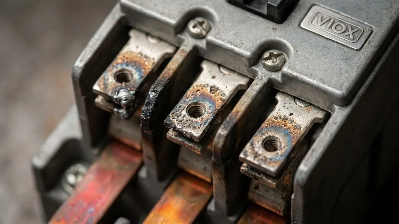
Picture this: A 50 kW solar inverter suddenly goes offline during peak production hours. The facility manager hears a loud buzzing noise from the combiner box, followed by the acrid smell of burning plastic. Upon inspection, the contactor contacts have welded shut, requiring emergency replacement and costing thousands in lost revenue. This scenario plays out daily across industrial facilities worldwide, yet most contactor failures are preventable with early diagnosis.
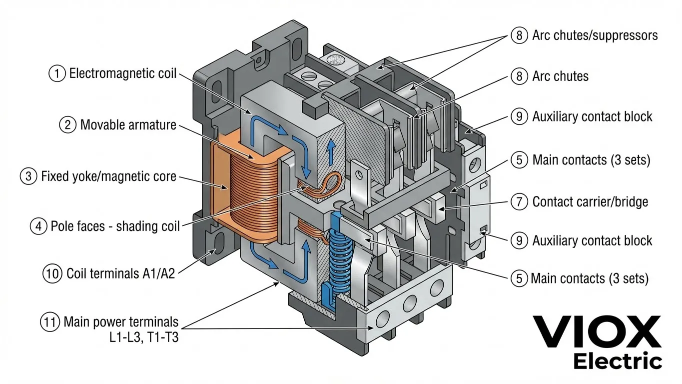
Contactors are electromagnetic switches that control high-power circuits in solar installations, motor control systems, and industrial equipment. When they fail, the consequences range from minor nuisances to catastrophic equipment damage. This comprehensive contactor troubleshooting guide covers the 10 most common contactor problems, systematic diagnostic procedures, and proven solutions to keep your systems running reliably.
Understanding Normal vs. Abnormal Contactor Operation
A properly functioning contactor operates with specific characteristics:
Normal operation includes:
- Distinct single “click” sound when energizing (coil pull-in)
- Contacts close within 20-50 milliseconds
- Steady-state operation with minimal audible hum (<40 dBA at 1 meter)
- Coil temperature rise of 40-50°C above ambient at rated load
- Contact voltage drop <100 mV at rated current
Abnormal indicators requiring investigation:
- Continuous buzzing, humming, or chattering sounds
- Delayed engagement (>100 milliseconds)
- Excessive coil heat (>80°C above ambient)
- Visible arcing or sparking at contacts
- Intermittent operation or failure to close/open
- Contact voltage drop >200 mV (indicates resistance buildup)
Understanding these baselines enables rapid identification of developing faults before they cause equipment failure.
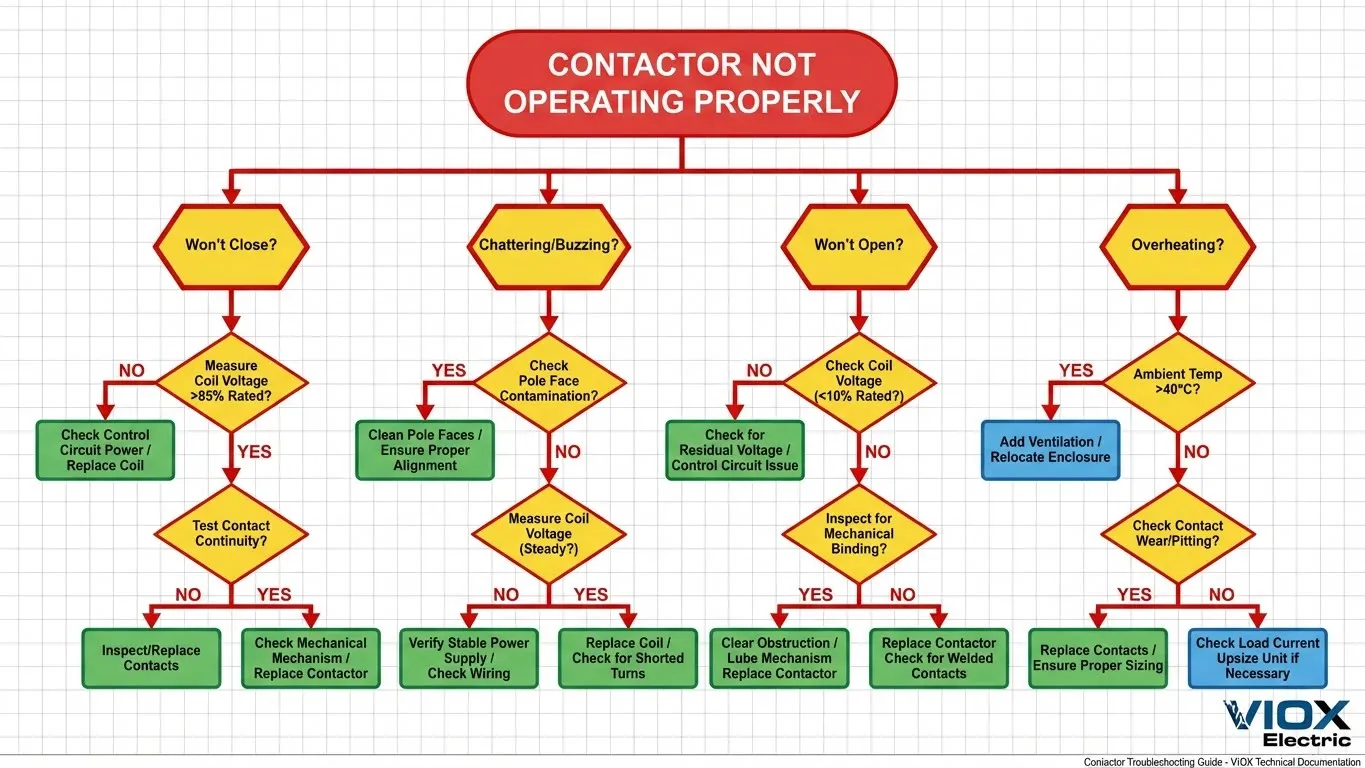
Top 10 Common Contactor Problems with Systematic Troubleshooting
Problem 1: Contactor Won’t Close (Coil Energized)
Symptoms:
- Control voltage present at coil terminals (A1/A2)
- Audible coil hum may be present
- Main contacts remain open
- Connected equipment doesn’t start
- No “click” sound when control signal applied
Root Causes:
A. Insufficient Coil Voltage
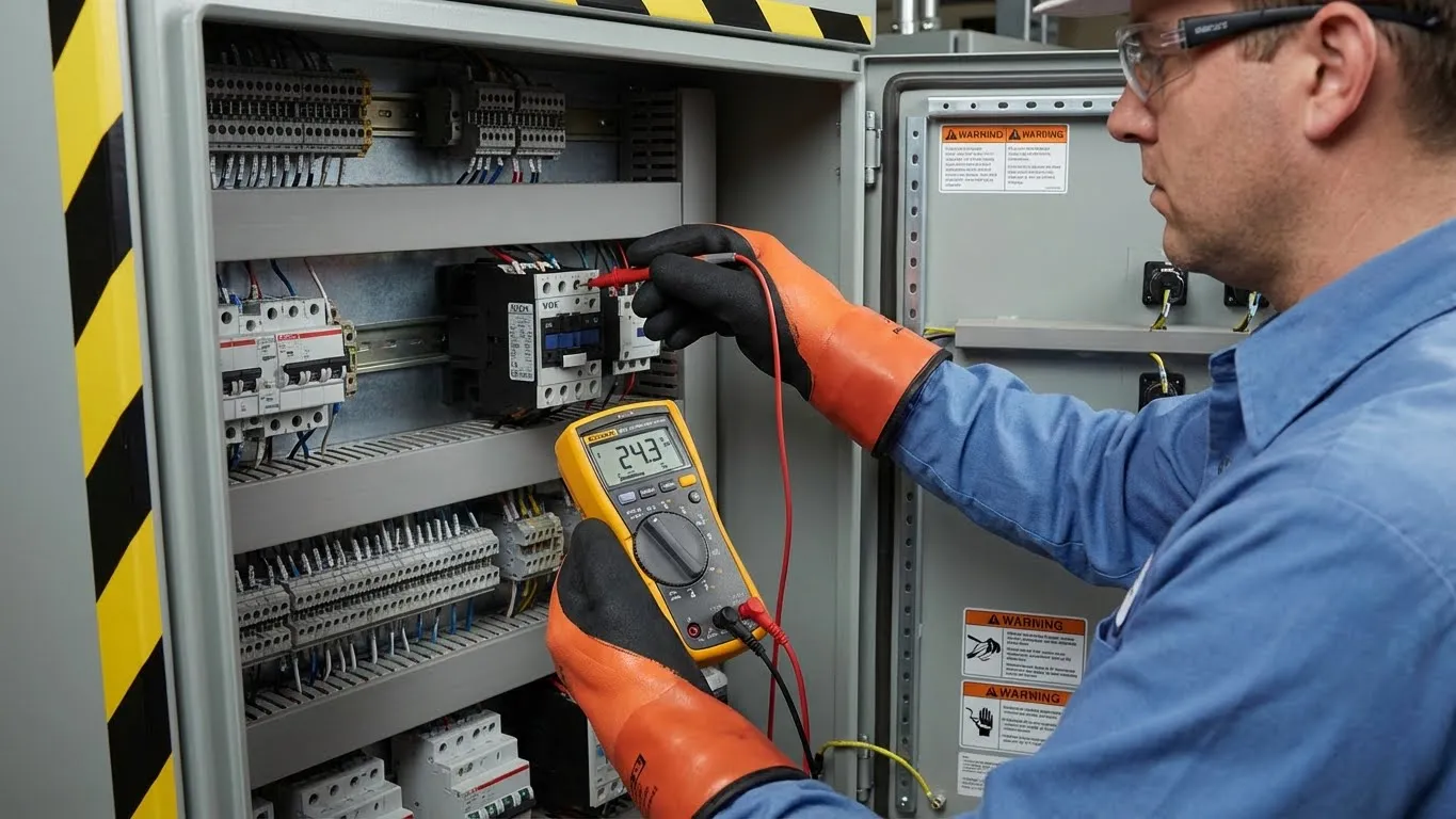
- Diagnosis: Measure voltage at coil terminals while energized (under load)
- Acceptable range: 85-110% of rated voltage (e.g., 20.4-26.4V for 24V coil)
- Solution: If voltage <85% of rated, trace control circuit for voltage drop. Check control transformer sizing, wire gauge (should be 18 AWG minimum for 24V circuits), and connection integrity at all terminals.
B. Mechanical Obstruction
- Diagnosis: De-energize system, manually inspect armature movement
- Solution: Look for debris, plastic shavings from panel fabrication, corrosion, or deformed mounting hardware preventing armature travel. Clean with electrical contact cleaner (CRC 2-26 or equivalent) and compressed air at 60-80 PSI.
C. Burned or Open Coil
- Diagnosis: De-energize and measure coil resistance with multimeter
- AC coils: Typically 100-500Ω (varies by voltage rating)
- DC coils: Typically 50-200Ω
- Open circuit (OL or ∞Ω) = burned winding
- Very low resistance (<5Ω) = shorted turns
- Solution: Replace contactor immediately. Burned coils indicate overvoltage exposure or coil-to-frame insulation failure.
D. Welded Contacts from Previous Fault
- Diagnosis: Contacts stuck closed from last operation cycle
- Solution: Replace contactor and investigate root cause (short circuit, overload, excessive inrush current) before re-energizing circuit.
Pro Tip: Always measure coil voltage under load (energized). Control voltage may appear correct with no load but drop below pickup threshold when coil draws inrush current (typically 5-10× sealed current).
Problem 2: Contactor Chattering/Buzzing
Symptoms:
- Rapid clicking or rattling noise (multiple cycles per second)
- Loud 50/60 Hz hum or buzz
- Contacts repeatedly opening/closing
- Accelerated contact wear and pitting
- May eventually fail to close completely
- Visible arcing at contact points
Root Causes:
A. Low Control Voltage
- Root Cause: Voltage drops below pull-in threshold (typically 85% of rated) but above drop-out threshold (typically 60% of rated), causing rapid cycling
- Diagnosis: Measure coil voltage under load. Chattering typically occurs at 70-85% of rated voltage
- Solution:
- Verify control transformer capacity (VA rating must exceed coil inrush + other loads)
- Check wire sizing: 18 AWG max for 24V circuits up to 50 feet
- Clean/tighten all control circuit connections
- Measure voltage drop across control switches (should be <0.5V)
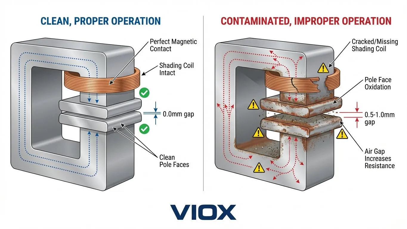
B. Contaminated Pole Faces
- Root Cause: Dirt, rust, oil, or metal filings on magnetic pole faces prevent full armature closure, increasing air gap and reducing magnetic holding force
- Diagnosis: Visual inspection of pole faces after de-energizing
- Solution: Clean pole faces using:
- Electrical contact cleaner (CRC QD Electronic Cleaner)
- 400-600 grit emery cloth for rust removal
- Ensure mating surfaces are flat and parallel
- Blow out contactor housing with compressed air
C. Broken Shading Coil (AC Contactors Only)
- Root Cause: AC contactors use copper shading rings embedded in pole faces to prevent chattering during 60 Hz zero crossings. Cracked or broken rings eliminate this function
- Diagnosis: Visual inspection—look for broken copper ring on pole face or visible cracks
- Solution: Replace contactor (shading coils are not field-serviceable). This is a manufacturing defect if new, or fatigue failure if >5 years old.
D. Wrong Coil Type or Voltage
- Root Cause: DC coil installed where AC specified, or incorrect voltage rating
- Diagnosis: Verify coil marking matches control voltage and type (AC vs. DC)
- Solution: Install correct contactor. Common mistakes: 24V DC coil on 24V AC circuit, or 110V coil on 120V circuit with high voltage drop.
Warning: Contactor chattering accelerates contact erosion by 10-20× normal wear rate. Address immediately to prevent welded contacts.
Problem 3: Contactor Won’t Open (Welded Contacts)
Symptoms:
- Control voltage removed but equipment continues running
- No audible “click” when de-energizing
- Emergency stop (E-stop) doesn’t disconnect load
- Continuity across power terminals with coil de-energized
- Potential safety hazard—equipment can’t be shut down
Root Causes:
A. Welded Contacts from Excessive Arc Energy
- Root Cause: High-energy arcs during contact interruption fused contacts together (welding temperature: >1,000°C for silver alloys)
- Diagnosis:
- De-energize control circuit completely
- Measure continuity across power terminals (L1-T1, L2-T2, L3-T3)
- Continuity present with coil de-energized = welded contacts
- Solution: Replace contactor immediately. Do not attempt to force contacts open.
- Prevention:
- Ensure contactor rated for utilization category (AC-3 for motors, AC-4 for plugging/jogging)
- Verify short-circuit rating exceeds available fault current
- Install RC snubbers for inductive loads (0.1 µF + 100Ω across coil)
- Use contactors with higher Ith rating for frequent switching
B. Weak or Broken Return Spring
- Root Cause: Spring providing opening force has fatigued or fractured after extended cycling
- Diagnosis: Visual inspection—spring should have visible tension when compressed
- Solution: Replace contactor (springs are not typically field-replaceable on modern enclosed contactors)
C. Mechanical Binding
- Root Cause: Warped frame (from overheating), misaligned components, or debris preventing armature return
- Diagnosis: Manually attempt to move armature with coil de-energized (use insulated tool)
- Solution: If movement restricted:
- Inspect for warped plastic housing (indicates thermal overload)
- Remove debris between armature and frame
- Check for damaged guide pins or bent contact carrier
- If frame warped, replace entire contactor
Problem 4: Overheating
Symptoms:
- Contactor hot to touch (>80°C/176°F surface temperature)
- Discolored plastic housing (browning or melting)
- Burnt smell (phenolic or acrid odor)
- Premature contact wear and increased resistance
- Thermal cutouts tripping in associated equipment
Root Causes:
A. Undersized Contactor for Continuous Load
- Root Cause: Continuous current exceeds rated thermal current (Ith)
- Diagnosis: Measure actual load current with clamp meter over 15-minute period
- Solution: Upsize contactor to handle 125% of measured continuous current per NEC 430.83
B. High Ambient Temperature Without Derating
- Root Cause: Panel temperature >40°C without applying derating factors
- Diagnosis: Measure panel interior temperature with thermocouple or IR thermometer
- Solution:
- Add forced ventilation (panel fans: 100-200 CFM for typical 24×36″ panel)
- Apply derating: Reduce contactor rating by 10% for every 10°C above 40°C
- Relocate contactors away from heat sources (VFDs, transformers, resistor banks)
C. Loose Terminal Connections
- Root Cause: High resistance at terminals causes I²R heating
- Diagnosis: Thermal imaging reveals hot spots at terminals (>20°C above adjacent conductors), or voltage drop measurement across connection >50 mV
- Solution:
- Tighten all power terminals to manufacturer torque specification (typically 1.2-2.5 N⋅m for M4 screws)
- Clean oxidized copper surfaces with wire brush or ScotchBrite pad
- Replace damaged or deformed terminals/lugs
- Use properly sized ring terminals (not spade terminals for high-current applications)
D. Excessive Switching Frequency
- Root Cause: Operating beyond designed duty cycle (operations per hour)
- Diagnosis: Count or log operations per hour (should not exceed 300-600/hr depending on contactor size and rating)
- Solution:
- Reduce cycle frequency through process optimization
- Select higher electrical durability contactor (AC-4 rated)
- Consider solid-state contactors or soft starters for high-frequency applications (>600 ops/hr)
Problem 5: Short Electrical Life (Premature Contact Failure)
Symptoms:
- Contacts pitted/eroded after <100,000 operations (normal life: 0.5-1 million operations for AC-3 duty)
- Loss of spring tension in contact pressure springs
- Increasing contact resistance (>100 mV voltage drop)
- Frequent nuisance tripping
Root Causes and Solutions:
- A. Exceeding Rated Utilization Category: Using AC-3 rated contactor for AC-4 application. Solution: Upgrade to AC-4 or AC-4a rated contactor.
- B. Switching Locked Rotor Current: Attempting to start motor with mechanical jam. Solution: Add current monitoring relay.
- C. Inductive Load Without Surge Suppression: High voltage spikes from collapsing magnetic fields. Solution: Install RC snubbers (0.1-0.47 µF + 100-220Ω) across coil and inductive loads.
- D. Corrosive Atmosphere: Chemical fumes attack silver contact material. Solution: Upgrade to IP65 rated enclosure or hermetically sealed contacts.
Problem 6: Auxiliary Contact Failure
Symptoms:
- Main contactor operates correctly but control circuits malfunction
- Interlocks don’t function (multiple contactors can close simultaneously)
- PLC doesn’t receive feedback signals
Diagnosis:
- Test auxiliary contact continuity with contactor de-energized
- Energize contactor and re-test (contacts should reverse state within 5-10 milliseconds)
- Measure contact resistance (should be <10 mΩ when closed)
Solution:
- Replace auxiliary contact block if modular design
- Replace entire contactor if auxiliary contacts integral to frame
Problem 7: Coil Failure
Symptoms:
- No hum or vibration when control signal applied
- Infinite resistance across coil terminals (open circuit)
- Contactor doesn’t respond to control signals
Root Causes:
- A. Overvoltage Application: Applied voltage >110% of rated coil voltage. Prevention: Verify control voltage matches coil rating ±10%.
- B. Ambient Overheating: Panel temperature >70°C. Prevention: Maintain adequate panel ventilation.
- C. Moisture/Contamination Ingress: Water infiltration. Prevention: Use IP54/IP65 enclosures.
Diagnostic Procedure:
- De-energize circuit completely (lockout/tagout)
- Disconnect coil wiring
- Measure coil resistance (should be 50-500Ω depending on voltage rating)
- Measure insulation resistance coil-to-frame using megger at 500V DC (should be >10 MΩ)
- If open circuit or low insulation resistance, replace contactor
Problem 8: Erratic Operation
Symptoms:
- Intermittent operation without clear pattern
- Works sometimes, fails other times
Troubleshooting Approach:
- A. Intermittent Control Circuit Fault: Check all control circuit connections, look for damaged wire insulation.
- B. Thermal Expansion/Contraction Effects: Connections expand when hot. Solution: Re-torque connections; use spring-loaded terminal blocks.
- C. Electromagnetic Interference (EMI): Caused by nearby VFDs. Solution: Install RC snubber, use shielded twisted-pair cable.
Problem 9: Main Contacts Stuck Open
Symptoms:
- Coil energizes (audible hum/click present) but contacts don’t close
- No continuity L1-T1, L2-T2, L3-T3 with coil energized
Diagnosis:
- Verify coil truly energized (measure voltage at 85-110% rated)
- Check for magnetic holding force
- Mechanical inspection for debris, contact carrier damage, or worn springs
Solution: Replace contactor. Worn contact springs or mechanical wear are not field-serviceable.
Problem 10: Nuisance Tripping in Control Circuit
Symptoms:
- Contactor unexpectedly drops out during operation
- Thermal overload relay trips without clear overload condition
Investigation:
- A. Voltage Sag During Motor Starting: Heavy motor inrush loads cause voltage dips. Solution: Derive control power from separate circuit.
- B. Loose Connections in Control Circuit: Inspect and tighten all terminations.
- C. Failed Overload Relay: Test overload relay; replace if tripping at <90% of setpoint.
Comprehensive Troubleshooting Quick Reference Table
| Problem | Symptoms | Most Common Cause | Quick Test | Solution | Prevention |
|---|---|---|---|---|---|
| Won’t Close | No click, coil hums, contacts open | Low coil voltage | Measure voltage at A1/A2 under load | Verify 85-110% rated voltage present | Use properly sized control transformer |
| Chattering | Rapid clicking, buzzing sound | Contaminated pole faces or low voltage | Visual inspection of pole faces; voltage check | Clean pole faces with contact cleaner; verify voltage | Monthly inspection, maintain <40°C ambient |
| Won’t Open | Continues running after de-energize | Welded contacts | Continuity test L1-T1 with coil off | Replace contactor immediately | Proper sizing for application, surge suppression |
| Overheating | >80°C surface temp, discoloration | Loose connections or undersized unit | Thermal imaging or voltage drop test | Tighten connections; upsize contactor | Annual thermography, proper torque specs |
| Short Life | Contacts worn <100k ops | Wrong utilization category | Compare load type to AC-3/AC-4 rating | Upgrade to appropriate rating | Match utilization category to application |
| Aux Contact Fail | Interlocks fail, no PLC feedback | Worn auxiliary contacts | Continuity test NO/NC contacts | Replace aux contact block | Add RC snubbers on inductive aux loads |
| Coil Failure | No response, open circuit | Overvoltage or moisture | Measure coil resistance (50-500Ω) | Replace contactor; investigate voltage | Use correct IP rating, voltage monitoring |
| Erratic Operation | Intermittent failures | Loose control wiring | Monitor voltage over time; check connections | Tighten all terminals to spec | Spring-loaded terminals, EMI shielding |
| Contacts Stuck Open | Coil works but no contact closure | Worn springs or debris | Manual armature movement test | Replace contactor | Regular cleaning, debris-free environment |
| Nuisance Tripping | Unexpected shutdowns | Voltage sag or failed overload | Monitor voltage during start; test overload | Separate control power source | Dedicated control circuits, proper OL sizing |
Preventive Maintenance Checklist
Monthly Inspections (Operating Contactors):
- Visual inspection for discoloration, cracks, or physical damage
- Listen for abnormal noises during operation (buzzing, chattering)
- Verify indicator lights and auxiliary contacts function correctly
- Check for loose mounting hardware or vibration damage
- Infrared temperature check (surface should be <60°C at rated load)
Quarterly Maintenance (Recommended):
- De-energize and clean pole faces with contact cleaner
- Inspect main contacts for pitting or erosion (replace if pits >1mm depth)
- Check contact alignment and travel distance
- Verify coil resistance within ±10% of nameplate specification
- Test auxiliary contacts for proper operation and low resistance
- Tighten all power and control terminals to specification torque
- Clean interior of enclosure with compressed air
Annual Maintenance (Critical):
- Full contactor disassembly and cleaning (if serviceable design)
- Replace contactors showing signs of thermal damage or heavy contact wear
- Thermographic inspection of all terminals and connections
- Insulation resistance testing coil-to-frame (>10 MΩ required)
- Verify control voltage stability under load conditions
- Review and log electrical life remaining (based on operations counter if available)
- Update maintenance records with findings
Replacement Intervals by Application:
- Light duty (<100 ops/day): 7-10 years
- Medium duty (100-300 ops/day): 4-6 years
- Heavy duty (>300 ops/day): 2-3 years
- Replace immediately if: welded contacts, cracked housing, coil failure, or >50% contact material loss
Frequently Asked Questions
Q: Why does my contactor buzz loudly at startup but quiet down after a few seconds?
A: This is typically caused by high inrush current when the coil first energizes, creating stronger magnetic vibration until the armature fully seats. However, if buzzing persists beyond 1-2 seconds, check for contaminated pole faces or insufficient coil voltage. Normal operation should produce only a single “thunk” followed by near-silent operation. Persistent buzzing accelerates wear and indicates a problem requiring correction.
Q: Can I clean pitted contacts instead of replacing the entire contactor?
A: Minor surface oxidation and light pitting (<0.5mm depth) can be cleaned with 400-600 grit emery cloth and contact cleaner. However, deep pitting (>1mm), contact material loss >30%, or any evidence of welding requires contactor replacement. Never file contacts aggressively—this removes the silver-cadmium oxide layer that provides arc resistance. For critical applications, replacing worn contacts is more cost-effective than risking premature failure.
Q: How often should contactors be replaced in solar installations?
A: Solar combiner box contactors typically operate 2-4 times daily (sunrise/sunset) plus occasional maintenance switching. At this duty cycle, expect 10-15 year lifespan. However, replace immediately if you observe: welded contacts, thermal damage, coil failure, or operation count exceeds 500,000 cycles. UV exposure and temperature cycling can accelerate housing degradation—inspect annually.
Q: What causes welded contacts, and how can I prevent it?
A: Welded contacts result from excessive arc energy during interruption, typically caused by: (1) interrupting short-circuit current exceeding contactor rating, (2) switching highly inductive loads without suppression, (3) rapid jogging/plugging operations, or (4) using AC-3 rated contactor for AC-4 application. Prevention: ensure contactor rated for 125% of maximum load current, install RC snubbers on inductive circuits, and select appropriate utilization category for your motor control application.
Q: Is contactor chattering dangerous, or just annoying?
A: Chattering is extremely dangerous and requires immediate correction. Rapid contact opening/closing creates repetitive arcing that: (1) accelerates contact erosion by 10-20× normal rate, (2) generates excessive heat potentially melting plastic housing, (3) creates fire hazard from sustained arcing, (4) causes voltage fluctuations damaging sensitive electronics, and (5) mechanically stresses components leading to sudden failure. Never ignore chattering—it always indicates an underlying fault requiring diagnosis.
Q: Can low voltage damage contactors even if they still operate?
A: Yes. Operating contactors at <85% rated coil voltage causes several problems: (1) incomplete armature travel results in higher contact resistance and heating, (2) reduced magnetic holding force allows contacts to bounce during vibration, creating arcing, (3) coil draws higher current attempting to maintain magnetization, causing coil overheating, and (4) chattering mechanically stresses components. Always verify coil voltage is 85-110% of rating. Chronic low voltage operation can reduce contactor lifespan by 50% or more.
Q: When should I repair versus replace a faulty contactor?
A: Replace when: welded contacts, cracked/melted housing, coil resistance out of specification, contact material loss >30%, broken shading coils, or age >10 years. Repair (cleaning) when: light surface oxidation on contacts (<0.5mm pitting), contaminated pole faces, loose terminals (re-torque), or dirty auxiliary contacts. Modern enclosed contactors have limited field serviceability—replacement is typically more economical than attempting extensive repairs. For critical safety applications, always replace rather than repair.
Conclusion
Systematic contactor troubleshooting prevents costly downtime and equipment damage. The key to effective diagnosis is understanding normal operating parameters, recognizing early warning signs, and applying methodical testing procedures. Most contactor failures are preventable through proper sizing, regular maintenance, and operating within specified ratings.
When troubleshooting contactors, always prioritize safety: de-energize circuits before inspection, use appropriate PPE, and follow lockout/tagout procedures. For complex industrial systems, consider consulting with motor control specialists to ensure proper application and sizing.
VIOX Electric manufactures industrial-grade contactors designed for reliability in demanding applications including solar installations, motor control, and industrial automation. Our technical support team provides application engineering assistance for proper contactor selection and troubleshooting support.
