")
The Silent Killer: Back EMF and Its Consequences
Every time you de-energize an industrial contactor, you’re triggering a phenomenon that can destroy your equipment in seconds. The culprit? Back electromotive force (EMF) – a voltage spike that occurs when current through an inductive load (like a relay or contactor coil) is suddenly interrupted.
Here’s the problem: A 24V DC coil can generate a reverse voltage spike of -400V or higher – up to 20 times the rated voltage. Without proper suppression, this spike will:
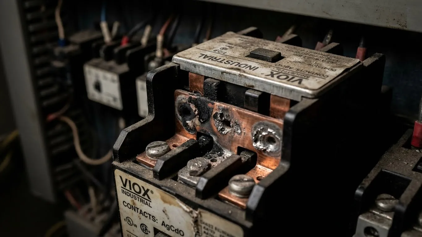
- Arc across relay contacts, causing pitting, welding, and premature failure
- Destroy PLC transistor outputs by exceeding their voltage ratings (typically 30-50V)
- Generate electromagnetic interference (EMI) that disrupts nearby control circuits
But here’s the paradox most engineers miss: The better you protect your PLC, the faster you kill your contactor contacts.
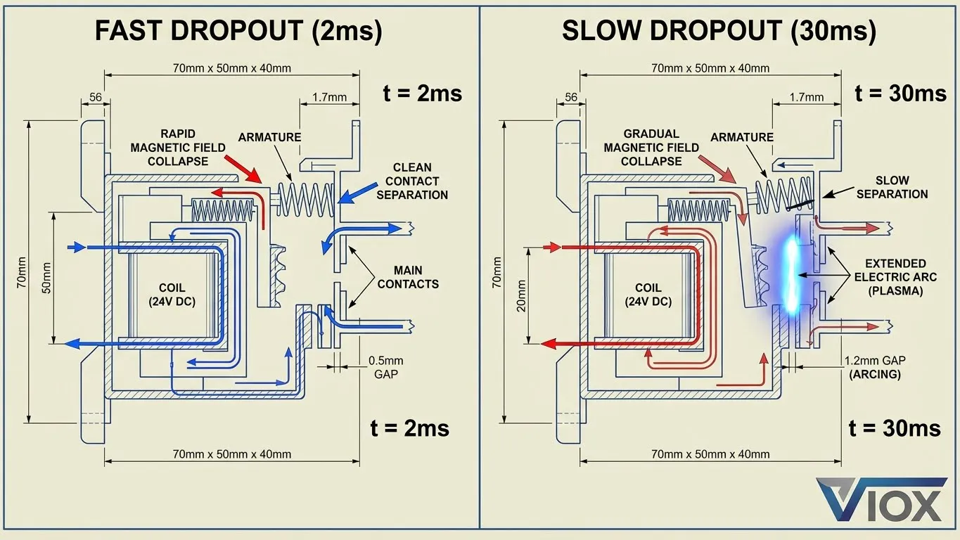
Standard flyback diodes clamp voltage beautifully (0.7V) but create a new problem – they trap energy in the coil, slowing dropout time from 2ms to 30-50ms. During this extended period, your contacts are opening slowly through a sustained arc, literally burning themselves to death.
The engineering challenge: You must balance three competing factors – voltage clamping, dropout speed, and cost. Choose wrong, and you’re either replacing PLCs or contactors every few months.
Technique 1: Standard Freewheeling Diode (The PLC Protector That Kills Contacts)
How It Works
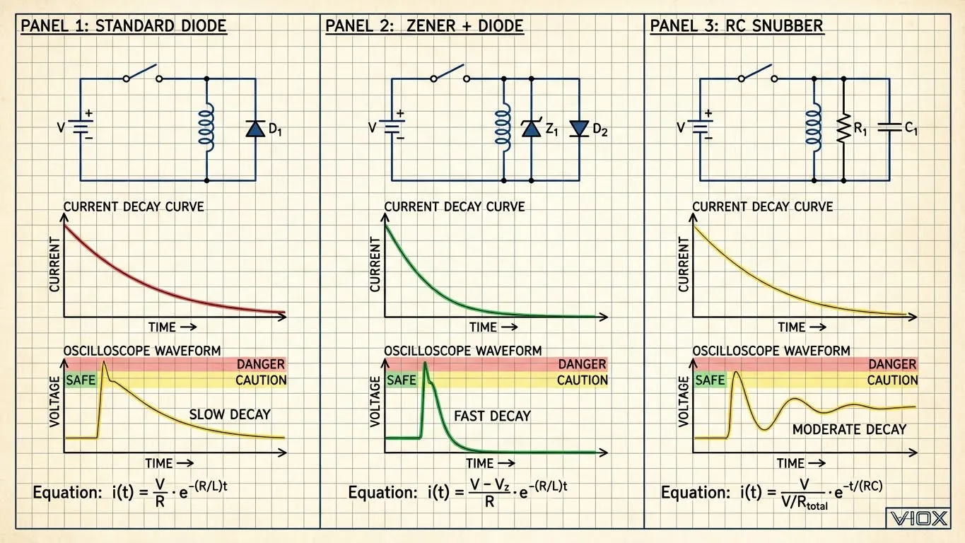
The most common suppression method places a general-purpose diode (typically 1N4007) in parallel with the coil, cathode to positive. When the coil is energized, the diode is reverse-biased and does nothing. When power is cut, the collapsing magnetic field forward-biases the diode, creating a closed loop for current to circulate.
Technical principle: The stored energy (½LI²) dissipates slowly through the coil’s DC resistance and the diode’s 0.7V forward drop. Current decay follows an exponential curve: I(t) = I₀ × e^(-Rt/L).
Advantages
- Lowest cost: $0.10-0.30 per diode
- Best voltage clamping: Limits reverse voltage to 0.7V above supply
- Maximum PLC protection: Keeps voltage well below transistor breakdown limits
- Simple implementation: No calculations required
The Critical Flaw: Delayed Dropout
Here’s what your supplier won’t tell you: That protective diode is destroying your contactor contacts.
For a typical 24V contactor coil (inductance 100mH, resistance 230Ω, current 104mA), the time constant τ = L/R = 0.43 seconds. The current doesn’t drop instantly – it takes approximately 5τ (2.15 seconds) to decay to near zero.
Real-world impact: A DG85A relay with no suppression opens in <2ms. Add a standard diode, and dropout time increases to 9-10ms – a 5x slowdown.
Why this matters:
- Contact gap opens slowly (reduced magnetic holding force)
- Arc duration increases from 1-2ms to 8-10ms
- Arc energy = ∫V×I×dt increases exponentially
- Contact material (AgCdO, AgNi, AgSnO₂) erodes faster
- Contact life drops by 50-70%
For DC motor applications, the problem compounds: The spinning motor acts as a generator during deceleration, adding back-EMF to the arc. Combined with slow contact opening, you get sustained arcing that can weld contacts shut.
When to Use
- Small signal relays (5V, <1A) controlling non-critical loads
- Applications where contact life isn’t critical
- Low-frequency switching (<100 cycles/hour)
- Never use for contactors controlling motors, solar strings, or high-cycle applications
Technique 2: Diode + Zener Combination (VIOX Recommended Solution)
How It Works
This configuration places a Zener diode (typically 36V for 24V coils) in series with a standard diode (1N4006), connected in parallel with the coil. During normal operation, both diodes block. At turn-off, the back-EMF reverse-biases the Zener, which conducts once the voltage exceeds VZ + 0.7V.
Energy dissipation: Power = (VZ + VF) × I. A 36V Zener dissipates energy 50x faster than a 0.7V standard diode, dramatically reducing dropout time.
Advantages
Fast dropout: Release time approaches the contactor’s natural mechanical speed (3-5ms for typical AC contactors). For a 24V/290mA coil with 36V Zener suppression, dropout time reduces from 33ms (diode-only) to approximately 5-7ms.
Contact protection: Shortened arc duration = exponentially less contact erosion. Field tests show contact life improvement of 3-5x compared to standard diode suppression.
Controlled voltage: The voltage across the switching device is predictable: V = VSupply + VZener + VDiode (e.g., 24V + 36V + 0.7V = 60.7V)
Optimal energy balance: Fast enough to protect contacts, but not so fast that voltage spikes exceed PLC ratings.
Disadvantages
Higher clamping voltage: The 60V spike (in above example) must be below your PLC output’s VCEO rating. Most industrial PLCs handle 60-80V, but verify specifications.
Component cost: $0.80-1.50 per network vs. $0.10 for standard diode
Heat dissipation: Zener must be rated for peak power: P = VZ × ICoil. For 24V/0.29A coil with 36V Zener: P = 36V × 0.29A = 10.4W instantaneous. Use ≥5W Zener with proper heatsinking.
Design Guidelines
For 12V coils: Use 24V Zener (clamping voltage: 12V + 24V + 0.7V = 36.7V)
For 24V coils: Use 36V Zener (clamping voltage: 24V + 36V + 0.7V = 60.7V)
For 48V coils: Use 56V Zener (clamping voltage: 48V + 56V + 0.7V = 104.7V)
Critical rule: Ensure VSupply + VZener + VF < 80% of your PLC output’s maximum rating.
When to Use
- High-frequency switching contactors (>100 cycles/hour)
- Motor starters and reversing contactors
- Solar DC contactors in combiner boxes
- Any application where contact life is critical
- VIOX recommendation: All DC contactors rated ≥16A
Technique 3: RC Snubber (The AC Solution)
How It Works
An RC snubber consists of a resistor and capacitor in series, connected across the coil or contacts. The capacitor absorbs the voltage spike (limits dV/dt), while the resistor dissipates the stored energy as heat.
Design calculation:
- R = RL (coil resistance)
- C = L/RL² (where L is coil inductance)
Example: For a 230Ω, 100mH coil: C = 0.1H / (230Ω)² = 1.89µF (use 2.2µF)
Advantages
AC/DC universal: Unlike diodes, works with both AC and DC coils. Essential for AC contactors where polarity reverses 50/60 times per second.
EMI suppression: The capacitor naturally filters high-frequency noise generated during switching.
No polarity concerns: Can be installed without regard to circuit polarity.
Contact arc reduction: Capacitor slows voltage rise rate (dV/dt), reducing ionization of air gap.
Disadvantages
Complex sizing: Requires knowing coil inductance and resistance. Wrong values = ineffective suppression or continuous power dissipation.
Leakage current: The capacitor charges/discharges continuously in AC circuits. High-sensitivity relays may not release fully.
Component cost: $1-3 for rated capacitor and resistor
Power dissipation: Resistor must handle: P = C × V² × f (where f = switching frequency). For 2.2µF, 250V AC, 60Hz: P ≈ 2W minimum rating required.
Voltage rating critical: Capacitor must be rated ≥2x supply voltage (use 630V DC cap for 230V AC coils).
When to Use
- AC contactors exclusively (115V, 230V, 400V coils)
- Installations with strict EMI requirements
- Applications where diode polarity creates confusion
- Three-phase contactors controlling motors
Never use: As sole suppression for DC coils (inefficient compared to Zener+diode)
Suppression Technique Comparison Matrix
| Parameter | Standard Diode | Diode + Zener | RC Snubber |
|---|---|---|---|
| Cost per Unit | $0.10-0.30 | $0.80-1.50 | $1.00-3.00 |
| Clamping Voltage | 0.7V (best) | VZ + 0.7V (30-60V) | Moderate |
| Dropout Speed | Very slow (30-50ms) | Fast (3-7ms) | Moderate (10-20ms) |
| Contact Life Impact | ❌ Reduced 50-70% | ✅ Optimal | ⚠️ Moderate |
| PLC Protection | ✅ Excellent | ✅ Good (verify VCEO) | ✅ Good |
| AC Coil Compatible | ❌ No | ❌ No | ✅ Yes |
| DC Coil Compatible | ✅ Yes | ✅ Yes | ⚠️ Yes (but inefficient) |
| EMI Suppression | ❌ None | ❌ Minimal | ✅ Excellent |
| Installation Complexity | Simple | Simple | Complex (requires calculation) |
| Heat Dissipation | Minimal | Moderate (Zener) | Moderate (Resistor) |
| Best Application | Small signal relays | DC contactors ≥16A | AC contactors |
| Worst Application | Motor contactors | Very low-voltage PLC outputs | DC coils |
VIOX Engineering Recommendation:
- For DC contactors: Diode + Zener (36V for 24V coils)
- For AC contactors: RC Snubber (calculated values)
- For small DC relays: Standard diode acceptable
- Never use standard diode alone on contactors >10A or cycle rates >100/hour
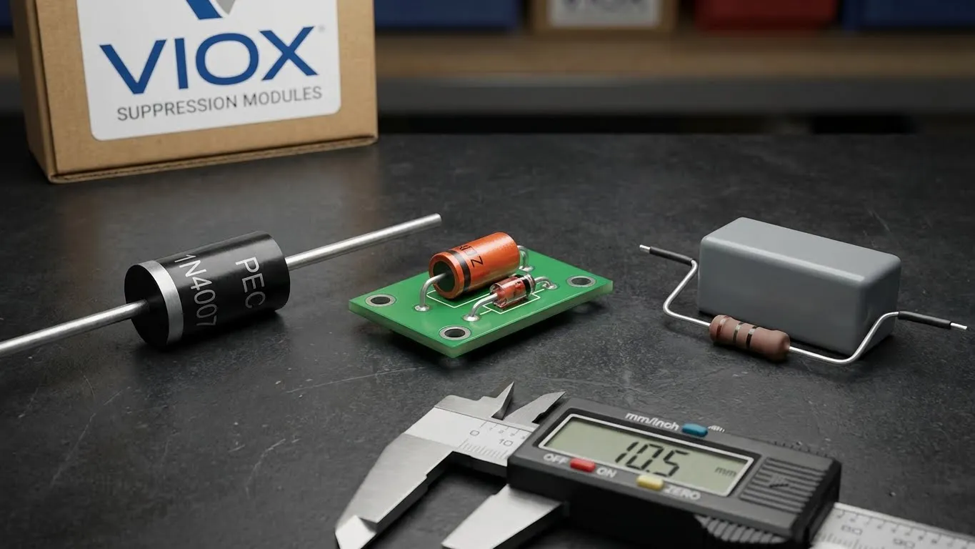
VIOX Solution: Pre-Engineered Suppression Modules
Tired of calculating RC values? Worried about selecting the wrong Zener voltage? VIOX eliminates the guesswork.
Why VIOX Plug-In Surge Suppressor Modules
Matched to coil specifications: Every VIOX contactor model has a corresponding suppression module optimized for its inductance, resistance, and voltage rating.
Proven in the field: Tested across 500,000+ switching cycles in solar DC applications, motor control, and HVAC systems.
Installation in seconds: DIN-rail mount with screw terminals. No math, no mistakes.
Component ratings: Industrial-grade Zener diodes (5W), fast-recovery rectifiers (3A), rated for -40°C to +85°C operation.
Product Range
- VX-SUP-12DC: 12V DC coils (24V Zener, 60.7V max clamp)
- VX-SUP-24DC: 24V DC coils (36V Zener, 60.7V max clamp) – most common
- VX-SUP-48DC: 48V DC coils (56V Zener, 104.7V max clamp)
- VX-SUP-230AC: 115-230V AC coils (RC network, 2.2µF/400V)
- VX-SUP-400AC: 400-480V AC coils (RC network, 1µF/630V)
Real-World Results
Solar installer case study: 50kW rooftop installation in Arizona with 12 DC contactors switching daily. Original configuration used standard flyback diodes.
- Before: Average contact replacement every 8 months (excessive pitting)
- After (VIOX Zener modules): No contact failures in 36 months, 4.5x life extension
Cost analysis: $18/module × 12 = $216 investment vs. $450/replacement × 4 avoided failures = $1,584 saved
Engineering Support
VIOX provides:
- Free suppression module with contactor orders >50 units
- Technical hotline for custom applications
- Oscilloscope verification reports for critical installations
- Maintenance guidelines for extended contact life
Don’t sacrifice contact life to protect your PLC. Get both right with VIOX.
Frequently Asked Questions
Q: Can I use a standard diode on a 100A DC contactor?
No. At 100A, the contact arc energy during delayed dropout will cause catastrophic welding within weeks. Always use Zener+diode suppression for contactors >10A. The slightly higher voltage (60V vs. 0.7V) is irrelevant compared to the cost of replacing welded contactors.
Q: What happens if I reverse the diode polarity?
Catastrophic failure. A reversed diode creates a dead short across your power supply the moment you energize the coil. The diode will explode (literally – silicon fragments), potentially taking your PLC output and power supply with it. Always verify: cathode (stripe) to positive.
Q: How do I calculate the Zener voltage for a custom coil voltage?
Use this formula: VZener = 1.5 × VCoil. For 36V coil: 1.5 × 36V = 54V Zener. This provides adequate voltage margin while keeping total clamp voltage (36V + 54V + 0.7V = 90.7V) below most industrial limits. Verify against your PLC output’s absolute maximum voltage rating.
Q: Can I use an MOV instead of a Zener diode?
Yes, but with caveats. Metal Oxide Varistors (MOVs) work for AC coils and are cheaper than RC snubbers. However, their clamping voltage is higher (typically 150-200V for a 230V AC coil) and they degrade over time with repeated surges. For DC coils, Zener+diode is superior due to tighter voltage control.
Q: My PLC output is rated for only 30V. Can I still use Zener suppression?
Not with a standard 36V Zener. You need a lower-voltage Zener (18V for 24V coils) which reduces clamp voltage to 24V + 18V + 0.7V = 42.7V. However, this slows dropout time somewhat. Alternatively, use an external relay buffer between PLC and contactor coil.
Q: Do safety contactors need different suppression?
Safety contactors with force-guided contacts are especially vulnerable to contact welding because weld detection relies on mechanical linkage integrity. Always use Zener+diode suppression on safety contactors – the fast dropout is critical for functional safety certification (ISO 13849-1).
Q: How do I test if my suppression is working?
Use an oscilloscope with 100MHz bandwidth and differential probe rated ≥400V. Measure across the coil during turn-off. You should see:
- Standard diode: Flat clamp at 0.7V, long decay (30-50ms)
- Zener+diode: Sharp spike to ~60V, fast decay (5-7ms)
- RC snubber: Damped oscillation, moderate decay (10-20ms)
If you see voltage spikes >200V, your suppression has failed or is improperly sized. Refer to contactor troubleshooting guide for diagnostic procedures.
Ready to extend your contactor life 3-5x? Contact VIOX technical sales for suppression module recommendations matched to your specific application. Our engineering team provides free circuit review and oscilloscope verification for orders >$5,000.
