
The rise of bifacial photovoltaic (PV) technology has revolutionized the solar industry, offering energy yield increases of up to 30% by capturing reflected light on the rear side of the module. However, this “bonus” energy comes with a critical engineering challenge: current gain. For electrical engineers and system designers, the variable nature of rear-side irradiance means that standard overcurrent protection sizing rules often fall short.
If you size fuses based solely on the front-side Standard Test Conditions (STC) rating, you risk nuisance tripping, equipment fatigue, and potential fire hazards during peak albedo events. As a leading manufacturer of electrical protection equipment, VIOX Electric understands that properly sizing fuses for bifacial arrays requires a nuanced understanding of both the National Electrical Code (NEC) and the physics of reflected irradiance.
The Physics of Bifacial Current Gain
Unlike traditional monofacial modules, bifacial panels feature a transparent backsheet or dual-glass design that allows light to reach the solar cells from the back. The rear side contributes to the total power output, but more importantly for circuit protection, it contributes directly to the Short Circuit Current ($I_{sc}$).
The amount of extra current generated depends heavily on the albedo (reflectivity) of the surface beneath the panels and the installation height. A panel over white commercial roofing (high albedo) will generate significantly more current than one over asphalt or grass.
Bifaciality Coefficient and Gain Factor
To size protection correctly, we must quantify this gain.
- Bifaciality Coefficient: The ratio of the rear-side efficiency to the front-side efficiency (typically 70-80% for modern PERC or TOPCon cells).
- Bifacial Gain Factor (BGF): The actual percentage increase in current during operation. While manufacturers may list a “reference” gain, real-world BGF typically ranges from 10% to 15%, with spikes up to 25-30% in optimized conditions (e.g., snow or white membranes).
Engineers cannot simply ignore this extra current. The fuse must be able to handle the Total Combined $I_{sc}$ without deteriorating, while still protecting the wire and module from faults.
NEC 690.8 and the 1.56 Rule: Adapted for Bifacial
The National Electrical Code (NEC) provides the framework for sizing PV circuits, but bifacial modules add a layer of complexity to Article 690.8.
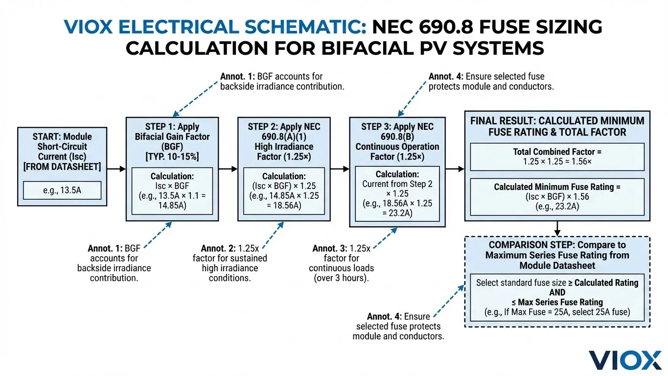
Standard sizing follows the “1.56 Rule”:
$$I_{fuse} \ge I_{sc} \times 1.25 \text{ (Irradiance Factor)} \times 1.25 \text{ (Continuous Duty Factor)}$$
For detailed guidance on standard sizing, refer to our PV Fuse Disconnect Sizing Guide (NEC 1.56 Rule).
However, for bifacial modules, $I_{sc}$ is not a static number. NEC 690.8(A)(2) allows for calculation based on the “highest 3-hour current average,” but a more common and safer engineering practice is to adjust the base $I_{sc}$ before applying safety factors.
The Adjusted Formula
To ensure compliance and safety, use the adjusted $I_{sc}$:
$$I_{sc, adjusted} = I_{sc, front} \times (1 + \text{Bifacial Gain})$$
Then apply the standard protection factors:
$$\text{Minimum Fuse Rating} = I_{sc, adjusted} \times 1.56$$
Table 1: Bifacial vs. Monofacial Current Calculation Comparison
| Parameter | Monofacial Module | Bifacial Module (15% Gain) |
|---|---|---|
| Rated $I_{sc}$ (Front) | 13.0 A | 13.0 A |
| Rear Side Gain | 0 A | +1.95 A (13.0 × 0.15) |
| Effective $I_{sc}$ | 13.0 A | 14.95 A |
| NEC Multiplier | 1.56 | 1.56 |
| Calculated Min. Fuse | 20.28 A | 23.32 A |
| Standard Fuse Size | 20A or 25A | 25A or 30A |
Note how the bifacial gain pushes the requirement to the next standard fuse size.
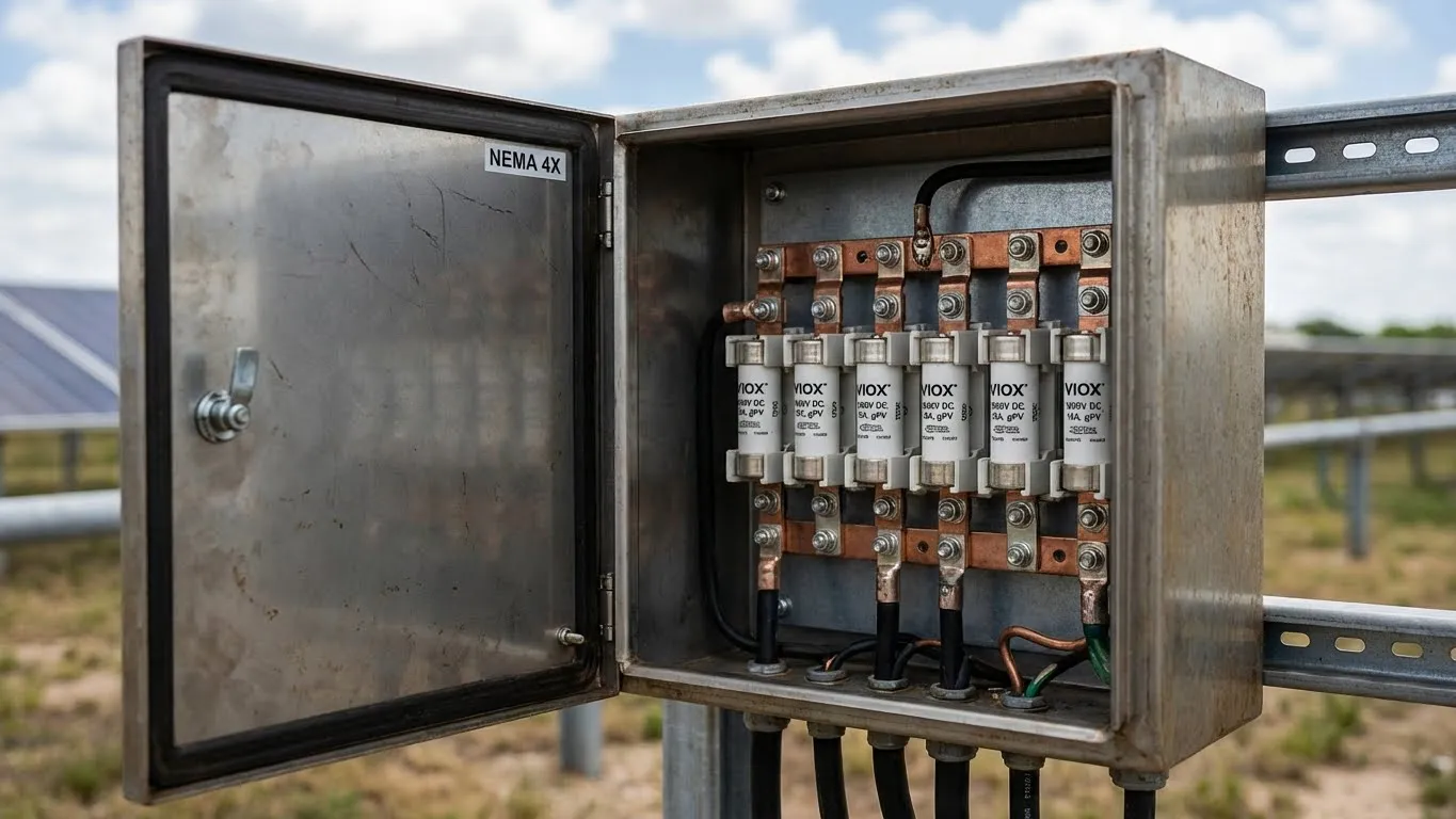
IEC 60269-6 and gPV Fuse Requirements
While sizing calculation is vital, the type of fuse selected is equally critical. For photovoltaic applications, you must use fuses with a gPV characteristic according to IEC 60269-6.
Unlike standard AC fuses or general-purpose DC fuses, gPV fuses are designed to interrupt low overcurrents (typically 1.35x to 2x rated current) that are common in PV strings during shading or mismatch events.
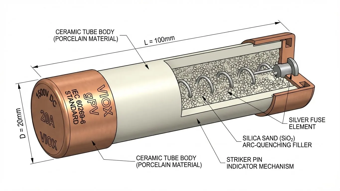
Why gPV Matters for Bifacial
Bifacial modules can sustain currents slightly above their rating for long periods during high-albedo days. A non-gPV fuse might fatigue under this continuous thermal load, leading to premature failure. Furthermore, the high DC voltages (1000V or 1500V) require specific arc-quenching capabilities found in ceramic gPV fuses.
For a deeper comparison of fuse materials, read our article on Glass Fuse vs. Ceramic Fuse Safety Guide.
Comprehensive Calculation Methodology
To size fuses for a bifacial system, follow this step-by-step engineering process.
Step 1: Determine the Reference $I_{sc}$
Consult the module datasheet. Look for the “Bifacial Nameplate Irradiance” or specific data tables showing $I_{sc}$ at different gain levels (e.g., 10%, 20%, 30%). If this data is unavailable, a conservative engineer typically assumes a 20-25% gain for calculations to ensure safety, unless site-specific albedo modeling proves otherwise.
Step 2: Apply NEC 690.8 Factors
Calculate the minimum Overcurrent Protection Device (OCPD) rating.
$$I_{OCPD} = I_{sc, bifacial} \times 1.25 \times 1.25$$
Step 3: Check Module Maximum Series Fuse Rating
Crucially, the selected fuse must not exceed the “Maximum Series Fuse Rating” listed on the module datasheet. This creates a design window:
- Floor: Calculated minimum OCPD size (to prevent nuisance tripping).
- Ceiling: Module Maximum Series Fuse Rating (to protect the module).
If the calculated value exceeds the module’s maximum rating, you cannot simply increase the fuse size. You may need to increase the number of strings (reduce parallel connections) or consult the module manufacturer for updated certifications.
For systems combining multiple strings, ensure you understand the requirements for parallel connections outlined in our guide: Solar PV Fuse Requirements: NEC 690.9 Parallel Strings.
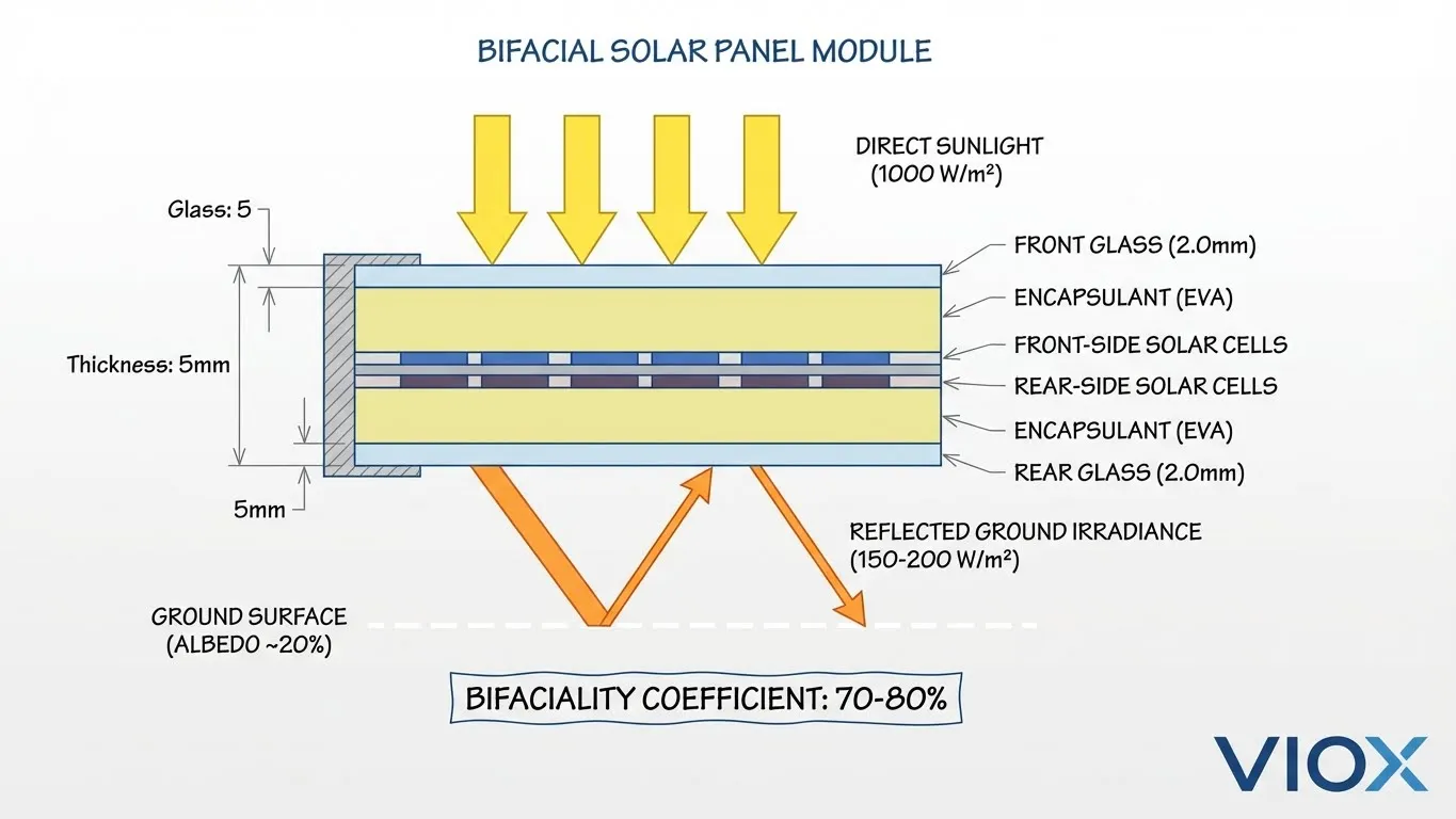
Table 2: Fuse Sizing Examples for Different Bifacial Module Ratings
| Module Front $I_{sc}$ | Bifacial Gain Used | Adjusted $I_{sc}$ | Minimum Fuse Calculation ($I \times 1.56$) | Next Standard Fuse Size |
|---|---|---|---|---|
| 10 A | 10% | 11.0 A | 17.16 A | 20 A |
| 15 A | 15% | 17.25 A | 26.91 A | 30 A |
| 18 A | 20% | 21.6 A | 33.70 A | 35 A or 40 A |
| 20 A | 25% | 25.0 A | 39.00 A | 40 A |
Temperature Derating: The Silent Fuse Killer
Fuses are thermal devices; they operate by melting when they get too hot. Consequently, high ambient temperatures affect their current-carrying capability. Rooftop solar installations often experience temperatures exceeding 60°C or 70°C.
For bifacial modules, the extra current generates extra heat within the fuse link ($P = I^2R$). If you install a fuse rated for 25A in a combiner box that reaches 60°C, that fuse might effectively derate to 20A or less.
When sizing for bifacial systems, apply a temperature derating factor ($K_t$) from the fuse manufacturer’s datasheet:
$$I_{fuse, final} = \frac{\text{Calculated Min Current}}{K_t}$$
Failure to account for temperature is a primary cause of fuse fatigue in hot climates. Learn more about protecting cabling and fuses in harsh environments in our Ground Mount Solar Cable Fuse Sizing Guide.
Real-World Design Considerations
Table 3: Bifacial Gain Factors by Installation Type and Albedo
| Surface Material | Albedo (%) | Typical Current Gain | Recommended Safety Margin |
|---|---|---|---|
| Grass / Soil | 15-20% | 5-7% | Low |
| Concrete / Sand | 20-30% | 7-10% | Medium |
| White Membrane Roof | 60-80% | 15-20% | High |
| Snow | 80-90% | 20-30%+ | Very High |
Combiner Box Selection
The extra current from bifacial modules also impacts the busbars and thermal management of the combiner box. When selecting a combiner box, ensure the enclosure rating and internal busbars are sized for the bifacial total current, not just the front-side rating. For expansion planning, see our Solar Combiner Box Sizing Guide.
Overcurrent vs. Short Circuit
It is important to distinguish between overload protection and short circuit protection. Bifacial gain increases the operating current closer to the overload threshold. Using breakers or fuses with adjustable trip settings can sometimes offer more flexibility than fixed fuses. For a comparison of protection devices, refer to PV DC Protection Explained: MCBs, Fuses, and SPDs.
Common Mistakes to Avoid
- Ignoring Rear-Side Gain: Sizing strictly off the front label is the #1 error. Always add the expected bifacial gain.
- Double-Counting Safety Factors: Some engineers apply the 1.25 factor twice unnecessarily. Stick to the formula: $I_{sc, adjusted} \times 1.56$.
- Exceeding Module Max Series Fuse Rating: Prioritizing the calculated high current while ignoring the module’s safety limit can void warranties and create fire risks.
- Neglecting Temperature Derating: A fuse sized perfectly for 25°C will likely fail at 65°C inside a rooftop combiner box.
Table 4: NEC Multiplication Factors Summary
| Factor | Value | Purpose |
|---|---|---|
| Bifacial Gain | Variable (1.10 – 1.30) | Accounts for rear-side irradiance |
| High Irradiance (690.8(A)(1)) | 1.25 | Accounts for solar intensity > 1000 W/m² |
| Continuous Duty (690.8(B)) | 1.25 | Prevents fuse heating/fatigue over >3 hours |
| Total Standard Multiplier | 1.56 | Combined safety factor for calculation |
FAQ Section
Q: Why do bifacial panels need different fuse sizing than monofacial panels?
A: Bifacial panels generate current from both sides. This additional current raises the effective Short Circuit Current ($I_{sc}$) of the circuit. Fuses sized only for the front-side output may trip during peak sunlight hours when ground reflection is high.
Q: How do I determine the correct Bifacial Gain Factor (BGF) for my project?
A: Ideally, use site-specific simulation software (like PVSyst) that accounts for albedo, pitch, and height. Without simulation, a conservative estimate of 15-20% gain is often recommended for sizing safety equipment, provided it stays within the module’s maximum ratings.
Q: What if the calculated fuse size exceeds the module’s Maximum Series Fuse Rating?
A: You cannot install a fuse larger than the module’s rating. You must redesign the string configuration (e.g., fewer strings in parallel) or select a module with a higher series fuse rating.
Q: Can I use standard AC fuses for bifacial solar panels?
A: No. You must use fuses rated for DC (typically 1000V or 1500V) with a gPV characteristic. AC fuses cannot reliably extinguish DC arcs and may fail catastrophically.
Q: How does temperature affect my fuse choice?
A: Fuses are thermal devices. In high ambient temperatures (common in solar), they trip at lower currents. You must divide your calculated current by the manufacturer’s temperature derating factor to select the correct fuse amperage.
Q: Is the 1.56 factor required by NEC 690.8 sufficient for bifacial panels?
A: The 1.56 factor applies to the module current. For bifacial panels, you must apply this factor to the adjusted current (Front $I_{sc}$ + Rear Gain), not just the front-side $I_{sc}$.
Key Takeaways
- Bifacial Gain is Real Amperage: Treat rear-side gain as continuous current that contributes to heat and load, not just a temporary spike.
- Adjust $I_{sc}$ First: Calculate the total effective $I_{sc}$ (Front + Rear) before applying NEC 1.56 safety factors.
- Mind the Gap: Ensure your fuse rating is high enough to prevent nuisance tripping but low enough to obey the Module Maximum Series Fuse Rating.
- gPV is Mandatory: Always verify that fuses satisfy IEC 60269-6 standards for photovoltaic applications; never substitute with standard loads.
- Albedo Matters: The lighter the ground surface (e.g., white roofs, snow), the higher the current gain—size your OCPD accordingly.
- Watch the Heat: Ambient temperature in combiner boxes significantly reduces fuse capacity; apply derating factors to avoid fatigue failure.
