
Why Most ATS Specifications Miss the Critical Coordination Factor
When specifying an automatic transfer switch, most electrical engineers focus on the obvious parameters: continuous current rating, transfer time, and voltage compatibility. Yet a critical oversight lurks in thousands of installations worldwide—the coordination nightmare between upstream circuit breakers and the ATS’s short-circuit withstand capability. This gap becomes catastrophic during fault conditions when a mismatched protection scheme either causes nuisance trips that black out entire facilities or fails to protect equipment altogether.
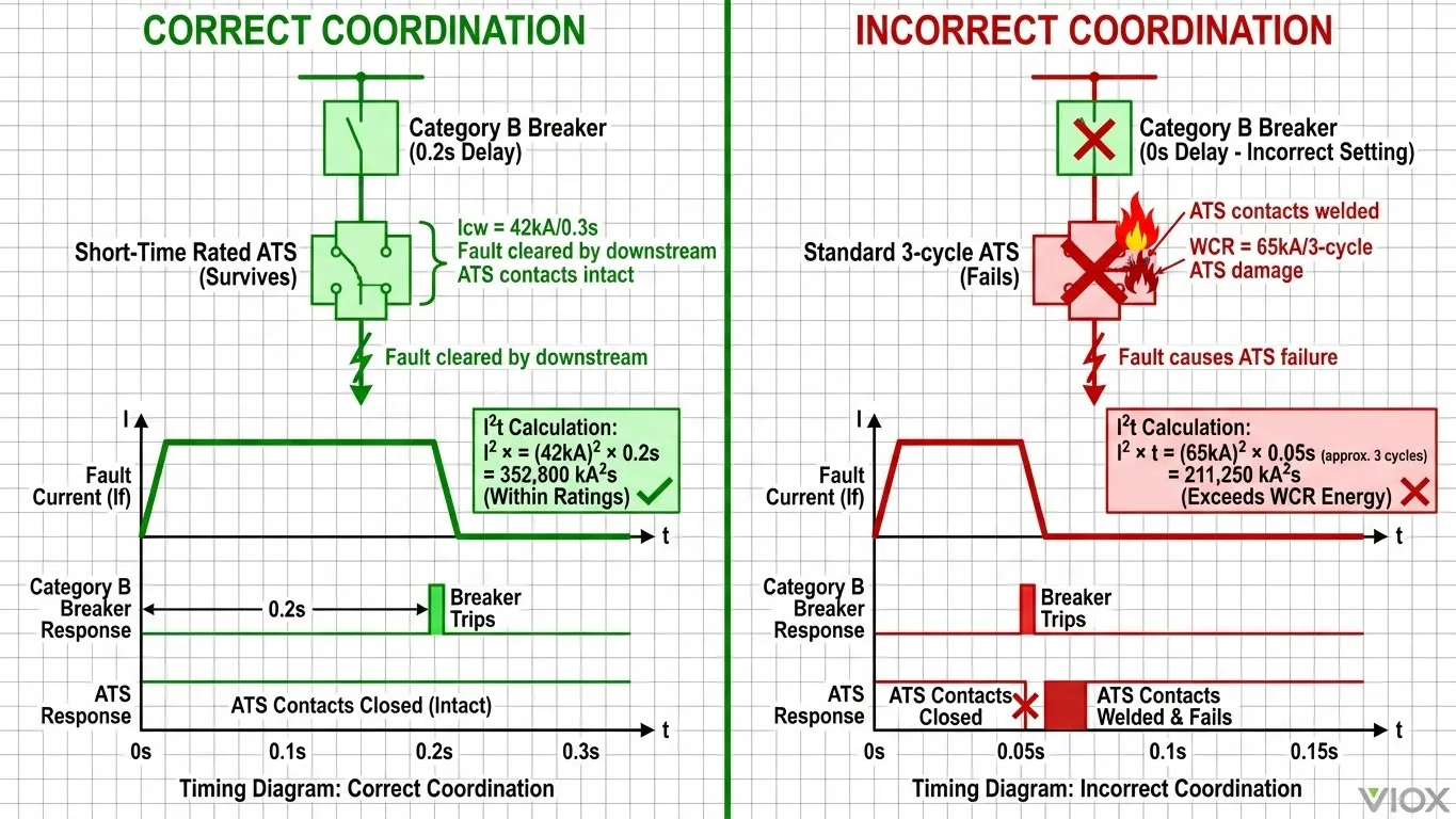
The root problem lies in the complex interplay between circuit breaker selectivity categories, short-time withstand current (Icw) ratings, and ATS fault-current tolerance. When engineers specify Category B circuit breakers with intentional time delays to achieve selective coordination, they create a scenario where the ATS must survive the full fault current during that delay window—often 100 milliseconds to 1 second. Standard 3-cycle rated ATS units simply cannot withstand these extended fault durations, leading to contact welding, arc damage, or complete transfer switch failure.
This comprehensive guide provides the engineering-level insight you need to master ATS-breaker coordination, understand the distinction between Category A and B protection devices, apply time-based selectivity principles correctly, and specify transfer switches that align with your overcurrent protection strategy—whether you’re designing emergency power systems for hospitals, data centers, or critical industrial facilities.
Part 1: Understanding Circuit Breaker Categories and Icw Ratings
1.1 Category A vs Category B Circuit Breakers: The Foundation of Coordination Strategy
The IEC 60947-2 standard divides low-voltage circuit breakers into two fundamental protection categories that determine their coordination behavior. Category A circuit breakers operate with instantaneous magnetic trip functions and provide no intentional short-time delay. These devices—typically molded-case circuit breakers (MCCBs) and miniature circuit breakers (MCBs)—are engineered to trip as rapidly as possible when fault current is detected, usually within 10-20 milliseconds. Category A breakers do not carry an Icw rating because they’re designed to interrupt, not withstand, short-circuit currents.
You’ll deploy Category A breakers in motor feeder circuits, final distribution panels, and branch circuit protection where the goal is immediate fault clearance. The fast-acting characteristic protects cables and downstream equipment from thermal and mechanical stress, but it offers no coordination flexibility. When a fault occurs anywhere in the protected zone, the Category A breaker trips—period.
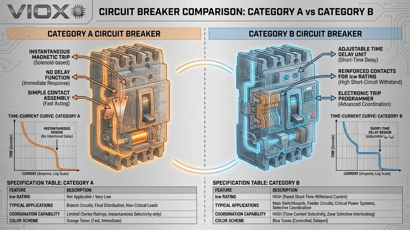
Category B circuit breakers, in contrast, incorporate adjustable short-time delay functions that enable sophisticated time-based coordination strategies. These devices—predominantly air circuit breakers (ACBs) and certain high-performance MCCBs—can be programmed to intentionally delay their trip response between 0.05 and 1.0 seconds when fault current is detected. This delay window allows downstream protection devices to clear faults first, achieving true selective coordination. Category B breakers must carry an Icw rating that certifies their ability to withstand the fault current during the delay period without sustaining damage.
| Feature | Category A Breakers | Category B Breakers |
|---|---|---|
| Trip Characteristic | Instantaneous (10-20ms) | Adjustable delay (0.05-1.0s) |
| Icw Rating | Not provided | Mandatory rating |
| Typical Types | MCB, standard MCCB | ACB, advanced MCCB |
| Primary Use | Feeder/branch circuits | Main incomers, bus-tie |
| Coordination Method | Current magnitude only | Time-delayed selectivity |
| Relative Cost | Lower | Higher |
| Application Complexity | Simple | Requires coordination study |
Understanding this fundamental distinction is essential when selecting circuit protection for ATS installations, because the breaker category directly determines the ATS rating requirements and coordination complexity.
1.2 What is Icw (Short-Time Withstand Current)?
Rated short-time withstand current (Icw) represents the maximum RMS symmetrical short-circuit current that a Category B circuit breaker can carry for a specified duration without tripping or sustaining thermal or electrodynamic damage. IEC 60947-2 defines standard test durations of 0.05, 0.1, 0.25, 0.5, and 1.0 seconds, with the breaker remaining closed throughout the fault while monitoring for contact degradation, insulation failure, or mechanical deformation.
The physical stresses during this withstand period are extreme. Thermally, the fault current generates I2t energy that heats conductors, contacts, and busbars according to the square of the current multiplied by time. A 50kA fault sustained for 0.5 seconds produces 1,250 MJ/s of thermal energy that must be absorbed without exceeding material temperature limits. Electrodynamically, the magnetic fields generated by fault currents create repulsive forces between parallel conductors that can exceed several tons per meter—forces that must not bend busbars or damage contact assemblies.
Why Icw matters critically for ATS coordination: When you configure an upstream Category B breaker with a 0.2-second short-time delay to achieve selectivity with downstream feeders, every device in series—including the ATS—must withstand the fault current for that entire delay. A breaker rated at Icw = 42kA for 0.5s can survive 42,000 amperes for half a second, but if your ATS lacks equivalent short-time withstand capability, it becomes the weak link that fails under coordination schemes designed to enhance system reliability.
| Breaker Type | Typical Icw Range | Common Time Ratings | Application Example |
|---|---|---|---|
| Heavy-duty MCCB | 12-50 kA | 0.05s, 0.1s, 0.25s | Distribution switchboard main |
| Air Circuit Breaker (ACB) | 30-100 kA | 0.1s, 0.25s, 0.5s, 1.0s | Service entrance, bus coupling |
| Compact ACB | 50-85 kA | 0.25s, 0.5s, 1.0s | Generator main, UPS input |
Pro Tip: The Icw value on a breaker’s datasheet typically assumes the maximum delay time (often 1.0s). If your coordination study requires shorter delays (e.g., 0.1s), you may be able to use a breaker with lower Icw rating, since the thermal stress I2t at 0.1s is significantly less than at 1.0s. Always verify that I2t(fault) < I2cw × t(delay).
1.3 Related Ratings: Icu, Ics, and Icm
Circuit breaker short-circuit performance involves four interrelated ratings that must be understood as a coordinated system, not isolated specifications.
Icu (Ultimate short-circuit breaking capacity) defines the maximum RMS symmetrical fault current the breaker can safely interrupt under test conditions specified in IEC 60947-2. After breaking at Icu, the breaker may be damaged and unsuitable for continued service, but it must not create a safety hazard. Think of Icu as the survival threshold—the breaker lived through it, but just barely. For critical installations, you want available fault current to remain well below Icu under all operating scenarios.
Ics (Service short-circuit breaking capacity) represents the fault current level at which the breaker can interrupt and then continue normal operation with full performance capability intact. The IEC standard defines Ics as a percentage of Icu—typically 25%, 50%, 75%, or 100% depending on breaker design and intended application. For mission-critical transfer switch systems in hospitals, data centers, or emergency power installations, specifying breakers with Ics = 100% of Icu ensures that even maximum-rated fault events don’t degrade protection system integrity.
Icm (Rated making current) specifies the maximum peak instantaneous current the breaker can safely close onto at rated voltage. This rating becomes critical during ATS transfer operations and generator synchronization sequences where you may be switching into an existing fault condition. The relationship between Icm and Icu depends on the power factor of the fault loop: Icm = k × Icu, where k ranges from 1.5 (high impedance, resistive faults) to 2.2 (low impedance, inductive faults typical in power systems). For a breaker rated Icu = 50kA at cos φ = 0.3, expect Icm ≈ 110kA peak.
Common Mistake: Engineers often verify that the upstream breaker’s Icu exceeds available fault current but fail to check Icw adequacy when time delays are employed. For generator-ATS-utility coordination schemes, this oversight can be catastrophic—the breaker survives the fault (meets Icu), but the ATS welded contacts during the 0.3-second delay window because nobody verified short-time ratings.
Part 2: Selectivity Principles and Coordination Strategies
2.1 What is Selectivity (Discrimination)?
Selectivity, also termed discrimination or coordination, describes the strategic arrangement of overcurrent protection devices in a distribution system such that only the protective device immediately upstream of a fault operates, while all other upstream devices remain closed. The engineering objective is to minimize the scope of power interruption—isolate the smallest possible section of the installation affected by the fault while maintaining service continuity to all other loads.
Consider a distribution system supplying twenty manufacturing cells through individual feeder breakers, all supplied from a common main breaker. Without selectivity, a ground fault in Cell #7 might trip the main breaker, blackening out all twenty cells and halting production across the entire facility. With proper selectivity, only the Cell #7 feeder breaker opens, containing the outage to one cell while the other nineteen continue operating.
Two fundamental mechanisms enable selectivity: current selectivity (also called ampere selectivity or discrimination by magnitude) and time selectivity (discrimination by intentional delay). Most coordinated protection schemes employ both mechanisms across different fault current ranges, achieving partial selectivity at high fault levels and total selectivity at lower currents where system impedance naturally differentiates fault magnitudes at different locations.
2.2 Current Selectivity: Natural Coordination by Magnitude
Current selectivity exploits the natural impedance of cables and transformers to create fault current magnitude differences between distribution levels. A fault at the load end of a 50-meter feeder cable draws significantly less current than a fault at the feeder origin due to cable impedance. By setting the upstream breaker’s instantaneous trip threshold above the maximum fault current the downstream breaker will see, you achieve selectivity automatically—the downstream device trips at lower currents, the upstream device only responds to faults in its protected zone.
Example: A 400A main breaker feeding a 100A feeder breaker through 75 meters of 50mm² copper cable. Short-circuit current at the main breaker location might reach 35kA, but cable impedance limits the maximum fault current at the feeder breaker’s load terminals to approximately 12kA. Setting the main breaker’s instantaneous trip at 25kA and the feeder’s magnetic trip at 15kA creates a selectivity window—any fault drawing less than 25kA is cleared by the feeder breaker alone.
The limitation of current selectivity is the selectivity limit—the fault current level where the time-current curves of upstream and downstream devices intersect. Below this current, only the downstream device operates. Above it, both devices may trip simultaneously (loss of selectivity). For a typical MCCB coordination pair, selectivity limits range from 3-15kA depending on breaker ratings and manufacturer-provided selectivity tables.
Partial selectivity exists when coordination is maintained up to the selectivity limit but lost at higher fault currents. Total selectivity means coordination extends to the full breaking capacity of the downstream device. For installations where automatic transfer switch fault protection must guarantee upstream breaker stability during downstream faults, total selectivity is often mandated by specification or code requirements.
2.3 Time Selectivity with Icw: Engineering Intentional Delays
Time selectivity introduces intentional delays in upstream protection devices to create a coordination window during which downstream devices can clear faults first. This approach is essential when current selectivity alone cannot achieve total coordination, particularly at high fault current levels near the power source where impedance differentiation between levels is minimal.
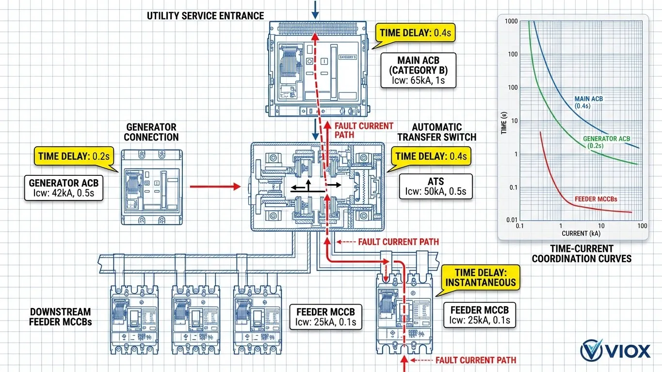
The principle is straightforward: configure the upstream Category B breaker with a short-time delay (typically 0.1s, 0.2s, or 0.4s), then set downstream breakers with progressively shorter delays or instantaneous trip. When a fault occurs, the downstream breaker nearest the fault operates within 10-30ms while the upstream breaker intentionally holds closed for its preset delay. If the downstream breaker successfully clears the fault, the upstream device never trips. If the downstream device fails or the fault exceeds its interrupting capacity, the upstream breaker operates after its delay, providing backup protection.
Critical requirement: The upstream Category B breaker must possess adequate Icw rating to survive the fault current during the entire delay period. The governing equation is:
I2t(fault) < I2cw × t(delay)
Where I2t(fault) represents the thermal energy from the fault (current squared × time) and I2cw × t(delay) represents the breaker’s withstand capability.
| Coordination Level | Device Type | Trip Delay Setting | Required Icw @ 30kA Fault |
|---|---|---|---|
| Level 3 – Main Incomer | ACB 1600A | 0.4s delay | 42kA for 0.5s |
| Level 2 – Sub-distribution | MCCB 400A | 0.2s delay | 35kA for 0.25s |
| Level 1 – Feeder | MCCB 100A | Instantaneous | Not applicable (Category A) |
In this cascade, a 30kA fault at Level 1 is cleared by the 100A feeder breaker in 20ms. The 400A breaker waits 0.2s (must withstand 30kA for at least 0.25s per its Icw rating), sees the fault cleared, and remains closed. The 1600A main breaker waits 0.4s (must withstand 30kA for at least 0.5s), also remains closed. Result: only the faulted feeder loses power.
Common Mistake: Engineers sometimes disable instantaneous trip on the main breaker to “improve coordination” without verifying that all series-connected equipment—including the ATS—can withstand the extended fault duration. This creates a protection gap where equipment damage occurs before the delayed trip activates.
2.4 Selectivity in Critical Systems: NEC and Life Safety Requirements
The National Electrical Code (NEC) Article 700.28 mandates selective coordination for emergency system overcurrent devices, requiring “coordination accomplished by the selection and installation of overcurrent protective devices and their ratings or settings for the full range of available overcurrents from overload to the maximum available fault current.” Similar requirements exist in NEC Article 517 for healthcare facilities and Article 708 for critical operations power systems.
These code requirements fundamentally impact ATS specification strategies. To achieve code-compliant selective coordination in emergency power distribution, engineers must often disable or significantly delay the instantaneous trip function on upstream breakers serving the ATS. A main breaker that ordinarily would trip in 1-2 cycles (16-32ms) during a 40kA fault might be set to delay 0.3 seconds to coordinate with downstream emergency feeders.
This creates the coordination paradox: the very delays required for code-compliant selectivity subject the ATS to extended fault exposure that standard 3-cycle withstand ratings cannot survive. Understanding transfer switch short-circuit ratings becomes mandatory, not optional, in emergency system design. You must either specify short-time rated ATS units capable of surviving the coordination delay or redesign the protection scheme using current-limiting devices (fuses) that provide inherent selectivity without time delays.
Pro Tip: Before finalizing breaker settings for emergency systems, conduct a complete coordination study that includes the ATS short-circuit withstand rating as a constraint. Many engineers discover too late that achieving NEC 700.28 compliance with their chosen breaker settings requires upgrading to a more expensive short-time rated transfer switch—a change order that could have been avoided with proper early-phase coordination analysis.
Part 3: ATS Short-Circuit Ratings and Coordination Requirements
3.1 ATS Withstand and Closing Ratings (WCR): Understanding the Fundamentals
Every automatic transfer switch carries a withstand and closing rating (WCR) that defines the maximum prospective short-circuit current the transfer switch can safely withstand when protected by a specified overcurrent protective device (OCPD). This rating is not a standalone equipment capability—it represents a tested and certified combination of the ATS with specific types and settings of upstream protection.
Standard ATS ratings are typically based on 3-cycle withstand testing (approximately 50 milliseconds at 60Hz), during which the transfer switch must endure the fault current while the upstream OCPD opens without suffering contact welding, insulation failure, or mechanical damage. Testing follows UL 1008 (Standard for Transfer Switch Equipment) protocols that subject the device to worst-case fault scenarios including closing onto existing faults and faults occurring while contacts are closed.
The ATS manufacturer’s technical data typically presents WCR in two formats:
“Specific breaker” ratings certify the ATS for use with explicitly identified circuit breaker models, ratings, and trip settings. For example: “100kA SCCR when protected by Square D Model HDA36100, 100A frame, magnetic trip set at 10×In, with instantaneous trip enabled.” This provides maximum rating but limits design flexibility.
“Any breaker” ratings certify the ATS for use with any circuit breaker meeting specified characteristics—typically requiring instantaneous trip capability and 3-cycle clearing. For example: “42kA SCCR when protected by any circuit breaker rated ≥100A with instantaneous trip and 3-cycle maximum clearing time.” This offers design flexibility but often at reduced fault current ratings.
Common WCR values for commercial and light industrial ATS units range from 10kA to 100kA, with typical ratings at 22kA, 42kA, 65kA, and 85kA depending on frame size and construction:
| ATS Frame Size | Typical 3-Cycle WCR Range | Common OCPD Requirement |
|---|---|---|
| 30-100A | 10-35 kA | Any breaker, instantaneous trip |
| 150-400A | 22-65 kA | Specific breaker or current-limiting fuse |
| 600-1200A | 42-100 kA | Specific breaker with documented settings |
| 1600-3000A | 65-200 kA | Engineered coordination, often fused |
Pro Tip: The term “any breaker” is somewhat misleading—it really means “any breaker with instantaneous trip that clears in 3 cycles or less.” This excludes Category B breakers configured with short-time delays, a restriction that catches many engineers by surprise when they attempt to achieve selective coordination.
3.2 Short-Time Rated ATS: Engineering Solutions for Time-Delayed Coordination
To enable coordination with Category B circuit breakers employing intentional time delays, ATS manufacturers offer short-time rated transfer switches tested to withstand specified fault currents for extended durations up to 30 cycles (0.5 seconds). These specialized units undergo rigorous testing per UL 1008 provisions that verify contact integrity, arc interruption capability, and structural stability during sustained fault conditions that would destroy standard transfer switches.
Typical short-time ratings follow a time-current relationship where higher currents are tolerated for shorter durations:
- 30kA for 0.3 seconds (18 cycles)
- 42kA for 0.2 seconds (12 cycles)
- 50kA for 0.1 seconds (6 cycles)
The engineering trade-offs for short-time rated ATS units are significant. Construction requires heavier contact assemblies with enhanced contact materials (often silver-tungsten alloys), increased contact pressure spring forces to resist electromagnetic repulsion, robust arc chutes with advanced quenching, and reinforced frame structures to withstand electrodynamic forces. These enhancements typically increase the ATS cost by 30-60% compared to standard 3-cycle rated equivalents and may increase physical dimensions by 20-40%.
Availability is another constraint. Most manufacturers limit short-time ratings to larger frames (≥400A) where the physical size accommodates reinforced construction. Some ratings are available only in three-pole configurations for single-phase applications due to the complexity of achieving uniform short-time withstand across four-pole designs where the neutral pole faces different thermal stress patterns.
When to specify short-time rated ATS: Critical applications requiring selective coordination per NEC Article 700.28 (emergency systems), healthcare facilities under NEC Article 517, data centers with tier III/IV reliability requirements, or any installation where automatic transfer switch coordination with time-delayed breakers is necessary to maintain service continuity to critical loads.
3.3 ATS Coordination with Circuit Breakers: Decision Framework
The coordination relationship between an ATS and its upstream OCPD determines not only fault protection adequacy but also system reliability during normal and emergency operations. Understanding the decision framework prevents costly specification errors.
Scenario 1: Category A Breaker Upstream (Instantaneous Trip)
This represents the simplest and most common coordination case. The upstream Category A breaker operates with instantaneous magnetic trip, clearing faults in 1-3 cycles (16-50ms). The ATS specification requirement is straightforward:
ATS WCR ≥ Available fault current at ATS location
If short-circuit calculations indicate 35kA available at the ATS, specify an ATS with minimum 35kA WCR for the chosen breaker type (specific or “any breaker”). The ATS need not have short-time rating since the fault clears within the standard 3-cycle test window.
Scenario 2: Category B Breaker with Time Delay (Selective Coordination)
This scenario introduces significant complexity. The upstream Category B breaker is configured with short-time delay (typically 0.1s to 0.5s) to coordinate with downstream feeders. During this delay, the ATS must withstand the full fault current without the breaker providing interruption.
The specification requirements become:
- ATS must have short-time rating matching or exceeding the breaker delay setting
- ATS short-time current rating ≥ Available fault current
- Breaker Icw rating ≥ Available fault current for the delay duration
- Verify I2t energy: I2t(fault) < I2cw(breaker) × t(delay) AND I2t(fault) < I2cw(ATS) × t(rating)
Example: An engineer specifies a 600A ATS protected by an 800A ACB configured with 0.3s short-time delay for downstream coordination. Available fault current at the ATS location is 42kA from the utility source. Required specifications:
- ATS: Minimum 42kA short-time withstand for 0.3s (or higher rating with shorter time if I2t analysis confirms adequate)
- ACB: Icw ≥ 42kA for 0.3s minimum (Icw = 50kA for 0.5s would be adequate)
- Verify: (42kA)2 × 0.3s = 529 MJ/s < breaker and ATS I2t capabilities
| Decision Factor | Category A Protection | Category B Time-Delayed Protection |
|---|---|---|
| ATS Rating Type | Standard 3-cycle WCR | Short-time rated WCR required |
| Coordination Complexity | Simple | Complex—requires I2t analysis |
| Relative Cost | Lower | 30-60% higher for short-time ATS |
| Design Risk | Low—standard application | Higher—requires detailed study |
| Application Example | Small commercial, residential | Hospitals, data centers, emergency systems |
3.4 Common Coordination Mistakes: What Goes Wrong in Practice
After reviewing hundreds of ATS installations and coordination studies, several recurring errors emerge that compromise safety and reliability:
Mistake #1: Using standard 3-cycle ATS with time-delayed upstream breaker. This is the single most common error. An engineer specifies selective coordination requiring a 0.2s breaker delay but fails to upgrade the ATS specification from standard to short-time rated. During the first significant fault, the ATS contacts weld closed or sustain arc damage because they were exposed to fault current for 200ms—four times their rated withstand duration. The system now has a failed transfer switch and potentially no emergency power capability.
Mistake #2: Insufficient SCCR documentation on field markings. NEC 110.24 requires field marking of available fault current on service equipment. For ATS installations, the field marking must account for the ATS’s dependence on upstream OCPD characteristics. Many installations incorrectly mark only the calculated fault current without documenting that the ATS rating is valid only with specific breaker settings. When maintenance personnel later modify breaker settings (perhaps enabling instantaneous trip that was previously disabled), they invalidate the ATS rating without realizing it.
Mistake #3: Ignoring NEC 700.28 selective coordination requirements for emergency systems. Engineers sometimes apply standard distribution protection practices to emergency systems without recognizing that NEC 700.28 mandates selective coordination. The resulting design uses instantaneous trip on all breakers (no selectivity) or achieves selectivity only in the overload range but not under short-circuit conditions (partial selectivity). Code compliance failures during inspection require costly redesign.
Mistake #4: Not accounting for generator vs utility source impedance differences. Available fault current from a standby generator is typically 4-10 times lower than from utility service due to generator subtransient reactance. An ATS protected by a 65kA rated breaker may see 52kA from the utility but only 15kA from the generator. Engineers sometimes specify ATS ratings based solely on utility fault levels, then discover during generator load testing that generator source coordination creates different time-current coordination challenges requiring separate analysis.
Pro Tip: Before finalizing any ATS specification for a critical application, conduct a complete coordination study that includes both utility and generator fault sources, models all protective device time-current curves including breaker delay settings, verifies ATS withstand capabilities for worst-case scenarios, and documents OCPD settings that maintain the validated coordination. This study should be stamped by a licensed PE and included in project closeout documents.
Part 4: Practical Specification and Design Strategies
4.1 Step-by-Step Coordination Process: Engineering Methodology
Successful ATS-breaker coordination requires systematic analysis following a proven methodology. Here’s the engineering process that ensures reliable results:
Step 1: Calculate Available Fault Current at ATS Location
Perform short-circuit analysis using available fault current at the service entrance, transformer secondary, or generator terminals, then calculate fault current at the proposed ATS location accounting for cable impedance, transformer impedance, and source impedance. Analyze both utility and generator sources separately, as they present dramatically different fault current levels. Use industry-standard software (SKM PowerTools, ETAP, EASYPOWER) or hand calculation methods per IEEE 141 (Red Book).
Step 2: Determine Selective Coordination Requirements
Review applicable codes (NEC Articles 700, 517, 708), owner’s requirements specifications, and operational criticality analysis. Determine whether selective coordination is mandatory (emergency systems, healthcare), recommended (critical processes), or optional (general distribution). Document the required coordination level: total selectivity (all fault currents) or partial selectivity (up to selectivity limit).
Step 3: Select Upstream OCPD Type and Settings
Based on coordination requirements, choose the appropriate protection strategy:
- If instantaneous trip acceptable: Category A breaker is appropriate—simpler and lower cost. Proceed to Step 4 with standard ATS rating verification.
- If time delay needed for selectivity: Category B breaker required. Determine necessary delay settings (0.1s, 0.2s, 0.4s) based on coordination study with downstream devices. Verify breaker has adequate Icw rating for selected delay at available fault current. Recognize that short-time rated ATS will be required.
Step 4: Match ATS Rating to OCPD Characteristics
Cross-reference the OCPD selection with ATS ratings:
- Time-delayed OCPD → Short-time rated ATS required: Select ATS with short-time withstand rating ≥ available fault current and time rating ≥ breaker delay setting. Example: 0.2s breaker delay requires ATS with minimum 0.2s short-time rating (or higher current rating with shorter time if I2t analysis validates).
- Instantaneous OCPD → Standard 3-cycle ATS acceptable: Verify ATS WCR ≥ available fault current for the specific or “any breaker” rating category matching your OCPD selection.
Step 5: Verify Downstream Coordination Chain
Confirm that the entire distribution system from utility service through ATS to load feeders maintains coordination at all levels. Plot time-current curves for all devices in series. Verify adequate time separation (minimum 0.1s between adjacent levels) and current magnitude separation (ratio ≥ 1.6:1 for current selectivity). Check that no curve intersections occur within the operating fault current range.
4.2 Engineering Best Practices: Professional Standards
Implementing these practices distinguishes professional engineering from specification roulette:
Always conduct comprehensive short-circuit study before specifying ATS and OCPDs. Never rely on rule-of-thumb estimates or “typical” values. Available fault current varies dramatically based on utility capacity, transformer size, cable length, and source impedance. A 2% error in impedance calculation can produce a 30% error in fault current, potentially invalidating all protective device ratings.
Document OCPD type, settings, and ATS rating relationship in construction documents. Create a protection coordination report that explicitly states: “ATS Model XYZ rated 65kA SCCR is valid ONLY when protected by Breaker Model ABC, 800A frame, with settings: Ir=0.9×In, Isd=8×Ir, tsd=0.2s, Ii=OFF (instantaneous disabled).” Include this information on one-line diagrams and panel schedules. Field-mark equipment per NEC 110.24 with dependency noted.
Consider future load growth and fault level changes. Utility fault current may increase if substations are upgraded or additional generation connects nearby. Specify protective device ratings with 20-30% margin above calculated values to accommodate reasonable future growth without requiring equipment replacement.
Use manufacturer coordination tables and testing data. Don’t assume coordination exists based on curve plotting alone—energy selectivity and current-limiting characteristics affect coordination in ways time-current curves don’t reveal. Reference manufacturer-provided selectivity tables that document tested combinations, or request factory testing data for custom applications.
Field verify installed OCPD settings match design intent. Construction quality control must include verification that electronic trip units are programmed per coordination study, not left at factory defaults. A single incorrect delay setting invalidates months of engineering coordination analysis.
4.3 Cost-Benefit Analysis: Making Intelligent Trade-offs
Short-time rated ATS units command premium pricing—typically 30-60% above equivalent standard-rated models. When does this investment make engineering and economic sense?
Mandatory investment scenarios where short-time rated ATS is non-negotiable:
- Emergency power systems requiring NEC 700.28 selective coordination compliance
- Healthcare facilities under NEC Article 517 (patient care areas)
- Critical operations power systems (COPS) per NEC Article 708
- Mission-critical data centers with tier III/IV reliability specifications
- Any application where applicable codes or contract specifications explicitly require selective coordination
High-value investment scenarios where short-time rated ATS provides operational benefit:
- Manufacturing facilities where production downtime exceeds $10,000/hour
- Commercial buildings with diverse tenants where fault isolation prevents multi-tenant outages
- Campus distribution systems where maintaining partial operation during faults has high value
- Facilities with multiple generator sets where generator paralleling strategies benefit from coordinated protection
Alternative strategies that may provide adequate protection at lower cost:
Current-limiting fuses upstream: Class J, L, or RK1 fuses provide inherent selectivity through their energy-limiting characteristic without time delays. A fused disconnect upstream of the ATS may enable use of standard-rated ATS while achieving excellent coordination. Trade-off: Fuses are single-shot devices requiring replacement after operation, while breakers reset.
Higher impedance sources: Specifying generators or transformers with intentionally higher impedance reduces available fault current at the ATS, potentially allowing standard rating to be adequate even with modest breaker delays. Trade-off: Higher impedance increases voltage drop and may affect motor starting capability.
Zone selective interlocking (ZSI): Advanced communication between breaker trip units enables intelligent selectivity where downstream breakers send “restraint” signals to upstream devices during faults. This can reduce required delay times, potentially allowing standard ATS ratings. Trade-off: Increased system complexity and higher breaker costs.
4.4 VIOX Engineering Support: Technical Resources and Coordination Services
VIOX Electric recognizes that ATS-breaker coordination represents one of the most technically challenging aspects of standby power system design. Our engineering team provides comprehensive support services to ensure your specifications achieve both safety compliance and operational reliability.
Our technical resource library includes detailed application guides covering circuit breaker rating fundamentals, transfer switch selection criteria, and generator-ATS integration strategies. These resources provide the technical depth necessary for informed equipment selection and system design.
For complex coordination challenges, VIOX offers engineering consultation services that include short-circuit analysis verification, time-current coordination studies, SCCR validation, and NEC selective coordination compliance review. Our application engineers work directly with your design team to develop protection schemes that balance safety, reliability, and cost-effectiveness for your specific application requirements.
Contact VIOX technical support to discuss your transfer switch coordination challenges and access our engineering resources. We’re committed to ensuring your standby power systems deliver reliable performance when critical loads demand uninterrupted operation.
FAQ
Q1: What’s the difference between Category A and Category B circuit breakers?
Category A breakers operate with instantaneous trip and no intentional short-time delay—they’re designed to clear faults as quickly as possible (typically 10-20ms). Category B breakers can be configured with adjustable short-time delays (0.05-1.0s) to enable time-based selective coordination, and they carry Icw ratings certifying their ability to withstand fault currents during the delay period. Category A breakers are used for feeders and branch circuits; Category B breakers are deployed at main incomers and bus-tie positions where coordination is required.
Q2: Do all automatic transfer switches have Icw ratings?
No. Only short-time rated ATS units carry Icw specifications. Standard ATS units are rated for 3-cycle (50ms) withstand and do not have Icw ratings since they’re designed for use with instantaneous-trip protection that clears faults within the 3-cycle window. If your application requires coordination with time-delayed circuit breakers, you must specify a short-time rated ATS with Icw rating matching your coordination delay requirements.
Q3: Can I use a standard 3-cycle ATS with a time-delayed circuit breaker?
No—this is a dangerous mismatch that leads to ATS failure. A standard 3-cycle ATS is tested to withstand fault current for approximately 50 milliseconds while the upstream breaker clears. If you configure the upstream breaker with 0.2s delay (200 milliseconds) for selective coordination, the ATS is exposed to fault current for four times its rated withstand duration, causing contact welding, arc damage, or catastrophic failure. Time-delayed breakers require short-time rated ATS units.
Q4: How do I calculate if my ATS can withstand the short-circuit current during breaker coordination?
Verify that the thermal energy (I2t) from the fault is less than both the breaker’s and ATS’s withstand capability: I2t(fault) < I2cw(breaker) × t(delay) AND I2t(fault) < I2cw(ATS) × t(rating). Example: 40kA fault with 0.3s breaker delay produces I2t = (40kA)2 × 0.3s = 480 MJ/s. Your ATS must have short-time rating ≥ 40kA for ≥ 0.3s, and your breaker must have Icw ≥ 40kA for 0.3s minimum. Always include 10-20% safety margin in these calculations.
Q5: What does “selective coordination” mean for ATS installations?
Selective coordination means that during a fault anywhere in the distribution system downstream of the ATS, only the protective device immediately upstream of the fault operates—the ATS upstream breaker remains closed, maintaining power to all loads except the faulted branch. This requires proper selection of circuit breaker types, ratings, and settings, coordinated with the ATS short-circuit withstand capability. NEC Article 700.28 mandates selective coordination for emergency systems, which often drives the requirement for short-time rated ATS units.
Q6: When is a short-time rated ATS required?
Short-time rated ATS is mandatory when: (1) The upstream circuit breaker uses intentional time delays (Category B breaker) for selective coordination, or (2) NEC or contract specifications explicitly require selective coordination for emergency, healthcare, or critical operations power systems. It’s also recommended for any mission-critical application where maintaining maximum service continuity during faults provides operational value that justifies the 30-60% cost premium.
Q7: How does generator source impedance affect ATS coordination?
Generator sources typically present 4-10 times lower fault current than utility sources due to subtransient reactance. This creates two distinct coordination scenarios that must be analyzed separately—one for utility-source faults (higher current, potentially more severe) and one for generator-source faults (lower current, different coordination requirements). Your ATS must be rated for the maximum fault current from either source, and your coordination study must verify selectivity under both scenarios. Some installations require different breaker settings or dual-rated devices to accommodate this difference.
