

في هذه الصفحة
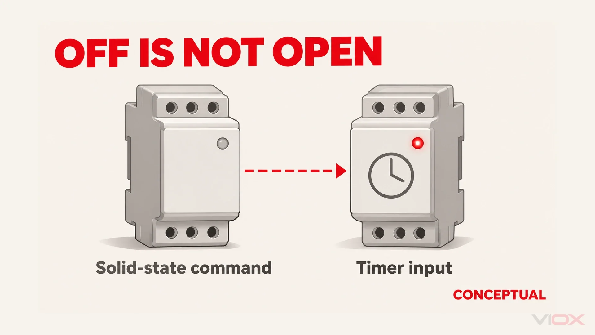
The command can be OFF while the timer input is still active. After checking the supply, selected function and output circuit, investigate timer relay leakage current through the control wiring. A semiconductor output, an illuminated control or coupling along a cable can supply an unwanted signal. That signal may start timing, prevent reset or stop the next trigger being recognized. Find the missing input transition before replacing the timer.
| الأعراض | Investigate first | الأدلة المطلوب جمعها |
|---|---|---|
| Timing starts without a command | An unintended input transition or a supply disturbance | Input and supply behavior at the unwanted start |
| Timing never resets after OFF | A command conductor that remains electrically active | Connected-input residual voltage and the required inactive interval |
السلامة: unintended timing can start machinery. Qualified personnel must secure the machine, isolate relevant sources and verify absence of voltage before moving conductors or components. Energized observations require a controlled test arrangement and suitable instruments. Preserve emergency stops, permissives and other safety functions throughout testing.
Why Electronic Inputs Fall for It
Identify the Interface Before Testing
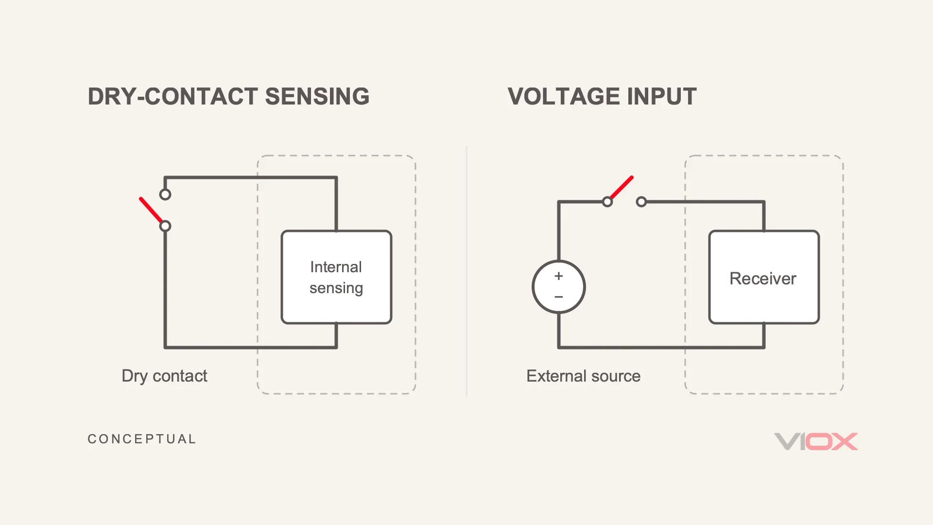
A timer’s operating supply, control input and output contacts are separate interfaces. The input may detect an externally applied voltage, sense an external dry-contact closure, or accept a specified transistor signal. These arrangements require different tests.
In a dry-contact arrangement, the timer provides the sensing excitation; the external contact completes its intended sensing circuit. Applying an unrelated external voltage is not equivalent to closing that contact. A voltage-triggered input instead expects a specified voltage between its signal and reference connections. NPN and PNP interfaces introduce sourcing or sinking requirements; their valid active and inactive states follow the particular circuit.
Terminal lettering alone does not establish the interface. Identify the signal pair, its reference and its active polarity from the drawing. Protective earth is not an assumed signal return. An input can also need a valid inactive interval before it rearms, so an apparently completed timing cycle does not establish that reset occurred.
Why a Tiny Current Can Hold an Input Active
An electromechanical coil needs enough energy to move its magnetic mechanism. An electronic input may only need to detect a signal. That is why a current too small to operate a coil can still matter to a timer. The deciding values are the receiving input’s ON and OFF requirements.
For a simplified linear input, the intuition is:
V_in ≈ I_leak × Z_in
This approximation works when the unwanted source behaves roughly like a current source over the range being considered. A lightly loaded input can develop appreciable residual voltage from a small current. Rectifiers, clamps and hysteresis change that behavior, so use the input’s guaranteed ON/OFF conditions for the final decision.
Think of the band between guaranteed OFF and guaranteed ON as an undefined zone. If leakage leaves the input there, you cannot count on reliable reset or the next trigger. Check whether the limits are stated as voltage, current or both. Active-low inputs need a different polarity check from the active-high example below; a coil’s “drop-out voltage” is not a universal input threshold.
إن VIOX FCT18-AgR control-signal timer page lists NPN/PNP control-signal designations. Identify the exact input variant and match it to the source’s sourcing or sinking arrangement. The timer’s operating-supply range is a separate specification: it does not tell you when the control input recognizes OFF.
The Three Leakage Paths
Solid-State Outputs: OFF Still Passes Current
A triac output, solid-state relay or electronic sensor can pass current while commanded OFF. The path runs through the source device, along the command conductor, through the receiving input and back through its control reference. A PLC status bit reports the command, not the current in this path.
A two-wire sensor may obtain its operating energy through the load circuit even while its output is nominally OFF. Its published maximum off-state current therefore matters when paired with a light electronic load. A specification adequate for one receiver can be unsuitable for another.
Compare both ends: maximum source current when OFF, and the receiver’s guaranteed inactive/reset conditions. A weak signal may sustain an existing state without producing a normal initiating response. This is the electrical explanation behind “it will not pull in, but it will not let go”; the connected-input measurement tells you whether it applies here.
Illuminated Buttons and Switches
Some indicators pass current through the switched command conductor when the main contact is open. Others have an independent supply and return. The station’s internal connection, not the presence of a lamp, decides whether there is a leakage path into the timer.
Trace the path from the indicator supply through the station to the input reference. If the unwanted state follows that station during sectional testing, compare the connected-input reading with the station removed under the controlled test arrangement. Preserve the indication function when correcting the interface; a permanently disconnected indicator is not a complete repair.
Capacitive Coupling Along Parallel Wiring
A command conductor beside energized wiring forms distributed capacitance. Changing voltage on the adjacent conductor can drive displacement current into the otherwise open command circuit. A high-impedance meter can display a substantial voltage while drawing little current from this weak source.
If loading pulls the voltage down, you have found a weak source, not its identity. Semiconductor and indicator paths can behave that way too. Sectional isolation and the cable route tell you which source is involved.
Two nearby problems deserve separation: a shifted control reference and a short disturbance associated with contactor switching can also upset an input. If the evidence points to reference integrity or a transient rather than a persistent OFF-state signal, investigate that problem separately instead of forcing it into a leakage diagnosis. Household LED afterglow is likewise outside this control-input task.
Which Functions Suffer Most?
The useful question is which transition the function needs, not which mode has the most sensitive name.
| Function or interface | Missing transition | Likely visible result |
|---|---|---|
| Signal-triggered off-delay | Command does not reach its inactive state | The release countdown may never start |
| طلقة واحدة | Input does not return to its rearming condition | A completed pulse is followed by a missed trigger |
| Watchdog | Expected transitions are missing or falsely supplied | Monitoring behavior disagrees with the intended signal sequence |
| Supply-initiated timer | Operating power does not fall sufficiently for reset | The next supply application does not produce the expected fresh cycle |
Exact behavior follows the timing chart; the timer function and trigger guide covers those mode definitions. Do not confuse signal-triggered off-delay with stored-energy operation: the latter belongs in the off-delay without external power guide.
If the input sequence is correct but the load does not follow, use the output-side troubleshooting guide. Contact sticking and duty-rating questions belong in the AC-1 versus AC-15 contact article.
Prove It at the Terminal
Record the selected function, signal reference, active polarity and expected reset sequence before testing. Distinguish a timing-status indication from actual output-contact operation. The following sequence separates observations that are often mistaken for a diagnosis.
Isolate the Field Interface
Under isolation, separate the field command and establish the receiver’s documented inactive condition. A floating connection is not inactive for every input type. Then observe the secured system through its complete cycle using the controlled test arrangement.
If normal behavior returns, the removed interface is implicated. This does not prove leakage: a wrong command, reference problem or disturbance may disappear with it. If the symptom remains, revisit supply, mode and timer operation before changing the field interface.
Measure the Input With the Timer Connected
Start with the voltage between the input and its specified reference, with the timer connected and the command OFF. That is the voltage the timer actually sees. Compare it with the disconnected source and a compatible loaded test where the interface allows it. Write down the connection state and meter mode beside each reading; otherwise, different test conditions can look like contradictory results.
| الملاحظة | What it supports | Next decision |
|---|---|---|
| Disconnected high-impedance reading falls markedly under a compatible load | A source with limited available current | Isolate source sections; collapse alone does not identify cable coupling |
| Connected-input voltage or current falls outside its guaranteed OFF conditions | The interface is not demonstrably inactive | Compare source OFF behavior and receiver requirements |
| Only the disconnected conductor shows voltage; connected input meets OFF/reset requirements | An unloaded reading may not explain the fault | Examine the actual unwanted transition or another cause |
| Attaching the instrument changes timing or reset | The test is loading the interface | Change measurement method before interpreting the result |
| Correct behavior returns when a field section is excluded | That section influences the problem | Separate its command logic, reference, leakage and transient possibilities |
A low-impedance test can make a sensing input appear closed. Use a compatible load or specified test accessory, not an automatic LoZ test across every trigger. OpenStax’s discussion of meter loading explains the underlying issue: the measuring instrument becomes part of the circuit.
Measure Current in the Intended Path
Use the source’s published maximum off-state current where available. If measurement is necessary, define the receiving load, reference and intended current path first. A correctly arranged series measurement reports current in that path; a meter connected from a signal conductor to its reference can instead become an unintended low-resistance shunt.
Never place a current-range meter across a voltage source. Its burden can also change the input state and the leakage being investigated. If no suitable series test is documented, use the connected-input voltage evidence and obtain the source/interface specifications rather than improvising a shorting test.
Restore One Section at a Time
Isolate again before each connection change. Restore one source or field section at a time, then observe valid commands, OFF transitions and rearming. A fault following an illuminated station, semiconductor output or cable section gives a location to investigate, not an automatic cause label.
Keep a short record: connection state, source command, input reading, instrument mode and timer response. Approve the remedy when it explains the original behavior and preserves reliable initiation, reset and the intended machine sequence.
The Four Fixes
A Calculated Parallel Burden
A permitted burden diverts unwanted current away from a voltage-sensing input. It belongs across the specified signal-reference pair, not an assumed earth return. Its suitability depends on the interface; this is not a generic modification for a dry-contact sensing loop.
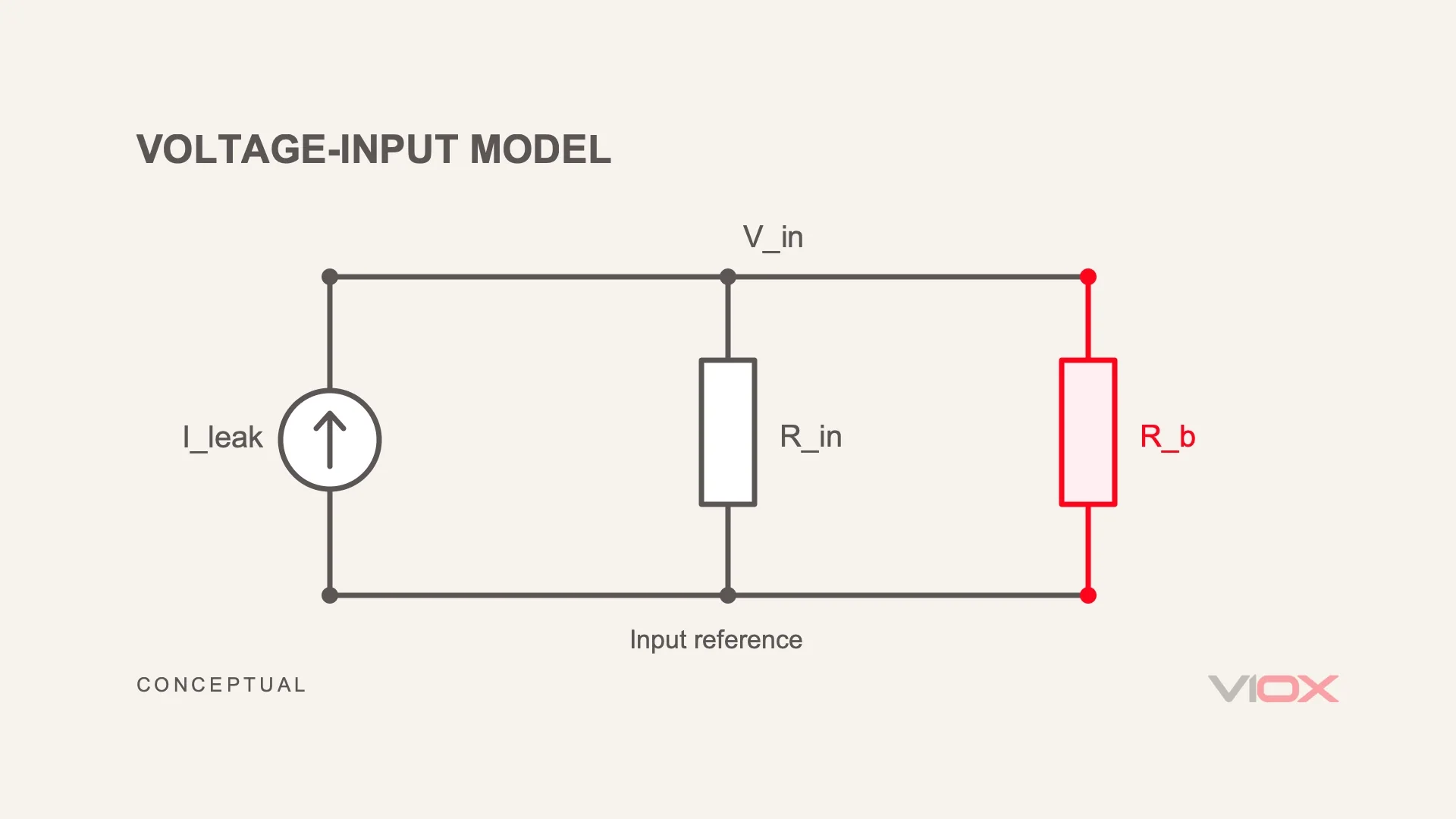
For an approximately current-source-like unwanted feed and linear resistive input:
V_in ≈ I_leak × (R_in || R_b)
Here || means parallel resistance. If the receiver only draws current from the node, ignoring that current gives the conservative OFF-state estimate:
R_b,max ≤ V_OFF,guaranteed / I_leak,max
Worked example: a DC control input, using assumed values. Suppose the source leaks up to 1 mA when OFF, and the timer is guaranteed inactive at 3 V or below. Use an active-high voltage input with a known reference that only draws current from the signal. Assume a parallel burden is allowed and the applied ON voltage is at most 24 V.
| الحساب | Result under those assumptions |
|---|---|
| Largest actual burden resistance from the OFF condition | 3 V / 1 mA = 3 kOhm |
| Evaluate a hypothetical actual resistance of 2.2 kOhm | Input voltage is no more than 1 mA × 2.2 kOhm = 2.2 V |
| Continuous resistor heating with the command ON | (24 V)^2 / 2,200 Ohm ≈ 0.262 W |
| Additional ON current demanded from the source | 24 V / 2,200 Ohm ≈ 10.9 mA |
The OFF voltage now fits the assumed limit. Next check the ON state: the source must supply the extra current while maintaining the receiver’s required ON voltage. The calculated heat is not the resistor’s nameplate wattage. Use maximum resistance, including tolerance and temperature, for the OFF check; use minimum resistance and maximum voltage for heating. Then select the component for its derating, voltage rating and enclosure conditions. This example supplies the calculation method, not VIOX product values. An AC or nonlinear input needs its own model. For AC, calculate continuous resistor heating from the worst-case RMS voltage across it; a higher voltage can make a burden thermally impractical. A properly matched interposing relay may be the better interface. A suppression RC network does a different job and can introduce another off-state current path.
A Properly Selected Interposing Relay
An electromechanical interface can receive the field command and provide an isolated contact to the timer. Check that its coil operates on a valid command and releases with the source OFF; a small coil can itself remain held by leakage. Account for the source’s load capability and the coil’s suppression arrangement. This route adds space and a service item but can give a dry-contact receiver the interface it expects.
A Receiver With Documented Off-State Compatibility
Changing the input variant may avoid extra components. Compare its guaranteed inactive/reset conditions with the source’s maximum OFF current, then confirm ON operation, polarity and timing function. Choose the interface before ordering, rather than trying to make an incompatible pair work during commissioning.
For a VIOX compatibility enquiry, send your control-circuit details: control voltage, exact timer variant, source or sensor datasheet, and the OFF-state observations. Include the input-reference pair and whether the problem is false initiation or failure to reset. This gives the selection discussion a clear starting point: a compatible receiver, an interposing contact or a calculated burden, as the circuit requires.
Correct the Wiring Route
For established cable coupling, separate command wiring from disturbing conductors and reduce unnecessary parallel exposure through an appropriate routing design. Repeat the original connected-input observations afterward. Routing addresses coupling, not inherent semiconductor leakage or an intentionally connected indicator path. Keep the final control drawing consistent with the installed remedy.
الأسئلة الشائعة
Can leakage current damage a timer relay?
Small residual currents within the input’s electrical limits usually cause logic or reset problems rather than direct damage. Applying an external voltage to the wrong interface is different and can damage it. Unexpected operation still needs investigation even when the timer itself is undamaged.
My timer works on the bench but misbehaves in the panel — why?
The bench may omit the semiconductor output, illuminated station or cable route providing the unwanted signal. Compare the installed input state with the isolated condition, including the control reference and reset sequence. A successful bench cycle does not reproduce every panel condition.
Is a burden resistor always the answer?
No. A compatible burden can help with an identified unwanted feed, but it also draws current and generates heat during a valid command. A dry-contact receiver may instead need an interposing contact, and cable coupling may be better addressed by routing. Select the remedy from the source and interface evidence.
Why does my meter show voltage on a disconnected trigger wire?
A high-impedance meter draws little current, so cable coupling or another weak source can produce a visible reading. A compatible loaded check may reduce it. The decisive comparison is whether the connected receiver reaches its required inactive state, not whether the unloaded conductor displays any voltage.
Are some timer relays immune to leakage current?
Input designs differ, but compatibility is conditional on the source and signal interface. Compare guaranteed ON/OFF requirements and reset behavior rather than assuming all electronic inputs are alike. No general brand label replaces that comparison.