
Direct Answer
Trip Class is a standardized rating system defined by IEC 60947-4-1 and NEMA standards that specifies the maximum time a motor protection device (thermal overload relay or motor protection circuit breaker) will take to trip and disconnect a motor when subjected to 600% (or 7.2×) of its rated current. The class number directly indicates the maximum trip time in seconds—Class 10 trips within 10 seconds, Class 20 within 20 seconds, and Class 30 within 30 seconds at this overload level. This classification ensures the protection device’s response time matches the motor’s thermal damage curve, preventing winding insulation failure while avoiding nuisance tripping during normal starting conditions.
Key Takeaways
- ✅ Trip Class Definition: The class number (5, 10, 10A, 20, 30) represents the maximum seconds to trip at 600% (NEMA) or 7.2× (IEC) of the relay’s current setting, ensuring protection aligns with motor thermal limits
- ✅ NEMA vs. IEC Standards: NEMA motors typically require Class 20 protection (designed for 1.15 service factor and robust thermal capacity), while IEC motors require Class 10 (application-rated with 1.0 service factor and tighter thermal margins)
- ✅ Selection Criteria: Choose Class 10 for quick-response applications (submersible pumps, hermetically sealed motors, VFD-driven motors), Class 20 for general-purpose NEMA motors, and Class 30 for high-inertia loads requiring extended acceleration time
- ✅ Thermal Damage Curve Matching: Trip class must align with the motor’s thermal withstand capability—mismatched protection can cause either premature failure (under-protection) or nuisance tripping (over-protection)
- ✅ Cold vs. Hot Start Behavior: Trip curves account for both cold-start conditions (motor at ambient temperature, longer trip times acceptable) and hot-restart scenarios (motor near operating temperature, faster protection required)
Understanding Trip Class: The Foundation of Motor Protection
What Trip Class Really Means
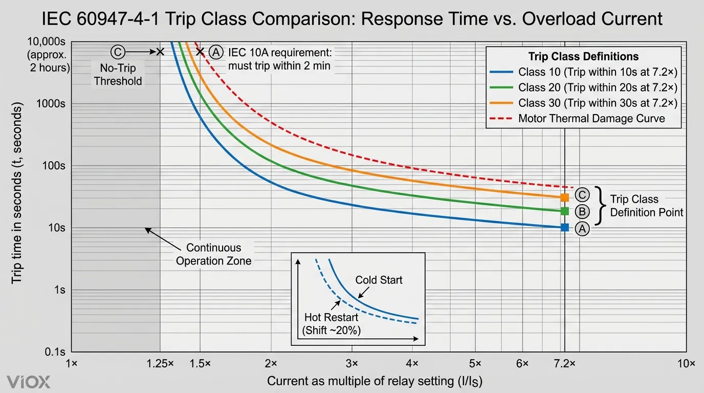
Trip Class is not simply a timing specification—it represents a carefully engineered correlation between the protection device’s response characteristics and the motor’s ability to withstand thermal stress. According to IEC 60947-4-1, the trip class defines two critical operating points that establish the complete protection curve:
Primary Definition Point (High Current):
- NEMA Standard: Trip within the class time (seconds) at 600% of the relay setting
- IEC Standard: Trip within the class time (seconds) at 7.2× the relay setting
Secondary Definition Point (Moderate Overload):
- At 125% of setting: Must NOT trip within 2 hours (cold start)
- At 150% of setting: Must trip within specific time based on class (IEC 10A: <2 minutes)
This dual-point definition creates an inverse-time characteristic curve that mirrors the motor’s thermal damage profile—the higher the overload, the faster the trip response.
The Physics Behind Trip Class Selection
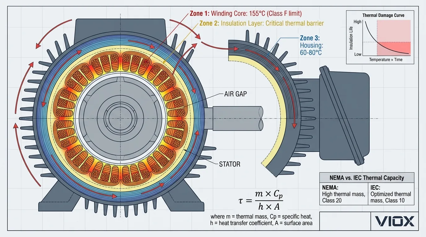
Motor winding insulation follows the “10-degree rule”—for every 10°C rise above rated temperature, insulation life is halved. During overload conditions, I2R heating in the windings increases exponentially with current. The trip class must ensure the protection device interrupts power before accumulated thermal energy (∫ I²·t dt) exceeds the motor’s thermal withstand capability.
Thermal time constant relationship:
τmotor > τrelay × Safety Margin
Where:
- τmotor = Motor thermal time constant (typically 30-60 minutes for enclosed motors)
- τrelay = Relay thermal time constant (varies by class)
- Safety Margin = Typically 1.2-1.5× to account for ambient variations
Standard Trip Classes: Complete Comparison
IEC 60947-4-1 Trip Classes
| Trip Class | Trip Time at 7.2× Ir | Typical Applications | Motor Type Compatibility |
|---|---|---|---|
| Class 5 | ≤5 seconds | Extremely fast protection for thermally sensitive motors | Hermetically sealed compressors, small submersible pumps |
| Class 10 | ≤10 seconds | Standard IEC motors, VFD applications | IEC Design N motors, artificially cooled motors, quick-response loads |
| Class 10A | ≤10 seconds at 7.2× ≤2 minutes at 1.5× |
Enhanced protection for hot-restart conditions | IEC motors with frequent start/stop cycles |
| Class 20 | ≤20 seconds | General-purpose NEMA motors | NEMA Design A/B motors with 1.15 SF, standard industrial applications |
| Class 30 | ≤30 seconds | High-inertia, extended acceleration loads | Mill-duty motors, crushers, large fans, centrifuges |
NEMA Trip Class Standards
NEMA standards align with IEC definitions but use 600% (6×) instead of 7.2× as the reference point. The practical difference is negligible—both systems produce equivalent protection curves.
Key NEMA-specific considerations:
- Class 20 Dominance: ~85% of NEMA motors are designed for Class 20 protection due to standardized 1.15 service factor and robust thermal design
- Locked-Rotor Time: NEMA MG-1 requires motors ≤500 HP to withstand locked-rotor current for ≥12 seconds at normal operating temperature, aligning with Class 20 protection
- Service Factor Interaction: Motors with 1.15 SF can handle 115% continuous overload, requiring trip curves that don’t interfere with this capability
Trip Class Selection Guide: Matching Protection to Application
Decision Matrix: Which Trip Class Do You Need?
| Motor Characteristic | Recommended Trip Class | Reasoning |
|---|---|---|
| NEMA Design A/B, 1.15 SF | Class 20 | Standard thermal capacity, 12-20 sec locked-rotor withstand |
| IEC Design N, 1.0 SF | Class 10 | Application-rated, tighter thermal margins, 10 sec locked-rotor withstand |
| Submersible pump motors | Class 10 or Class 5 | Liquid-cooled, rapid thermal rise when flow stops |
| VFD-driven motors | Class 10 | Reduced cooling at low speeds, no service factor when inverter-fed |
| High-inertia loads (>5 sec acceleration) | Class 30 | Extended starting time, prevents nuisance tripping |
| Frequent start/stop (>10 cycles/hour) | Class 10A | Hot-restart protection, 2-minute trip at 150% |
| Hermetically sealed motors | Class 5 or Class 10 | No external cooling, rapid temperature rise |
Critical Application Scenarios
Scenario 1: Centrifugal Pump with 15 HP NEMA Motor
Motor Specifications:
- Full-Load Current (FLA): 20A
- Service Factor: 1.15
- Locked-Rotor Current: 120A (6× FLA)
- Acceleration Time: 3 seconds
Analysis:
- Locked-rotor duration (3s) < Class 20 trip time (20s) → ✅ No nuisance tripping
- NEMA Design B motor → Class 20 standard
- 1.15 SF allows 23A continuous without trip
Selection: Class 20 thermal overload relay, set at 20A
Scenario 2: Submersible Well Pump with 5 HP Motor
Motor Specifications:
- Full-Load Current: 14A
- Service Factor: 1.0 (no SF for submersible)
- Locked-Rotor Current: 84A (6× FLA)
- Cooling: Water flow dependent
Analysis:
- Loss of water flow = rapid overheat (no external cooling)
- Requires fast protection to prevent burnout
- Manufacturer specifies Class 10 protection
Selection: Class 10 thermal overload relay, set at 14A
Scenario 3: Ball Mill with 200 HP Motor (High Inertia)
Motor Specifications:
- Full-Load Current: 240A
- Acceleration Time: 18 seconds
- Locked-Rotor Current: 1,440A (6× FLA)
- Load Type: High inertia, mechanical time constant >10s
Analysis:
- Acceleration time (18s) > Class 20 trip time (20s) → ⚠️ Marginal
- Acceleration time (18s) < Class 30 trip time (30s) → ✅ Safe margin
- High inertia requires extended starting allowance
Selection: Class 30 thermal overload relay, set at 240A
NEMA vs. IEC Motor Protection: Understanding the Fundamental Differences
Design Philosophy Comparison
| Aspect | NEMA Motors | IEC Motors |
|---|---|---|
| Design Approach | Conservative, over-designed for versatility | Application-specific, optimized for exact duty |
| Service Factor | Typically 1.15 (15% continuous overload capacity) | Typically 1.0 (no overload margin) |
| Thermal Capacity | High thermal mass, robust insulation systems | Optimized thermal design, minimal excess capacity |
| Standard Trip Class | Class 20 (20 seconds at 600% FLA) | Class 10 (10 seconds at 7.2× Ir) |
| Locked-Rotor Withstand | ≥12 seconds (NEMA MG-1 for ≤500 HP) | ~10 seconds (IEC 60034-12) |
| Insulation Class | Typically Class F (155°C) with Class B rise | Typically Class F with Class F rise |
| Starting Current | 6-7× FLA (NEMA Design B) | 5-8× In (IEC Design N) |
Why IEC Motors Require Faster Protection
IEC motors are designed with tighter thermal margins because they’re engineered for specific applications rather than general-purpose use. This “application rating” philosophy means:
- No Service Factor Buffer: An IEC motor rated for 10 kW delivers exactly 10 kW continuously—no 15% overload margin like NEMA 1.15 SF motors
- Optimized Cooling: Cooling systems are sized precisely for rated load, not over-designed
- Faster Thermal Response: Lower thermal mass means temperature rises more quickly during overload
- Global Efficiency Standards: IEC IE3/IE4 efficiency requirements drive tighter thermal designs
Practical implication: Using a Class 20 relay on an IEC motor can allow 10-20 seconds of damaging overload before tripping—potentially exceeding the motor’s 10-second thermal limit.
Cold Start vs. Hot Restart: The Hidden Complexity
Thermal State Impact on Trip Behavior
Trip class specifications are based on cold-start conditions—the motor and protection device are both at ambient temperature. However, real-world applications involve hot restarts after recent operation, fundamentally changing the protection dynamics.
Cold Start Characteristics:
- Motor windings at ambient temperature (~40°C)
- Full thermal capacity available
- Longer acceptable overload duration
- Trip curve follows published specifications
Hot Restart Characteristics:
- Motor windings near operating temperature (~120-155°C)
- Reduced thermal capacity (already partially “used”)
- Shorter safe overload duration
- Trip curve shifts left (faster tripping)
IEC Class 10A: The Hot-Restart Solution
IEC 60947-4-1 defines Class 10A specifically to address hot-restart protection inadequacies in standard Class 10/20 relays. The key difference:
| Condition | Standard Class 20 | IEC Class 10A |
|---|---|---|
| At 7.2× Ir (cold) | ≤20 seconds | ≤10 seconds |
| At 1.5× Ir (hot) | ~8 minutes | ≤2 minutes |
| Application | General purpose | Frequent start/stop, cyclic duty |
Why this matters: A motor running at full load reaches thermal equilibrium at ~120°C (Class F insulation). If it trips on overload and immediately restarts, a 150% overload can damage insulation within 2 minutes. Standard Class 20 relays may take 4-8 minutes to trip at this level, allowing thermal damage. Class 10A ensures protection within 2 minutes.
Motor Protection Circuit Breakers (MPCBs) vs. Thermal Overload Relays
Technology Comparison
| Feature | Thermal Overload Relay (TOR) | Motor Protection Circuit Breaker (MPCB) |
|---|---|---|
| Trip Mechanism | Bimetallic strip or eutectic alloy heating | Magnetic (instantaneous) + thermal (overload) |
| Trip Class Availability | Fixed (device-specific) or adjustable (electronic) | Fixed or adjustable (electronic trip units) |
| Short-Circuit Protection | ❌ No (requires separate breaker/fuse) | ✅ Yes (integrated magnetic trip) |
| Phase Loss Detection | ✅ Yes (inherent in 3-phase design) | ✅ Yes (electronic models) |
| Adjustability | Current setting adjustable, class usually fixed | Current + class adjustable (electronic models) |
| Reset Method | Manual or automatic | Manual (trip-free mechanism) |
| Typical Applications | Contactor-based starters, IEC applications | Stand-alone motor protection, NEMA/IEC hybrid |
| Standards | IEC 60947-4-1 (TOR), NEMA ICS 2 | IEC 60947-4-1 (MPSD), IEC 60947-2 (breaker) |
When to Use Each Technology
Choose Thermal Overload Relays When:
- Using contactor-based motor starters (standard IEC/NEMA configurations)
- Short-circuit protection provided by upstream circuit breaker or fuses
- Cost-sensitive applications
- Replacement/retrofit in existing contactor systems
Choose Motor Protection Circuit Breakers When:
- Integrated protection (overload + short-circuit) required in single device
- Space constraints (MPCB more compact than contactor + TOR + breaker)
- Direct-on-line (DOL) starting without contactor
- Frequent manual switching required (MPCB has built-in disconnect function)
Common Trip Class Selection Mistakes & Solutions
Mistake 1: Using Class 20 Protection on IEC Motors
Symptom: Motor fails prematurely, winding insulation breakdown, no trip occurred
Root Cause: IEC motor designed for Class 10 protection (10-second thermal limit) but protected by Class 20 relay (20-second trip time). The 10-second gap allows thermal damage.
Solution:
- Always verify motor manufacturer’s trip class requirement (check motor documentation or nameplate)
- When replacing NEMA motors with IEC equivalents, verify trip class compatibility
- Use electronic overload relays with adjustable trip class for flexibility
Mistake 2: Class 10 Relay Causing Nuisance Tripping on NEMA Motors
Symptom: Motor trips during normal starting, especially with high-inertia loads
Root Cause: NEMA Design B motor with 18-second acceleration time protected by Class 10 relay (10-second trip). Locked-rotor current (6× FLA) exceeds trip threshold before motor reaches full speed.
Solution:
- Calculate actual acceleration time: taccel = (J · ω) / (Tmotor – Tload)
- Ensure: taccel < 0.8 × ttrip class (20% safety margin)
- For this case: Use Class 20 or Class 30 relay
Mistake 3: Ignoring Hot-Restart Conditions
Symptom: Motor fails after multiple rapid start/stop cycles, even though cold-start protection is correct
Root Cause: Frequent cycling keeps motor at elevated temperature. Standard Class 20 relay allows 8 minutes at 150% overload (hot condition), but motor can only withstand 2 minutes.
Solution:
- For applications with >6 starts/hour: Use IEC Class 10A protection
- Implement minimum off-time delays (allow motor to cool between starts)
- Consider thermal model-based electronic relays that track motor temperature history
Mistake 4: Oversizing Relay Current Setting
Symptom: Motor runs hot continuously, eventual insulation failure, relay never trips
Root Cause: Relay set to 25A for a 20A motor (125% of FLA). Continuous 23A load (115% of motor FLA) never reaches relay trip threshold.
Solution:
- Set relay current to motor nameplate FLA (not service factor current)
- For 20A motor with 1.15 SF: Set relay to 20A, not 23A
- Relay trip curve at 125% (25A) will still allow service factor operation without nuisance tripping
Electronic vs. Thermal Trip Class Technology
Bimetallic/Eutectic Alloy Thermal Relays
How They Work:
- Current flows through heating element
- Bimetallic strip bends due to differential thermal expansion
- Mechanical linkage trips relay contacts when deflection threshold reached
Trip Class Characteristics:
- Fixed trip class (device-specific, cannot be changed)
- Ambient temperature compensation (bimetallic strip inherently compensates)
- Thermal memory (retains heat after trip, affects reset time)
- Trip curve accuracy: ±10-20% (mechanical tolerances)
Advantages:
- No external power required
- Immune to electrical noise/EMI
- Simple, proven technology
- Lower cost
Disadvantages:
- Fixed trip class (must stock multiple relay types)
- Slower response to rapid overloads
- Mechanical wear over time
- Limited diagnostic capability
Electronic Overload Relays
How They Work:
- Current transformers (CTs) measure motor current
- Microprocessor calculates thermal model: θ(t) = θ0 + ∫ [(I2 – Irated2) / τ] dt
- Trips when calculated temperature exceeds threshold
Trip Class Characteristics:
- Selectable trip class (Class 5, 10, 10A, 15, 20, 30 via DIP switch or software)
- Digital thermal model (tracks motor temperature continuously)
- Hot-restart compensation (remembers thermal state after power loss)
- Trip curve accuracy: ±5% (digital precision)
Advantages:
- Single device covers multiple trip classes (reduces inventory)
- Advanced diagnostics (current imbalance, phase loss, ground fault)
- Communication capability (Modbus, Profibus, EtherNet/IP)
- Programmable features (alarm thresholds, trip delay)
Disadvantages:
- Requires control power supply
- More complex (higher initial cost)
- Susceptible to electrical noise (requires proper grounding)
- Firmware updates may be needed
Trip Class and Motor Coordination: Type 1 vs. Type 2
IEC 60947-4-1 Coordination Types
Motor protection systems must coordinate with short-circuit protective devices (fuses or circuit breakers) to ensure safe fault interruption. Trip class affects this coordination:
Type 1 Coordination:
- Under short-circuit conditions, contactor or starter may sustain damage
- No danger to persons or installation
- Repair or replacement may be required before restart
- Trip class impact: Minimal—focuses on short-circuit protection, not overload
Type 2 Coordination:
- Under short-circuit conditions, no damage to contactor or starter (except possible contact welding)
- No danger to persons or installation
- Equipment ready for service after fault cleared
- Trip class impact: Significant—overload relay must trip before contactor contacts weld
Coordination example:
| Motor FLA | Trip Class | Upstream Fuse | Coordination Type | Max Fault Current |
|---|---|---|---|---|
| 32A | Class 10 | 63A gG fuse | Type 2 | 50 kA |
| 32A | Class 20 | 63A gG fuse | Type 2 | 50 kA |
| 32A | Class 30 | 80A gG fuse | Type 1 | 50 kA |
Key insight: Slower trip classes (Class 30) may require larger fuses to achieve coordination, potentially compromising Type 2 performance. Manufacturers provide coordination tables specifying maximum fuse sizes for each trip class.
Internal Links & Related Resources
For comprehensive understanding of motor protection systems and related electrical components, explore these VIOX technical guides:
- What Are Thermal Overload Relays: Complete Guide to Motor Protection Devices – Deep dive into thermal overload relay technology, types, and selection criteria
- NEMA Class 20 vs. IEC Class 10 Overload Relay Guide – Detailed comparison of NEMA and IEC motor protection standards
- Contactor vs. Motor Starter: Understanding the Key Differences – Learn how contactors and overload relays work together in motor control
- How to Select Contactors and Circuit Breakers Based on Motor Power – Practical sizing guide for complete motor protection systems
- Electrical Standards for Contactors: Understanding AC1, AC2, AC3, AC4 Utilization Categories – Comprehensive guide to IEC 60947-4-1 utilization categories
FAQ: Trip Class Selection & Application
Q1: Can I use a Class 10 overload relay on a NEMA motor rated for Class 20?
A: Technically yes, but not recommended for most applications. While a Class 10 relay provides faster protection (potentially beneficial), it may cause nuisance tripping during normal starting, especially for high-inertia loads or motors with acceleration times >8 seconds. The NEMA motor is designed to safely handle the thermal stress associated with Class 20 protection (20-second withstand at 600% FLA), so using Class 10 doesn’t provide additional safety margin—it just increases the risk of unwanted trips. Exception: If the motor manufacturer specifically recommends Class 10 (e.g., for VFD operation or special duty cycles), follow their guidance.
Q2: How do I determine the correct trip class if the motor nameplate doesn’t specify it?
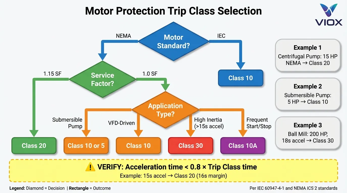
A: Follow this decision tree:
- Check motor origin: NEMA motors (North American) → Class 20; IEC motors (European/Asian) → Class 10
- Check service factor: 1.15 SF → Class 20; 1.0 SF → Class 10
- Check application type:
- Submersible pumps → Class 10 or Class 5
- VFD-driven motors → Class 10
- High-inertia loads (acceleration >15s) → Class 30
- General industrial → Class 20
- Consult manufacturer: When in doubt, contact the motor manufacturer with the motor serial number—they can provide the recommended trip class based on design specifications.
Q3: What happens if I use the wrong trip class?
A: Two failure modes:
- Under-protection (Class too slow): Motor experiences thermal damage before relay trips. Example: Class 20 relay on Class 10 motor allows 10-20 seconds of damaging overload. Result: Shortened motor life, insulation breakdown, eventual failure.
- Over-protection (Class too fast): Relay trips during normal operation, causing nuisance shutdowns. Example: Class 10 relay on high-inertia load with 18-second acceleration. Result: Motor never reaches full speed, production downtime, frustrated operators who may bypass protection (dangerous).
Q4: Do electronic overload relays provide better protection than thermal relays?
A: Not necessarily “better,” but more flexible and precise. Electronic relays offer:
- Adjustable trip class (one device = multiple applications)
- Higher accuracy (±5% vs. ±15% for thermal)
- Advanced diagnostics (current imbalance, ground fault, thermal state)
- Communication (remote monitoring, predictive maintenance)
However, thermal relays have advantages:
- No external power required (self-powered by motor current)
- Immune to electrical noise (important in harsh EMI environments)
- Lower cost (for simple, fixed applications)
Recommendation: Use electronic relays for critical applications, variable loads, or where diagnostics/communication are needed. Use thermal relays for cost-sensitive, fixed-duty applications where simplicity is valued.
Q5: How does ambient temperature affect trip class performance?
A: Ambient temperature directly impacts trip time because both the motor and protection device are affected:
Motor side:
- Higher ambient → Less thermal capacity available → Faster temperature rise
- Standard rating: 40°C ambient (IEC/NEMA)
- Derating required above 40°C (typically 1% per °C above 40°C)
Relay side:
- Bimetallic relays: Inherently compensate (bimetallic strip responds to ambient + load heating)
- Electronic relays: Require ambient compensation setting (many have built-in temperature sensors)
Example: A motor in a 50°C ambient (10°C above standard) has ~10% less thermal capacity. The relay must be set 10% lower (18A instead of 20A for a 20A motor) OR the motor must be derated to 18A continuous operation. Trip class remains the same, but the current threshold changes.
Conclusion
Trip Class is far more than a simple timing specification—it represents the critical link between motor thermal characteristics and protection device response. Understanding the nuances of Class 5, 10, 10A, 20, and 30 protection enables engineers to design motor control systems that prevent both catastrophic failures and costly nuisance tripping.
Key design principles to remember:
- Match protection to motor design: NEMA motors (Class 20) and IEC motors (Class 10) have fundamentally different thermal capacities—mismatched protection compromises safety or reliability
- Consider real-world duty cycles: Cold-start specifications don’t tell the whole story—hot-restart conditions (frequent cycling) may require faster protection (Class 10A)
- Verify acceleration time compatibility: Calculate actual motor acceleration time and ensure it’s less than 80% of the trip class time to prevent nuisance tripping
- Leverage modern technology: Electronic overload relays with adjustable trip classes provide flexibility, diagnostics, and precision that fixed thermal relays cannot match
- Coordinate with upstream protection: Trip class selection affects Type 1/Type 2 coordination with fuses and circuit breakers—consult manufacturer coordination tables
As motor efficiency standards tighten globally (IEC IE4, IE5 on the horizon), thermal margins continue to shrink, making proper trip class selection more critical than ever. The trend toward IEC-style application-rated motors—even in North American markets—means engineers must understand both NEMA and IEC protection philosophies to specify systems that deliver long-term reliability.
About VIOX Electric: VIOX Electric is a leading B2B manufacturer of electrical equipment, specializing in motor protection circuit breakers (MPCBs), thermal overload relays, contactors, and comprehensive motor control solutions for industrial and commercial applications. Our engineering team provides technical support for motor protection system design, trip class selection, and coordination studies. Contact us for application-specific guidance and product selection assistance.
