Bu sayfada
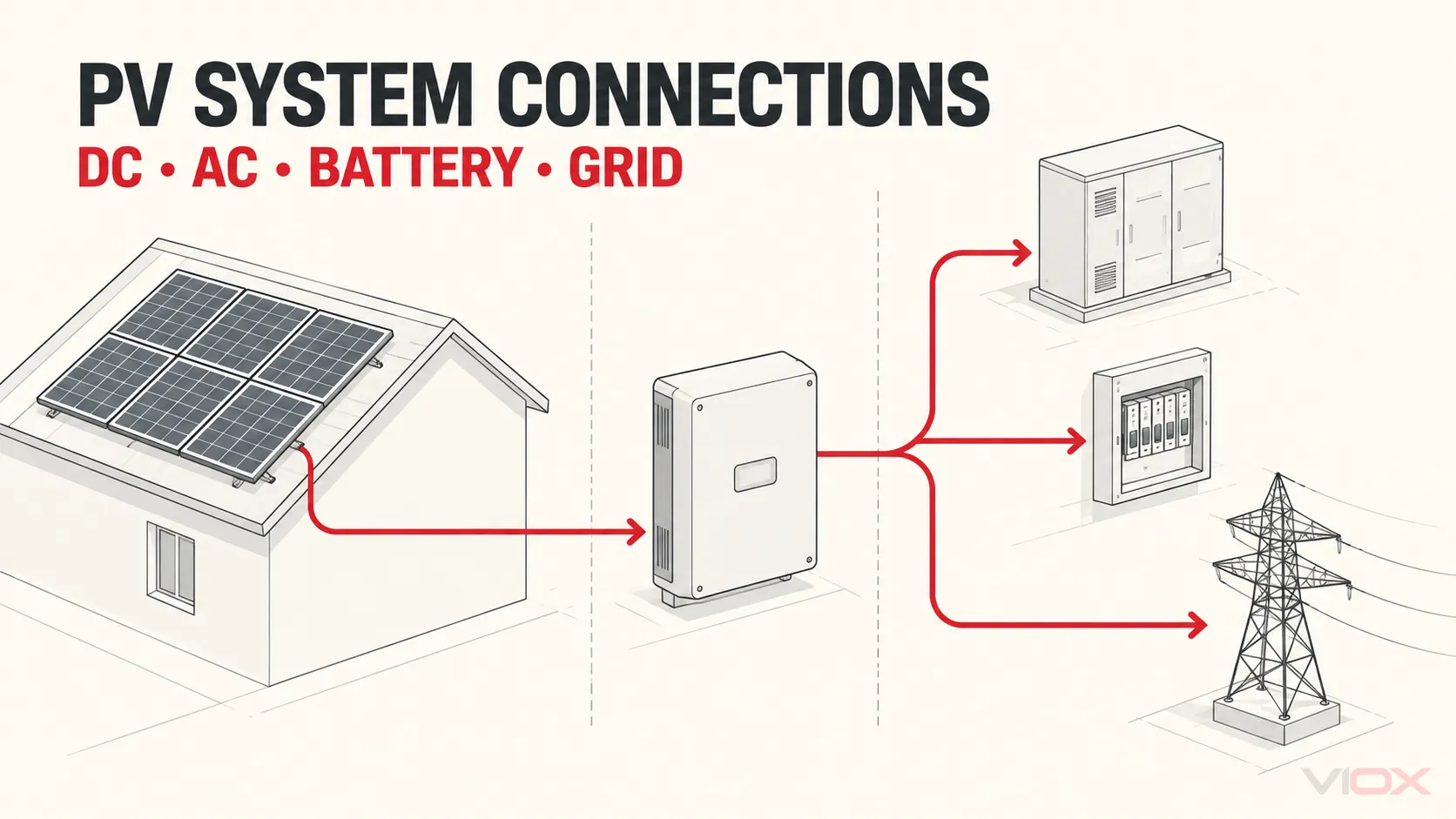
Bir güneş fotovoltaik (PV) sisteminin tek bir evrensel bağlantı şeması yoktur. Bir dizi evirici (string-inverter) sistemi, dizi seviyesindeki doğru akımı (DC) merkezi bir dönüştürme noktasına taşırken, bir mikro evirici sistemi her modülde alternatif akıma (AC) dönüşür. Hibrit ve depolama sistemleri bir batarya barası, başka bir dönüştürücü veya korumalı bir yedek yük sınırı ekler. Bu nedenle doğru tasarım, genel bir parça listesiyle değil; mimari, ekipman sınırları, topraklama ve nötr düzenlemesi ve amaçlanan çalışma modu ile başlar.
Önemli: Bu makaledeki şemalar kavramsal sistem haritalarıdır, kurulum çizimleri değildir. Gerçek iletken boyutlandırması, aşırı akım koruması, yalıtım, topraklama, hızlı kapatma, artık akım koruması, etiketleme ve ara bağlantı gereksinimleri, ekipman talimatlarına ve sistemin kurulduğu yerde uygulanan kurallara bağlıdır. PV iletkenleri, dizi aydınlatıldığı sürece enerjili kalabilir. Tasarım, kurulum, test ve devreye alma işlemleri yetkili personelin sorumluluğundadır.
Bileşenlerle Değil, Mimariyle Başlayın
“Güneş panellerini invertöre bağlayın” ifadesi birçok kararı gizler. DC nerede AC'ye dönüşür? Modüller seri, paralel veya her ikisi birden mi bağlanmıştır? Bir batarya DC baraya mı yoksa ayrı bir invertör aracılığıyla AC elektrik sistemine mi bağlıdır? Kurulum şebeke kesintisi sırasında duruyor mu, yoksa seçili yükler için kasıtlı bir ada oluşturabiliyor mu?
Bu kararlar, hangi iletkenlerin DC taşıyacağını, hangi ekipmanın her bir kaynağı izole edebileceğini ve koruma ile anahtarlama fonksiyonlarının nerede gerekli olabileceğini belirler.
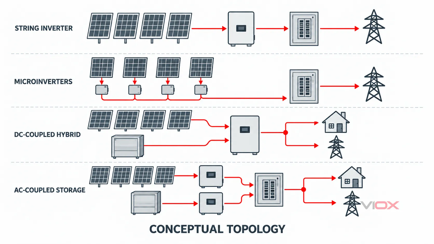
| Sistem mimarisi | Ana güç yolu | DC'nin AC'ye dönüştüğü yer | Akü yolu | Tipik kesinti davranışı |
|---|---|---|---|---|
| Dizi evirici, şebekeye bağlı | Modüller → diziler → isteğe bağlı birleştirici → evirici → AC dağıtımı/şebeke | Dizi veya merkezi eviricide | Ayrı olarak eklenmediği sürece yok | Şebeke kullanılamadığında normalde kapanır |
| Mikroinverter, şebekeye bağlı | Modül → mikroinverter → AC branşman → AC dağıtım/şebeke | Her modülde | Genellikle ayrı, eğer takılıysa | Uyumlu bir ada modu sistemi sağlanmadığı sürece normalde kapanır |
| DC bağlantılı hibrit | Modüller/diziler → hibrit inverter DC girişi; batarya → hibrit inverter batarya portu | Hibrit inverterin içinde | DC kuplajlı | Sadece sistem ada modu için tasarlandığında ve yapılandırıldığında belirlenen yedek yükleri besleyebilir |
| AC kuplajlı depolama | PV inverter → AC bara; batarya inverteri → aynı kontrollü AC sistemi | Ayrı PV ve batarya inverterlerinde | Çift yönlü bir inverter üzerinden AC kuplajlı | Kontrol sistemine, izolasyon cihazına ve şebeke oluşturma kapasitesine bağlıdır |
Bu tablo bir mimari seçicidir; her kurulumun listelenen tüm bileşenlere ihtiyaç duyduğu bir kural değildir.
PV Bağlantılarını Karmaşık Hale Getiren Sınırlar
Çoğu hata, birkaç farklı sınırın aynıymış gibi ele alınmasıyla başlar.
1. Üretim sınırı
PV modülleri, üzerlerine yeterli ışık ulaştığında DC üretir. Şebeke tarafındaki bir devre kesici güneş ışığını kapatmaz. Bu nedenle, bir invertörün AC tarafını açmak, tek başına PV dizi iletkenlerinin enerjisiz olduğunu kanıtlamaz.
2. Toplulaştırma sınırı
Seri bağlanan modüller bir dizi oluşturur. Seri bağlantı voltajı yükseltir; modül akımlarını paralel bağlantıda olduğu gibi toplamaz. Diziler paralellendiğinde akımları birleşir. Bu değişim; kablo kapasitesini, ters akım maruziyetini, aşırı akım koruma kararlarını ve bir birleştirici kutusunun (combiner box) gerekli olup olmadığını etkiler.
Maksimum dizi voltajı, projenin minimum sıcaklık koşulları altında invertör veya güç dönüştürme ekipmanı limiti ile karşılaştırılarak kontrol edilmelidir. Akım ile ilgili tasarım girdileri; paralel dizi sayısını, modül verilerini, çevresel koşulları ve geçerli tasarım yöntemini hesaba katmalıdır. Bu hesaplamalar kopyalanmış genel bir şemada değil, proje tasarımında yer almalıdır.
3. Dönüştürme sınırı
Bir evirici, yalnızca iki kablo seti arasındaki bir bağlantı elemanı değildir. DC'nin AC'ye dönüştürüldüğü ve çalışma sınırları, izleme, kontrol ve şebeke etkileşimi işlevlerinin buluştuğu sınırdır.
Bu ABD Enerji Bakanlığı bir dizinin çıkışını merkezi bir noktada dönüştüren dizi eviricileri, bireysel modüllere kurulan mikro eviricilerden ayırır. Bu konum değişikliği, DC'den AC'ye geçiş sınırını kaydırır ve dolayısıyla tüm akış yönündeki yerleşimi değiştirir.
4. Şebeke bağlantı sınırı
Şebekeye bağlı bir evirici, elektrik sistemi ile uyumlu çalışmalıdır. Geleneksel bir şebeke takip eden PV sistemi, şebeke olmadığında şebeke bağlantısını enerjisiz bırakacak şekilde düzenlenir. Bu nedenle güneş panelleri tek başlarına, bir kesinti sırasında otomatik olarak yedek güç sağlamazlar.
Yedek çalışma; bilinçli olarak tasarlanmış bir ada modu sınırı, uyumlu kontrol ekipmanı ve ada modundaki yükleri destekleyebilecek bir kaynak gerektirir. Sisteme bağlı olarak bu; hibrit veya şebeke oluşturan bir evirici, batarya depolama, transfer veya izolasyon ekipmanı, bir yedek dağıtım panosu ve tanımlanmış bir nötr ve topraklama düzeni içerebilir.
5. Yedek yük sınırı
“Tüm bina” ve “temel yükler” farklı tasarımlardır. Bir hibrit evirici, ayrı bir temel yükler panosunu besleyen özel bir yedek çıkışa sahip olabilir. Başka bir sistem, harici bir transfer düzeni kullanabilir. Bu sınırın değerleri ve davranışı; yük talebi, evirici kapasitesi, mevcut kısa devre akımı, anahtarlama sırası ve yerel kurulum kuralları ile koordine edilmelidir.
Mimari 1: Şebekeye Bağlı String İnverter
Bir dizi evirici mimarisinde, modüller bir veya daha fazla DC dizisi oluşturmak üzere seri bağlanır. Diziler doğrudan ayrı evirici girişlerine bağlanabilir veya birkaç dizi önce uygun bir toplama ekipmanı aracılığıyla bir araya getirilebilir.
Kavramsal yol şöyledir:
PV modülleri → DC dizileri → isteğe bağlı birleştirici/koruma → DC izolasyonu → dizi evirici → AC koruma/izolasyon → dağıtım panosu veya bağlantı noktası
Bir birleştirici kutusu otomatik olarak gerekli değildir. Uygun sayıda bağımsız girişe sahip bir evirici, dizileri doğrudan kabul edebilir. Daha büyük diziler veya birkaç diziyi paralel bağlayan tasarımlar, iletkenleri düzenlemek ve belirtilen koruma ve izolasyon işlevlerini barındırmak için bir birleştirici kullanabilir.
Temel mühendislik soruları şunlardır:
- Maksimum düzeltilmiş dizi açık devre gerilimi, ilgili tüm DC giriş sınırlarının altında kalıyor mu?
- Her dizi uygun bir maksimum güç noktası izleyici (MPPT) girişine bağlı mı?
- Kaç dizi paralel bağlanmıştır ve arızalı bir dizi ne kadar ters akım alabilir?
- Hangi DC ve AC izolasyon işlevleri gereklidir ve bunlara nerede erişilebilir olmalıdır?
- İnvertere hangi koruma entegre edilmiştir ve harici olarak ne sağlanmalıdır?
Detaylı toplama yolu için VIOX kullanın Güneş enerjisi birleştirici kutu (solar combiner box) bağlantı şeması ve bu sistem haritasını bir tesisat kablolaması olarak ele almayın.
Mimari 2: Modül Seviyesi Mikro İnverterler
Mikroinverterlerde her bir modül veya bazen küçük bir modül grubu, yerel bir inverteri besler. Bu nedenle çatı tarafındaki toplama devresi, merkezi bir inverteri besleyen uzun ve yüksek gerilimli bir DC dizisi yerine, her dönüşüm noktasından sonra AC'dir.
Kavramsal yol şöyledir:
PV modülü → mikroinverter → AC branşman/ana hat kablosu → AC yalıtım ve koruma → dağıtım panosu veya bağlantı noktası
Bu mimari, dönüşümün konumunu değiştirir ancak sistem tasarımı ihtiyacını ortadan kaldırmaz. AC branşmanının akım, gerilim, koruma cihazı, iletken, konnektör ve ekipman sayısı limitleri vardır. Modül seviyesindeki ekipmanlar ayrıca modülle ve onaylanmış sistem düzeniyle uyumlu olmalıdır.
Dizi inverter koruma yerleşimini bir mikroinverter şemasına kopyalamayın. Paralel diziler için tasarlanmış bir DC birleştirici, bir AC branşman toplama noktasıyla aynı işi yapmaz.
Mimari 3: DC Bağlantılı Hibrit İnverter ve Batarya
DC kuplajlı bir hibrit sistem, PV ve batarya enerjisini tek bir hibrit güç dönüşüm platformunda birleştirir. PV dizisi belirlenmiş PV DC girişlerine bağlanırken, batarya inverter üreticisi tarafından tanımlanan batarya arayüzü üzerinden bağlanır.
Kavramsal yollar şunlardır:
PV dizisi → hibrit evirici PV girişi → AC yükleri/şebeke
Batarya → batarya koruması/izolasyonu → hibrit evirici batarya portu → AC yükleri/şebeke
Batarya başka bir PV dizisi değildir. Gerilim davranışı, olası akımı, koruması, haberleşmesi, izolasyonu ve hata tepkisi farklıdır. Sadece onaylı batarya-evirici kombinasyonları ve belgelenmiş bağlantı yöntemleri kullanılmalıdır.
Yedekleme çalışması gerekiyorsa, şema ayrıca şunları tanımlamalıdır:
- şebeke girişi;
- normal AC bağlantısı;
- eviricinin yedek veya acil durum çıkışı;
- bu çıkışta izin verilen yükler;
- şebekenin istenmeyen şekilde enerjilenmesini önleyen cihaz;
- hem şebekeye bağlı hem de ada modlarında nötr ve koruma iletkeni düzenlemesi.
VIOX, bu anahtarlama sınırlarını kendi güneş enerjisi ve evirici sistemleri için otomatik transfer şalteri kılavuzunda ayrı ayrı açıklamaktadır. Evirici kılavuzu ve geçerli kurulum kuralları, fiili bağlantılar için temel referans olmaya devam eder.
Mimari 4: AC Bağlantılı Depolama veya Şebekeden Bağımsız Besleme
AC kuplajlı bir sistemde, PV evirici ve batarya evirici, kontrollü bir AC sistemi üzerinden bağlanan ayrı güç dönüştürme cihazlarıdır. Güneş enerjisi, AC'ye dönüştürüldükten sonra yükleri besleyebilir veya bataryayı şarj edebilir; batarya evirici daha sonra depolanan DC enerjisini tekrar AC'ye dönüştürür.
Kavramsal yollar şunlardır:
PV dizisi → PV evirici → kontrollü AC barası
Batarya ↔︎ çift yönlü batarya eviricisi ↔︎ kontrollü AC barası
Şebeke veya jeneratör ↔︎ transfer/ara bağlantı sınırı ↔︎ kontrollü AC barası
Bu mimari bazen mevcut bir PV kurulumuna depolama eklemek için kullanılır, ancak uyumluluk sadece bir AC bağlantısının varlığından çıkarılamaz. Kontrol sistemi şarj, dışa aktarım, ada oluşumunu önleme, transfer ve ada modunda çalışmayı koordine etmelidir. Bir kesinti sırasında, batarya eviricisi, şebeke takip eden bir PV eviricisinin ihtiyaç duyduğu gerilim ve frekans referansını oluşturmak zorunda kalabilir. Bu işlemin desteklenip desteklenmediği ekipmana özeldir.
Şebekeden bağımsız bir sistem basitleştirilmiş bir çizimde benzer görünebilir ancak farklı bir işletim hedefine sahiptir: bir şebeke kaynağı olmaksızın üretim, depolama ve yükü sürekli olarak dengelemelidir. Bu nedenle jeneratör entegrasyonu, yük atma, siyah başlatma davranışı ve batarya durum sınırları birincil tasarım girdileri haline gelebilir.
Koruma Fonksiyonlarının Yeri
Koruma, başka bir sistemden parça listesi kopyalanarak değil, elektrik bölgesi ve tehlikeye göre atanmalıdır.
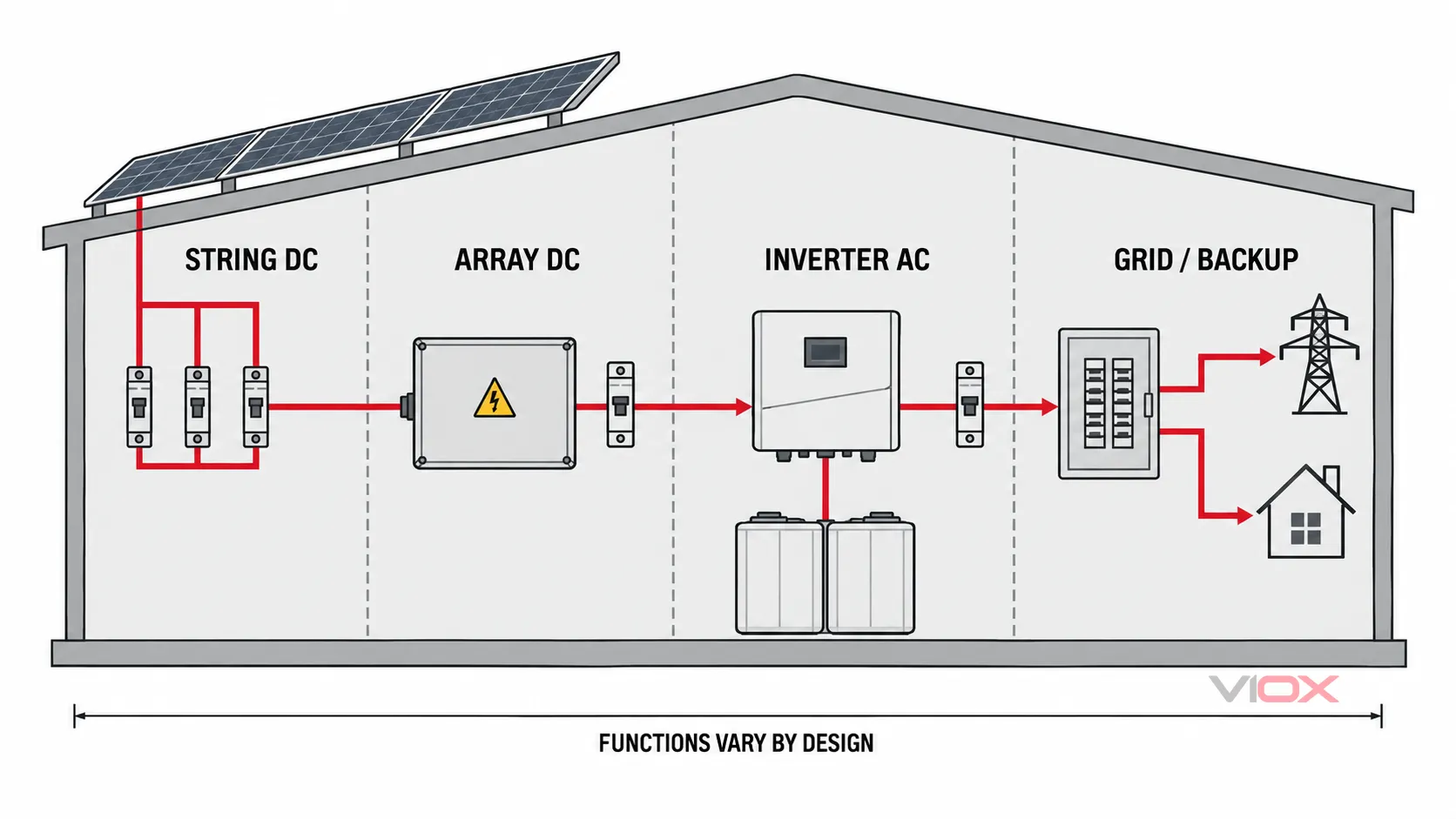
| Elektrik bölgesi | Tasarım sorusu | Değerlendirilecek olası fonksiyonlar |
|---|---|---|
| Modül ve dizi DC | Başka bir kaynak arızaya zarar verici akım gönderebilir mi? Devre güvenli bir şekilde izole edilebilir mi? | Gerektiğinde dizi aşırı akım koruması, DC konnektörleri, kablo koruması, izolasyon, uygulanabilir durumlarda ark hatası veya hızlı kapatma fonksiyonları |
| Birleşik dizi DC | İnverter besleyicisine hangi akım ve gerilim ulaşıyor? | Gerektiğinde birleştirici, sigorta veya devre kesici, DC SPD, izleme, ana DC izolasyonu |
| İnverter AC çıkışı | Dönüştürücü, AC sistemine nasıl bağlanıyor ve sistemden nasıl ayrılıyor? | İnverter ve kurulum kuralları tarafından belirtildiği şekilde AC aşırı akım koruması, yalıtım, aşırı gerilim koruması ve artık akım önlemleri |
| Akü devresi | Akü gerilimi, muhtemel akım ve onaylı arayüz nedir? | Akü nominal koruması ve yalıtımı, akü yönetimi koordinasyonu, acil durum kontrolleri |
| Şebeke/yedekleme sınırı | Kaynaklar paralel veya adalanma modunda çalışabilir mi ve nelerin anahtarlanması gerekir? | Ara bağlantı koruması, transfer/adalanma fonksiyonu, kaynak koordinasyonu, yedek yük dağıtımı |
“Olası” ifadesi kasıtlıdır. Gerekli cihazlar, değerler, kutuplar, konumlar ve koordinasyon; topolojiye, ekipman talimatlarına, kurulum ortamına ve geçerli yönetmeliklere bağlıdır. DC koruma fonksiyonlarına dair odaklanmış bir açıklama için bkz. PV DC koruması: MCB'ler, sigortalar ve SPD'ler ile RCD'lerin karşılaştırılması.
Neden Genel Bir Güneş Enerjisi Kablolama Şeması Yetersiz Kalır
Genel bir çizim, tasarımı değiştiren en az bir değişkeni genellikle ihmal eder.
Sıcaklık düzeltmeli DC gerilimini göz ardı eder
PV modül açık devre gerilimi sıcaklıkla değişir. İlgili tasarım kontrolü, sadece tek bir uygun test koşulu altında etiket geriliminin modül sayısıyla çarpılması değildir.
Tüm evirici girişlerini birbirinin yerine kullanılabilir olarak ele alır
Girişler ayrı MPPT kanallarına ait olabilir ve farklı izin verilen dizi düzenlemelerine sahip olabilir. Farklı yönelim, modül tipi veya elektriksel özelliklere sahip paralel dizilerin bir girişi doğru şekilde paylaşacağı varsayılamaz.
İzolasyonu aşırı akım koruması ile karıştırır
Bir ayırıcı, sigorta, devre kesici ve aşırı gerilim koruyucu cihaz farklı sorunları çözer. Tam ürün bu işlev için derecelendirilmedikçe ve belgelenmedikçe, bir cihaza başka bir işlev atfedilmemelidir. VIOX ayrı bir güneş enerjisi bağlantı kesme anahtarı seçim kılavuzu ve DC SPD seçim kılavuzu bu kararlar için.
Nötr ve topraklama düzenini belirtilmemiş halde bırakır
Nötr, koruma iletkenleri, açıkta kalan iletken kısımlar, dizi topraklaması ve kaynak referansının ele alınışı, normal çalışma ile ada modu çalışması arasında değişiklik gösterebilir. Bu detaylar, “şebeke” olarak etiketlenmiş bir hattan çıkarılamaz.”
Bataryanın yedekleme anlamına geldiğini varsayar
Depolama; elektrik kesintisi sırasında yükleri beslemeden, öz tüketim, talep yönetimi veya ihracat kontrolü için kurulabilir. Yedekleme özelliği açıkça tasarlanmalı, derecelendirilmeli ve devreye alınmalıdır.
Entegre fonksiyonları gizler
Modern eviriciler; DC anahtarları, dizi girişleri, SPD'ler, artık akım izleme veya transfer fonksiyonlarını içerebilir. Harici bir cihazın gerekli olup olmadığı, tam ekipman dokümantasyonuna ve kurulum kurallarına bağlıdır. Evirici spesifikasyonunu kontrol etmeden sembolleri saymak, mükerrerliğe veya eksik bir fonksiyona yol açabilir.
Nihai Bağlantıları Çizmeden Önce Gerekli Bilgiler
Detaylı bir kablolama şeması seçmeden veya ekipman talep etmeden önce bu kontrol listesini kullanın. Eğer bir öğe bilinmiyorsa, sistem mimarisi bir kurulum çizimine dönüşmeye hazır değildir.
PV dizisi
- Modül modeli, açık devre gerilimi, kısa devre akımı, maksimum güç değerleri ve sıcaklık katsayıları
- Dizi başına modül sayısı, dizi sayısı, yönelimler ve gölgeleme grupları
- Tasarım için kullanılan minimum ve maksimum saha sıcaklıkları
- Kablo güzergahları, uzunlukları, kurulum yöntemi ve çevresel maruziyet
İnverter veya güç dönüştürme ekipmanı
- Tam model ve kurulum kılavuzu
- Maksimum DC gerilimi, MPPT gerilim aralığı, giriş akımı limitleri ve izin verilen dizi düzenlemeleri
- AC gerilimi, faz konfigürasyonu, nominal çıkış akımı ve şebeke kodu ayarları
- Entegre izolasyon, koruma, izleme, hızlı kapatma veya artık akım fonksiyonları
Batarya ve yedek güç çalışması
- Batarya kimyası, nominal ve çalışma gerilimi aralığı, muhtemel akım ve onaylı inverter uyumluluğu
- DC-kuplajlı veya AC-kuplajlı düzenleme
- Yedek güç hedefi: yok, seçili yükler veya tüm tesisat
- Sürekli ve ani yük gereksinimleri
- Şebekeye bağlı, adalanmış ve geri yükleme işletim sırası
Kurulum ve ara bağlantı
- Topraklama sistemi ve nötr düzenlemesi
- Bağlantı noktası ve mevcut hata akımı bilgisi
- Uygulanabilir kurulum kodu, şebeke kuralları ve yetkili makam gereklilikleri
- Gerekli yalıtım, etiketleme, acil durum kontrolleri, itfaiye hizmeti hükümleri ve erişim
- Muhafazalar, konnektörler, SPD'ler, anahtarlar ve koruyucu cihazlar için çevresel koşullar
Doğrulama ve teslim
- Onaylı tek hat şeması ve ekipman listeleri
- Denetim ve devreye alma planı
- İlgili kuralların gerektirdiği polarite, yalıtım, koruma cihazı, işlevsel ve çalışma modu kontrolleri
- Nihai etiketler, kapatma talimatları, test sonuçları ve kullanıcı dokümantasyonu
IEC 60364-7-712:2025 modüllerden daha geniş tesisata bağlantıya kadar olan PV elektrik tesisatlarını ele alır ve artık enerji depolama hususlarını da içerir. IEC 62548-1:2023+A1:2025 DC kablolama, koruma, anahtarlama ve topraklama hükümleri dahil olmak üzere PV dizisi tasarımını kapsar. IEC 62446-1:2016+A1:2018 şebekeye bağlı sistemler için dokümantasyon, devreye alma testleri ve denetimi ele alır. Bu standartlar mühendislik görevinin farklı bölümlerini tanımlar; hiçbiri genel bir internet şeması ile değiştirilemez.
VIOX PV Kılavuzları için Pratik Bir Okuma Sırası
Mimari kesinleştiğinde, bir sonraki karardan sorumlu uzman sayfasına devam edin:
- Kullanın PV birleştirici kutu kılavuzu toplama ekipmanına ihtiyaç duyulup duyulmadığına ve ne işe yaradığına karar vermek için.
- Kullanın Güneş enerjisi birleştirici kutu (solar combiner box) bağlantı şeması geleneksel bir birleştirici düzeninin dahili işlevsel yolunu anlamak için.
- Kullanın PV sigorta ve ayırıcı boyutlandırma kılavuzu yalnızca belirtilen kod çerçevesi projeyle eşleştiğinde.
- Kullanın solar SPD seçim kılavuzu DC SPD tipini, sürekli çalışma gerilimini ve yerleşimini değerlendirmek için.
- Kullanın solar ayırıcı seçim kılavuzu dizi, birleştirici ve evirici yalıtım görevlerini ayırt etmek için.
- Kullanın güneş enerjisi ve inverter transfer kılavuzu şebeke, inverter, jeneratör ve yedek yük anahtarlamasının koordine edilmesi gerektiğinde.
Güvenilir sıra şöyledir mimari → elektriksel sınırlar → ekipman değerleri → koruma koordinasyonu → detaylı şema → doğrulama. Kopyalanmış bir kablolama şemasıyla başlamak bu sırayı tersine çevirir ve PV bağlantılarının karmaşık hale gelmesinin ana nedenidir.
Bileşen seçimi veya bir OEM proje incelemesi için sistem gerilimini, inverter modelini, dizi konfigürasyonunu, beklenen hata akımı bilgilerini, topraklama düzenini, çevresel koşulları ve hedef pazarı şu adrese gönderin: [email protected]. VIOX, uygun PV koruma ve yalıtım ürün kategorilerinin belirlenmesine yardımcı olabilir; nihai sistem tasarımı ve yönetmelik onayı, projenin yetkili tasarımcısının ve ilgili makamın sorumluluğundadır.
Kaynaklar ve Standartlar
- IEC 60364-7-712:2025 — Güneş fotovoltaik güç kaynağı tesisleri
- IEC 62548-1:2023+A1:2025 — Fotovoltaik diziler: Tasarım gereksinimleri
- IEC 62446-1:2016+A1:2018 — Şebekeye bağlı PV dokümantasyonu, devreye alma testleri ve denetim
- ABD Enerji Bakanlığı — Güneş Fotovoltaik Sistem Tasarım Temelleri
- ABD Enerji Bakanlığı — İnverterler ve Şebeke Hizmetleri Temelleri
- ABD Enerji Bakanlığı — Güneş Enerjisi ve Dayanıklılık Temelleri
Yazan: VIOX Editör Ekibi
Son güncelleme: 18 Eylül 2026