
When a solar combiner box begins to overheat, the consequences extend far beyond inconvenience—thermal failures represent one of the most common and dangerous failure modes in photovoltaic systems. Overheating in a solar combiner box can trigger component degradation, nuisance tripping, system downtime, and in severe cases, electrical fires that threaten both equipment and personnel safety. For design engineers and electrical contractors specifying PV systems, understanding the root causes of thermal failure is essential for preventing costly field failures and ensuring long-term system reliability.
A solar combiner box serves as the critical aggregation point where multiple string circuits converge before feeding the inverter. This concentration of DC current—often hundreds of amperes—makes thermal management non-negotiable. Yet overheating failures remain prevalent across the industry, from small commercial installations to utility-scale solar farms. The root causes typically involve a combination of undersized components, inadequate thermal design, poor installation practices, and environmental stressors that compound over time.
This engineering guide examines the five primary root causes of solar combiner box overheating and provides design-level solutions grounded in thermal science, electrical standards, and field-proven best practices.
Understanding Normal vs. Abnormal Temperature Rise
Before diagnosing overheating, engineers must establish baseline expectations for acceptable temperature rise in solar combiner box components. All electrical connections generate heat due to I²R losses—the power dissipated is proportional to the current squared times the resistance. The question is not whether heat will be generated, but whether it remains within safe limits defined by electrical standards.
According to IEC 60947-1, the permissible temperature rise for electrical terminals is 70 K (70°C) above the reference ambient temperature. Assuming a 40°C ambient baseline common in solar installations, this yields a maximum allowable terminal temperature of 110°C. For busbars within the assembly, IEC 61439-1 permits higher temperatures: bare copper busbars can operate up to 140°C, while the temperature rise limit is typically 70°C for copper and 55°C for aluminum busbars above ambient.
UL standards take a component-centric approach. Under UL 489 (circuit breakers), standard-rated terminations permit a 50°C temperature rise above 40°C ambient, resulting in a 90°C maximum operating temperature. The critical threshold is nuisance tripping and component degradation—when terminal temperatures exceed these design limits, thermal protection devices may trip prematurely, and insulation begins to degrade rapidly.
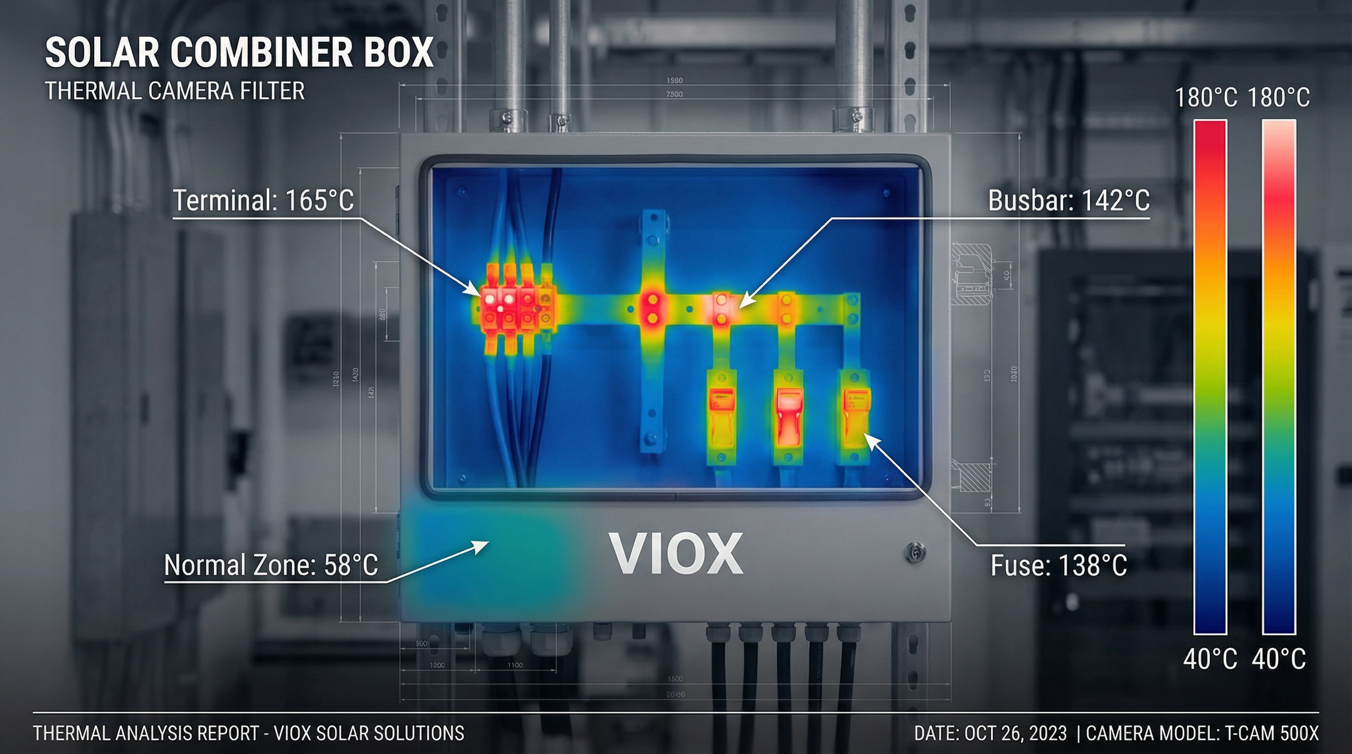
Abnormal temperature rise manifests as localized hot spots significantly exceeding these thresholds. Thermal imaging studies of failing installations show hot spots ranging from 120°C to over 180°C at terminal connections and busbar junctions—temperatures well into the failure zone. At these elevated temperatures, copper oxidizes rapidly, connection resistance increases exponentially, and thermal runaway becomes likely.
Root Cause #1: Undersized Components
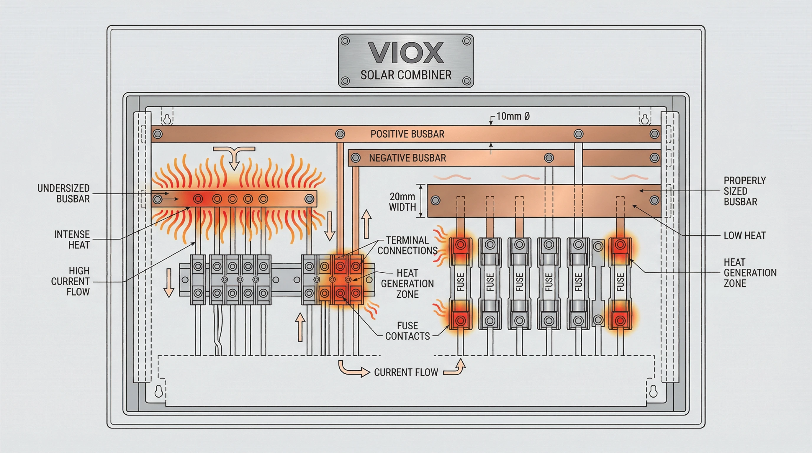
The most fundamental cause of solar combiner box overheating is the selection of components with insufficient current-carrying capacity for the actual operating conditions. Undersizing occurs at multiple levels: terminals, busbars, fuses, and circuit breakers—any of which can become a thermal bottleneck.
Busbar Cross-Sectional Area: Busbar sizing is governed by current density principles. For copper busbars, engineers typically use a conservative current density of 1.2 to 1.6 A/mm². A 500 A continuous current requires approximately 417 mm² minimum cross-section (500 A ÷ 1.2 A/mm²), typically satisfied with a 40mm × 10mm (400 mm²) or 50mm × 10mm (500 mm²) busbar. Aluminum busbars, having lower conductivity, require lower current densities around 0.8 A/mm² and correspondingly larger cross-sections. A narrow busbar not only has higher resistance but also reduced surface area for heat dissipation—a compounding thermal penalty.
The resistance of a busbar follows the formula R = (ρ × L) / A, where ρ is resistivity (1.724 × 10⁻⁸ Ω·m for copper at 20°C), L is length, and A is cross-sectional area. The power loss is P = I² × R. Even a modest undersizing doubles the resistance and thus quadruples heat generation when combined with current increases.
Terminal and Connection Ratings: Terminal blocks and lug connections must be rated for the maximum string current with appropriate safety margins. In solar applications, NEC requires a 125% safety factor on continuous current ratings. A string carrying 12 A continuously requires terminals rated for at least 15 A. Failure to apply this derating leads to terminals operating beyond their thermal design limits, accelerating degradation.
Fuse and Breaker Sizing: Undersized fuses experience thermal degradation and premature opening. Since fuses are rated at 25°C ambient, operation at elevated combiner box internal temperatures (often 60-70°C) requires derating. A fuse with a 0.84 derating factor at 60°C must be uprated to compensate—protecting a 12 A circuit at 60°C requires a nominal 15 A fuse (12 A ÷ 0.84 ≈ 14.3 A). Similarly, circuit breakers calibrated at 40°C lose capacity at higher temperatures; a 100 A breaker may only handle 80-85 A at 60°C internal ambient.
Root Cause #2: Poor Connection Quality
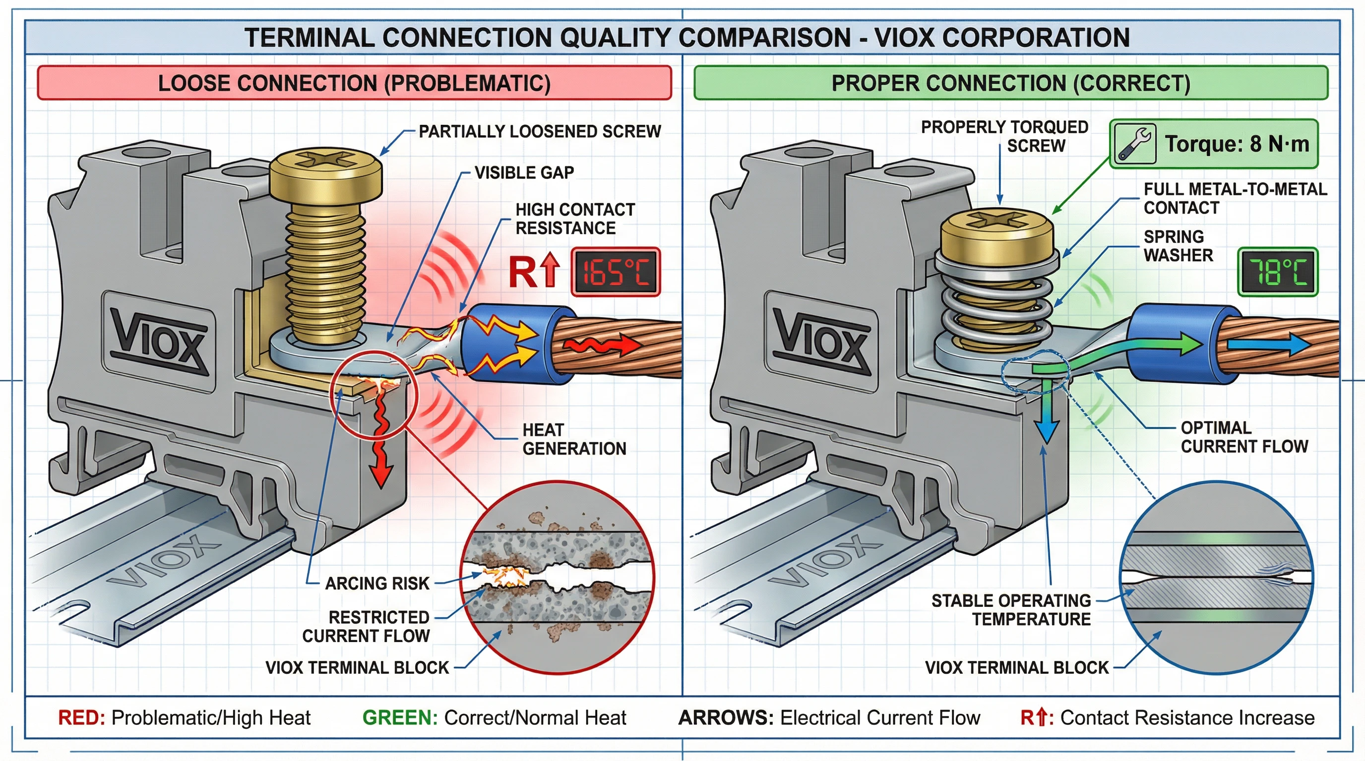
Contact resistance at electrical connections is the single most frequent cause of localized overheating in solar combiner boxes. The power dissipated as heat at any connection point is P = I²R—meaning even small increases in contact resistance generate disproportionate heat. A connection with 10 mΩ resistance carrying 50 A dissipates 25 W (50² × 0.01), concentrated at a single junction point.
Loose Connections and Thermal Cycling: Improperly torqued terminal screws are the most common installation defect. Terminals must be tightened to manufacturer-specified torque values—typically 3-5 N·m for smaller terminals, up to 10-15 N·m for larger busbars. Under-torquing creates poor metal-to-metal contact with high resistance; over-torquing can damage threads and deform contact surfaces, also degrading connection quality.
Thermal cycling exacerbates loose connections over time. As the combiner box heats during peak solar hours and cools at night, the copper conductors and steel terminal hardware expand and contract at different rates (coefficient of thermal expansion mismatch). This daily cycling progressively loosens mechanical connections, increasing contact resistance and accelerating thermal degradation—a positive feedback loop leading to thermal runaway.
Corrosion and Surface Oxidation: Terminal surfaces exposed to moisture, salt air (coastal installations), or industrial contaminants develop oxide layers and corrosion products that dramatically increase contact resistance. Copper oxide has significantly higher resistivity than pure copper. Improperly made connections—inadequate wire stripping, damaged strands, or poorly crimped lugs—create microscopic air gaps that accelerate oxidation.
MC4 connector degradation is increasingly recognized as a heat source. UV exposure degrades the polymer housing, while the spring contacts inside lose tension over years of thermal cycling, increasing resistance at the PV string input connections.
Root Cause #3: Inadequate Thermal Design
Even properly sized components will overheat if the combiner box enclosure cannot dissipate the accumulated heat load. Thermal design encompasses enclosure geometry, ventilation strategy, component spacing, and heat transfer pathways—all of which are frequently neglected in low-cost designs.
Insufficient Ventilation and Airflow: Most solar combiner boxes use sealed NEMA 4 or IP65 enclosures to protect against weather and dust ingress. This sealing eliminates natural convection as a cooling mechanism, trapping heat inside. The internal temperature becomes the sum of external ambient temperature, self-heating from components, and solar radiation absorbed by the enclosure:
T_internal = T_ambient + ΔT_components + ΔT_solar
Without ventilation, internal temperatures can easily exceed 70-80°C in full sun, even when external ambient is only 35-40°C. Heat dissipation relies entirely on conduction through the enclosure walls and radiation from the external surface. The temperature rise (ΔT) is determined by heat load density (W/m²) and enclosure surface area—a smaller enclosure with the same component load suffers higher temperature rise.
Component Spacing and Layout: Internal component arrangement critically affects heat dissipation. Overlapping busbars or tightly grouped fuse holders restrict airflow (even in sealed enclosures, internal convection currents develop) and create localized hot zones. Each heat-generating component—fuse, terminal block, busbar junction—requires adequate spacing to allow heat to spread and dissipate rather than concentrating in one area.
Enclosure Material and Thermal Conductivity: Metal enclosures (stainless steel, aluminum) conduct heat far better than fiberglass or polycarbonate enclosures. Aluminum has particularly high thermal conductivity (~205 W/m·K), effectively acting as a heat sink. Painted or coated surfaces change radiative properties; white or light gray finishes reflect more solar radiation and improve heat dissipation.
Ambient Temperature Derating: Design engineers often fail to apply proper derating for the realistic internal operating environment. If components are selected based on 25°C lab conditions but installed in an enclosure reaching 70°C internal temperature, they operate far outside their thermal envelope. Fuses, circuit breakers, and terminal blocks all require temperature-specific derating curves from manufacturer datasheets.
Root Cause #4: Environmental Factors
Solar combiner boxes operate in harsh outdoor environments where external conditions impose significant thermal stresses beyond the heat generated by electrical components themselves.
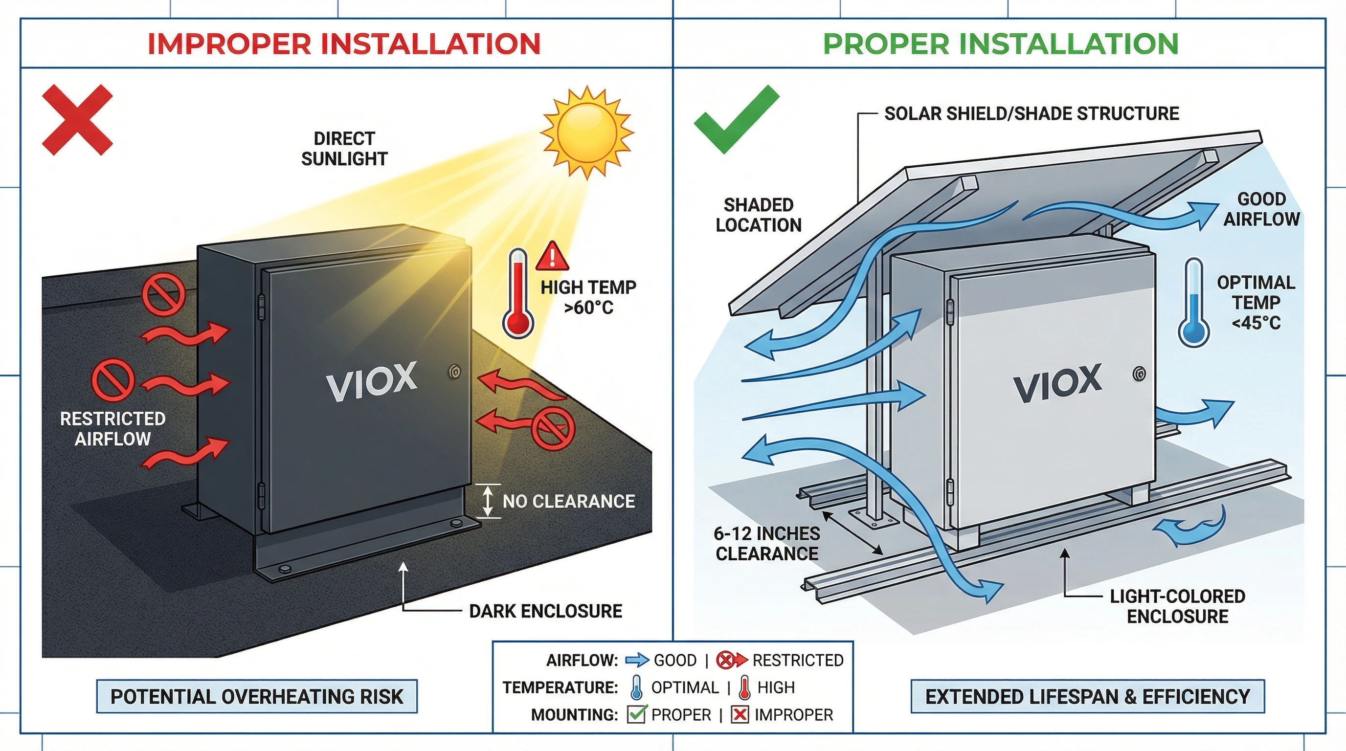
Direct Solar Radiation: A dark-colored enclosure in direct sunlight can absorb 97 W/ft² (peak solar radiation in many regions), adding substantial heat load to the internal temperature. Color dramatically affects absorption: a black enclosure may reach surface temperatures 40-50°C higher than a white enclosure under identical conditions. This solar heat gain transfers directly to the internal components, raising the effective ambient temperature and reducing the temperature differential available for heat dissipation.
Testing under Telcordia GR-487 protocols shows that solar shields—simple shading structures mounted above and around the enclosure—can reduce solar heat gain by over 40%. Yet many field installations mount combiner boxes on sun-facing walls or equipment racks with zero shading provision.
High Ambient Temperature Environments: Installations in desert regions, tropical climates, or on rooftops experience ambient temperatures routinely exceeding 40-45°C. When this is the baseline before adding component self-heating and solar gain, internal temperatures push toward 80-90°C. At these temperatures, even properly sized components approach or exceed their thermal ratings.
Dust Accumulation and Airflow Restriction: In agricultural or desert environments, airborne dust accumulates on enclosure surfaces and clogs any ventilation openings. This dust layer acts as thermal insulation, reducing the enclosure’s ability to radiate heat. For enclosures with filtered ventilation, clogged filters eliminate airflow entirely, causing rapid internal temperature rise. Periodic cleaning is essential but frequently neglected in O&M schedules.
Root Cause #5: Electrical Faults
Certain electrical fault conditions generate abnormal current patterns that produce excess heat even when components are properly sized for normal operation.
String Current Imbalance: When parallel strings feeding the same busbar carry unequal currents due to shading, soiling, or module mismatch, the higher-current strings impose localized thermal stress on their connection points. A busbar designed for evenly distributed current from eight 10 A strings (80 A total) may develop hot spots if one string carries 15 A while others carry 8 A—the connection point for the 15 A string experiences 2.25× higher I²R heating than designed.
Ground Faults and Leakage Currents: Insulation degradation or moisture ingress can create ground faults that divert current through unintended paths, including grounding conductors and enclosure structural elements. These paths typically have higher resistance than the designed current paths, generating heat in unexpected locations. Ground fault currents of even 1-2 A through high-resistance paths can create significant localized heating.
Harmonic Heating: While less common in DC combiner boxes than in AC distribution, harmonic currents from inverter switching or ground-referenced capacitances can create circulating currents that add to thermal loading without contributing to useful power output. These harmonic components increase RMS current above the DC level, raising I²R losses throughout the system.
Diagnosing electrical faults requires careful measurement: string-level current monitoring can reveal imbalance conditions, while thermal imaging identifies unexpected hot spots indicating fault currents. Ground fault detection devices and insulation resistance testing help identify developing problems before they cause thermal damage.
Solutions: Design & Specification
Preventing solar combiner box overheating begins at the design phase with rigorous thermal analysis and component selection based on realistic operating conditions rather than optimistic lab ratings.
Thermal Derating and Current Capacity: Engineers must calculate the realistic internal ambient temperature and apply component-specific derating factors. The process follows three steps:
- Determine Internal Temperature: Calculate T_internal = T_ambient + ΔT_component + ΔT_solar using enclosure manufacturer heat load density charts and solar radiation data for the installation location.
- Apply Component Derating: Use manufacturer derating curves for fuses (typically rated at 25°C), circuit breakers (40°C), and terminal blocks. For example, a fuse protecting a 12 A string at 70°C internal temperature with K_f = 0.8 requires a nominal 15 A rating (12 ÷ 0.8).
- Include Safety Margins: NEC requires 125% continuous current multiplier for solar applications. Apply this factor after thermal derating: required component rating = (I_continuous × 1.25) ÷ K_f.
Busbar Sizing with Thermal Consideration: Select busbars using conservative current densities (1.2 A/mm² for copper, 0.8 A/mm² for aluminum) and verify temperature rise using thermal modeling. For high-current applications, consider increasing cross-section beyond electrical requirements to enhance heat dissipation. Copper busbars are preferred over aluminum for their superior conductivity and thermal performance.
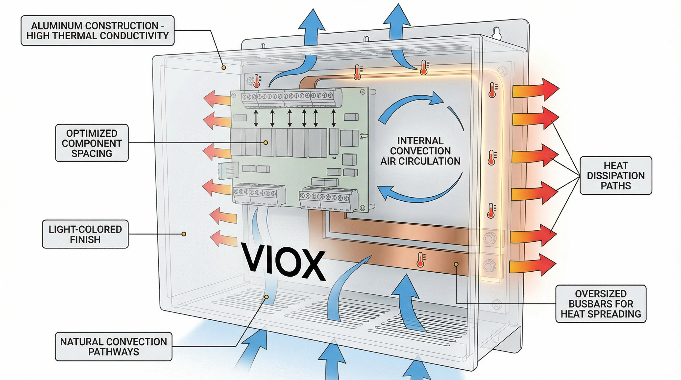
Thermal Management Features: Specify enclosures with design features that facilitate heat dissipation:
- Light-colored finishes (white, light gray) to reflect solar radiation
- Adequate surface area relative to internal heat load
- Aluminum construction for high thermal conductivity
- Internal component mounting that maximizes spacing and airflow
- Optional: passive heat sinks attached to high-load busbars
- For extreme environments: active cooling (thermostatically controlled fans) or heat pipe technology
Material and Contact Surface Selection: Specify tin-plated copper terminals and busbars to resist oxidation. Use spring washers or serrated washers under terminal screws to maintain contact pressure during thermal cycling. Sealed terminal blocks with captive hardware prevent loosening due to vibration.
Solutions: Installation & Maintenance
Proper installation practices and proactive maintenance protocols are essential for preventing thermal failures in field-deployed solar combiner boxes.
Torque Specification Verification: Every terminal connection must be tightened to the manufacturer-specified torque value using a calibrated torque wrench or torque screwdriver. Create and maintain installation records documenting torque values for critical connections. Commission testing should include thermal imaging of all connections under load to verify proper installation before system handover.
Mounting Location and Orientation: Install combiner boxes in locations that minimize solar exposure—north-facing walls (northern hemisphere), shaded areas beneath array structures, or under dedicated weather shields. Ensure adequate clearance around the enclosure (typically 6-12 inches on all sides) to allow natural convection and radiative cooling. Vertical mounting is generally preferred over horizontal to facilitate internal convection currents.
Environmental Protection: In corrosive environments (coastal, industrial), specify combiner boxes with enhanced corrosion protection: 316 stainless steel enclosures, conformal coating on busbars, and sealed terminals. Use dielectric grease on all connections to prevent moisture ingress and oxidation. Ensure proper IP rating for the installation environment—dusty environments require IP65 minimum.
Periodic Thermal Inspection: Implement thermal imaging surveys as part of routine O&M schedules—typically annually for commercial systems, semi-annually for utility-scale installations in harsh environments. Thermal imaging identifies developing hot spots before they cause failures, allowing preventive intervention. Establish baseline thermal profiles during commissioning for comparison.
Re-Torquing and Connection Maintenance: After the first year of operation, re-torque all terminal connections to compensate for thermal cycling effects. This maintenance task is often omitted but critical for long-term reliability. Inspect for signs of corrosion, discoloration, or physical damage at each maintenance interval.
Conclusion: VIOX Electric’s Thermal Engineering Approach
Solar combiner box overheating is a preventable failure mode when engineers apply rigorous thermal analysis, proper component derating, and field-proven design principles. The root causes—undersized components, poor connection quality, inadequate thermal design, environmental stressors, and electrical faults—are well understood, and engineering solutions exist for each.
At VIOX Electric, thermal management is integrated into every phase of solar combiner box design. Our engineering process includes:
- Thermal modeling and validation: CFD analysis of internal temperature distribution under worst-case operating conditions
- Component derating methodology: Selection of busbars, terminals, and protection devices using site-specific temperature calculations and appropriate derating factors
- Quality connection systems: Factory-torqued terminals with spring retention hardware, tin-plated copper contact surfaces, and thermal cycling validation
- Thermal-optimized enclosures: Aluminum construction with light-colored finishes, optimized internal layouts, and heat dissipation features for harsh environments
VIOX combiner boxes undergo thermal validation testing that exceeds UL 1741 requirements, with temperature rise testing at full rated current plus 25% safety margin under controlled elevated ambient conditions. Our engineering team provides thermal analysis support and site-specific derating calculations to help contractors and EPC firms specify the right solution for their installation conditions.
Preventing overheating requires partnership between manufacturers, design engineers, and installation teams. VIOX Electric is committed to providing not just products, but engineering expertise and thermal design guidance to ensure long-term system reliability.
For technical specifications, thermal analysis support, or custom combiner box solutions optimized for your installation environment, contact VIOX Electric‘s application engineering team.
