
တိုက်ရိုက်အဖြေ
စတင်ဖွင့်ချိန်တွင် လျှပ်စစ်ပစ္စည်းတစ်ခုမှ ဆွဲယူသော လျှပ်စီးကြောင်း၏ အမြင့်ဆုံး ချက်ချင်းမြင့်တက်လာမှုကို Inrush current ဟုခေါ်သည်။ ဤယာယီလျှပ်စီးကြောင်းသည် ပစ္စည်းအမျိုးအစားပေါ်မူတည်၍ ပုံမှန်တည်ငြိမ်သော လည်ပတ်လျှပ်စီးကြောင်းထက် ၂ ဆမှ ၃၀ ဆအထိ ရောက်ရှိနိုင်သည်။ ယေဘူယျအားဖြင့် အဆိုပါဖြစ်စဉ်သည် မီလီစက္ကန့်အနည်းငယ်မှ စက္ကန့်အနည်းငယ်အထိ ကြာမြင့်ပြီး ထရန်စဖော်မာများ၊ မော်တာများနှင့် capacitive circuits များကဲ့သို့သော inductive load များတွင် အဓိကဖြစ်ပွားသည်။ စက်မှုနှင့် ကူးသန်းရောင်းဝယ်ရေး လျှပ်စစ်စနစ်များတွင် သင့်လျော်သော circuit breaker အရွယ်အစားကို သတ်မှတ်ခြင်း၊ မလိုလားအပ်သော ခရီးစဉ်များကို ကာကွယ်ခြင်းနှင့် စက်ပစ္စည်း၏ သက်တမ်းကို သေချာစေရန်အတွက် inrush current ကို နားလည်ခြင်းသည် အရေးကြီးပါသည်။.
သော့ထုတ်ယူမှုများ
- Inrush current သည် ခဏတာမြင့်တက်သော လျှပ်စီးကြောင်းဖြစ်သည်။ စက်ပစ္စည်းစတင်ချိန်တွင် ဖြစ်ပေါ်ပြီး ပုံမှန်လည်ပတ်လျှပ်စီးကြောင်းထက် ၂-၃၀ ဆအထိ ရောက်ရှိသည်။
- အဓိကအကြောင်းရင်းများမှာ ထရန်စဖော်မာများတွင် သံလိုက်အူတိုင်ပြည့်ဝခြင်း၊ မော်တာများတွင် ရိုတာရပ်တန့်ခြင်းနှင့် ပါဝါထောက်ပံ့မှုများတွင် capacitor အားသွင်းခြင်းတို့ ပါဝင်သည်။
- Circuit breaker များကို သင့်လျော်သောအရွယ်အစား သတ်မှတ်ရမည်။ overcurrent protection ကိုပေးစွမ်းနိုင်စွမ်းရှိနေစဉ် မလိုလားအပ်သော ခရီးစဉ်များမဖြစ်ပေါ်စေရန် inrush ကို ခံနိုင်ရည်ရှိစေရန်။
- ပုံမှန် inrush ပမာဏများ: ထရန်စဖော်မာများ (rated current ၏ ၈-၁၅ ဆ)၊ မော်တာများ (full load current ၏ ၅-၈ ဆ)၊ LED drivers များ (တည်ငြိမ်သော state ၏ ၁၀-၂၀ ဆ)
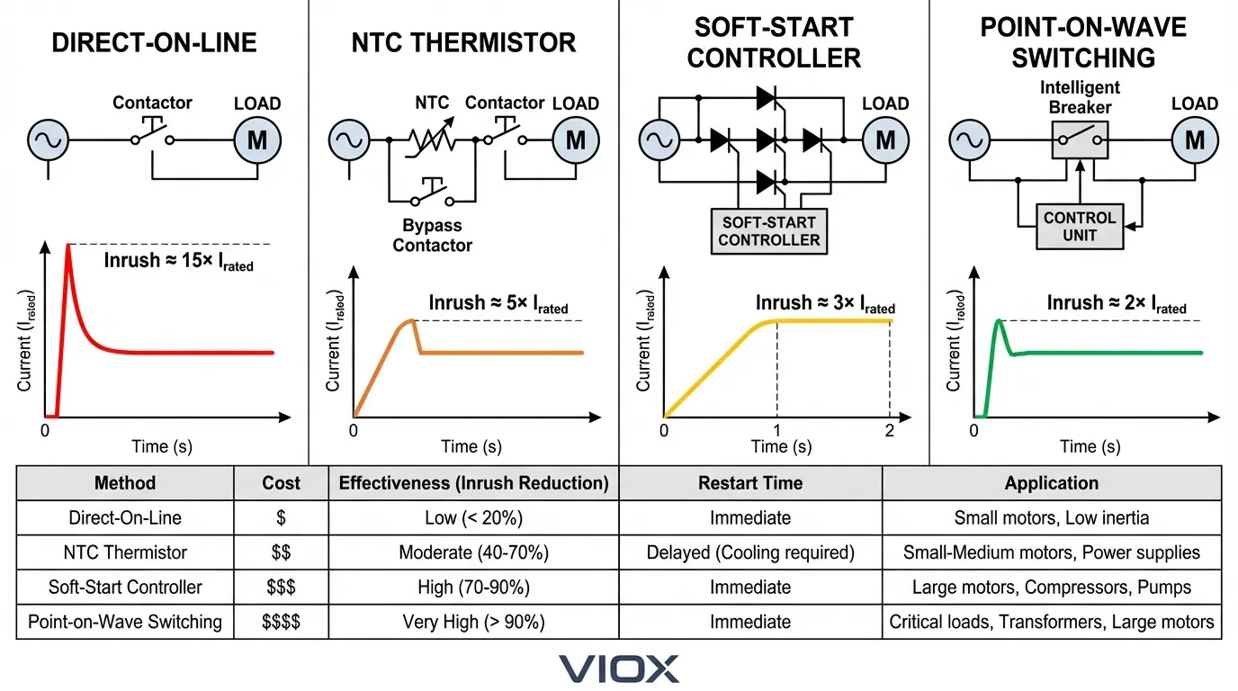
- လျှော့ချရေးနည်းလမ်းများတွင် NTC thermistors များ၊ soft-start circuits များ၊ pre-insertion resistors များ နှင့် point-on-wave switching များ ပါဝင်သည်။
- တွက်ချက်မှုအတွက် လိုအပ်သည်မှာ စက်ပစ္စည်းအမျိုးအစား၊ residual flux၊ switching angle နှင့် system impedance တို့ကို နားလည်ခြင်းဖြစ်သည်။
Inrush Current ဆိုသည်မှာ အဘယ်နည်း။
Input surge current သို့မဟုတ် switch-on surge ဟုလည်းလူသိများသော Inrush current သည် စွမ်းအင်ပေးချိန်တွင် လျှပ်စစ်ပစ္စည်းတစ်ခုထဲသို့ စီးဝင်သော အမြင့်ဆုံးချက်ချင်းလျှပ်စီးကြောင်းကို ကိုယ်စားပြုသည်။ ပုံမှန်လည်ပတ်နေစဉ်အတွင်း အတော်အတန် တည်ငြိမ်နေသော steady-state operating current နှင့်မတူဘဲ inrush current သည် အလွန်မြင့်မားသောပမာဏနှင့် တိုတောင်းသောကြာချိန်တို့ဖြင့် သွင်ပြင်လက္ခဏာရှိသော ယာယီဖြစ်စဉ်တစ်ခုဖြစ်သည်။.
ဤလျှပ်စီးကြောင်းမြင့်တက်မှုသည် ချို့ယွင်းချက်အခြေအနေမဟုတ်ဘဲ လျှပ်စစ်သံလိုက်ပစ္စည်းများကို အုပ်ချုပ်သည့် ရူပဗေဒဆိုင်ရာမူများ၏ သဘာဝအကျိုးဆက်ဖြစ်သည်။ ပါဝါကို ပထမဆုံးအသုံးပြုသောအခါ inductive အစိတ်အပိုင်းများသည် ၎င်းတို့၏သံလိုက်စက်ကွင်းများကို တည်ဆောက်ရမည်၊ capacitors များသည် လည်ပတ်ဗို့အားသို့ အားသွင်းရမည်၊ ခံနိုင်ရည်ရှိသော အပူပေးဒြပ်စင်များသည် အအေးခံနိုင်ရည်တန်ဖိုးများမှ စတင်သည်—၎င်းတို့အားလုံးသည် ပုံမှန်လည်ပတ်ရန်လိုအပ်သည်ထက် များစွာပိုသောလျှပ်စီးကြောင်းကို ယာယီတောင်းဆိုကြသည်။.
Inrush current ၏ပြင်းထန်မှုနှင့်ကြာချိန်သည် စက်ပစ္စည်းအမျိုးအစား၊ စနစ်လက္ခဏာများနှင့် switching ဖြစ်ပေါ်သည့် AC waveform တွင် တိကျသောအချိန်ပေါ်မူတည်၍ သိသိသာသာကွဲပြားသည်။ လျှပ်စစ်အင်ဂျင်နီယာများနှင့် စက်ရုံမန်နေဂျာများအတွက် ယုံကြည်စိတ်ချရသော ကာကွယ်ရေးအစီအစဉ်များကို ဒီဇိုင်းရေးဆွဲရန်နှင့် လုပ်ငန်းလည်ပတ်မှု အနှောင့်အယှက်များကို ကာကွယ်ရန်အတွက် ဤပြောင်းလဲနိုင်သော အရာများကို နားလည်ရန် အရေးကြီးပါသည်။.
Inrush Current ၏ အရင်းခံအကြောင်းရင်းများ
ထရန်စဖော်မာ Inrush- သံလိုက်အူတိုင်ပြည့်ဝခြင်း
ထရန်စဖော်မာများ လျှပ်စစ်စနစ်များတွင် အပြင်းထန်ဆုံး inrush current များကို ကြုံတွေ့ရသည်။ ထရန်စဖော်မာတစ်ခုကို ပထမဆုံးစွမ်းအင်ပေးသောအခါ ၎င်း၏အူတိုင်ရှိ သံလိုက်စီးကြောင်းသည် သုည (သို့မဟုတ် ကျန်ရှိသော သံလိုက်ဓာတ်မှ) ၎င်း၏လည်ပတ်မှုအဆင့်သို့ တည်ဆောက်ရမည်ဖြစ်သည်။ ဗို့အား waveform တွင် မလိုလားအပ်သော အမှတ်တစ်ခုတွင် စွမ်းအင်ပေးခြင်းဖြစ်ပေါ်ပါက—အထူးသဖြင့် ဗို့အားသုညဖြတ်ကျော်ခြင်းတွင်—လိုအပ်သောစီးကြောင်းသည် အူတိုင်၏ပြည့်ဝမှတ်ကို ကျော်လွန်နိုင်သည်။.
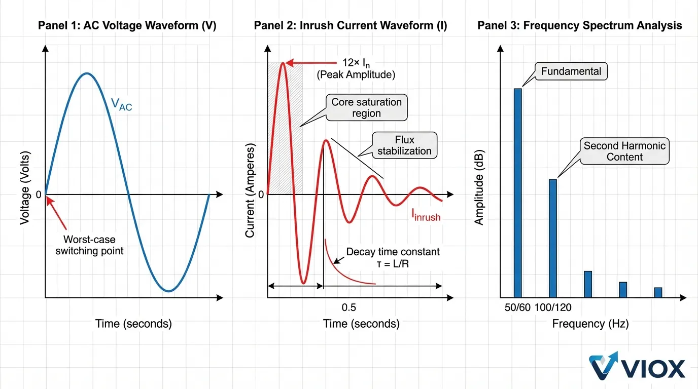
အူတိုင်ပြည့်ဝသွားသည်နှင့် ၎င်း၏သံလိုက်စိမ့်ဝင်နိုင်စွမ်းသည် သိသိသာသာကျဆင်းသွားပြီး သံလိုက်ဓာတ်အားနည်းသွားစေသည်။ impedance သည် အခြေခံအားဖြင့် winding resistance သို့ လျှော့ချလိုက်သည်နှင့် လျှပ်စီးကြောင်းသည် ထရန်စဖော်မာ၏ rated current ထက် ၈-၁၅ ဆအထိ မြင့်တက်လာသည်။ ဤဖြစ်စဉ်ကို ယခင်လည်ပတ်မှုမှ အူတိုင်တွင်ကျန်ရှိသော residual flux က ပိုမိုအားကောင်းစေသည်။ residual flux ၏ polarity နှင့် magnitude သည် လိုအပ်သော flux သို့ ပေါင်းထည့်နိုင်သည် သို့မဟုတ် နုတ်နိုင်သည်၊ inrush current ကို အနည်းငယ်ခန့်မှန်းရခက်စေသည်။.
ထရန်စဖော်မာများရှိ inrush current သည် ဒုတိယ harmonic content ကြွယ်ဝသော လက္ခဏာ asymmetric waveform ကိုပြသပြီး ၎င်းကို short-circuit faults များမှ ခွဲခြားသိမြင်စေသည်။ ဤယာယီသည် သံလိုက်စီးကြောင်းတည်ငြိမ်ပြီး အူတိုင်ပြည့်ဝမှုလျော့နည်းသွားသည်နှင့်အမျှ ၀.၁ မှ ၁ စက္ကန့်အတွင်း ပျက်စီးသွားတတ်သည်။.
မော်တာစတင်လျှပ်စီးကြောင်း
လျှပ်စစ်မော်တာများသည် စတင်ချိန်တွင် ရိုတာသည် ရပ်တန့်နေသောကြောင့် မြင့်မားသော inrush current ကို ဆွဲယူသည်။ လှည့်ပတ်မှုမရှိဘဲ အသုံးချဗို့အားကို ဆန့်ကျင်ရန် counter-electromotive force (CEMF သို့မဟုတ် back-EMF) မရှိပါ။ စတင်လျှပ်စီးကြောင်းကို winding impedance ကသာ ကန့်သတ်ထားပြီး ၎င်းသည် အတော်လေးနည်းသည်။.
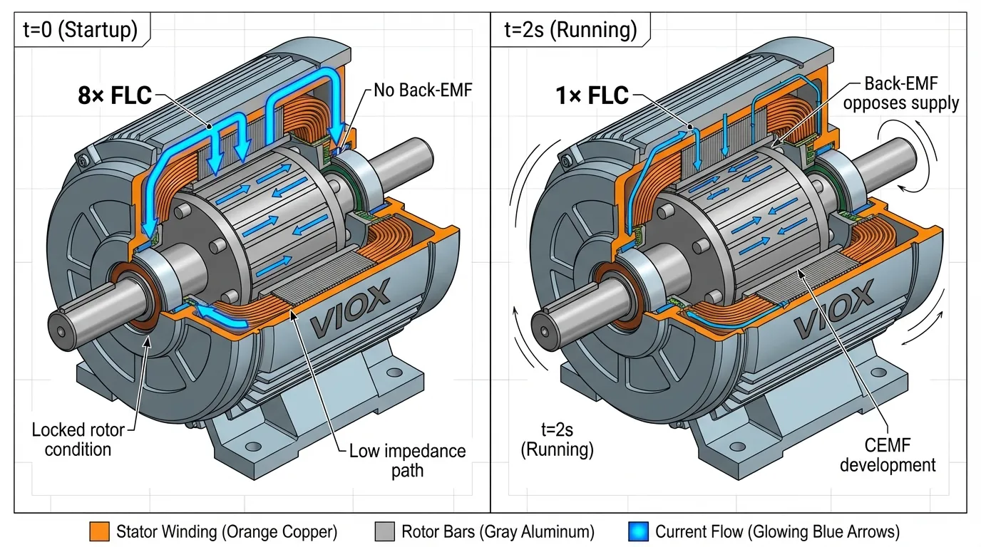
induction motor များအတွက် locked-rotor current သည် ပုံမှန်အားဖြင့် full-load current ၏ ၅ ဆမှ ၈ ဆအထိရှိပြီး အချို့ဒီဇိုင်းများသည် ၁၀ ဆအထိရောက်ရှိနိုင်သည်။ တိကျသောပမာဏသည် မော်တာဒီဇိုင်းပေါ်မူတည်ပြီး မြင့်မားသောစွမ်းဆောင်ရည်ရှိသောမော်တာများသည် winding resistance နည်းပါးသောကြောင့် ယေဘုယျအားဖြင့် inrush မြင့်မားသည်။ ရိုတာအရှိန်မြှင့်လာသည်နှင့်အမျှ back-EMF သည် အရှိန်နှင့်အညီ တိုးတက်လာပြီး တည်ငြိမ်သောလည်ပတ်မှုသို့ရောက်ရှိသည်အထိ လျှပ်စီးကြောင်းဆွဲယူမှုကို တဖြည်းဖြည်းလျှော့ချပေးသည်။.
Motor starters နှင့် contactors များ contact welding သို့မဟုတ် အလွန်အကျွံဝတ်ဆင်ခြင်းမရှိဘဲ ဤထပ်တလဲလဲ inrush ကို ကိုင်တွယ်ရန် အထူးအဆင့်သတ်မှတ်ရမည်။.
Capacitive Load အားသွင်းခြင်း
Switching power supplies များ၊ variable frequency drives များ နှင့် ကြီးမားသော input capacitors ပါရှိသော အခြားအီလက်ထရွန်နစ်ပစ္စည်းများသည် ဖွင့်ချိန်တွင် ပြင်းထန်သော inrush current များကို ဖန်တီးပေးသည်။ အားမသွင်းရသေးသော capacitor သည် မူလက short circuit အဖြစ်ပေါ်လာပြီး source impedance နှင့် circuit resistance တို့ဖြင့်သာ ကန့်သတ်ထားသော အမြင့်ဆုံးလျှပ်စီးကြောင်းကို ဆွဲယူသည်။.
အားသွင်းလျှပ်စီးကြောင်းသည် exponential decay curve ကို လိုက်နာပြီး circuit ၏ RC လက္ခဏာများဖြင့် ဆုံးဖြတ်ထားသော time constant ပါရှိသည်။ အားနည်းသောဒီဇိုင်းထုတ်ထားသော circuits များတွင် peak inrush သည် steady-state current ထက် ၂၀-၃၀ ဆအထိ အလွယ်တကူရောက်ရှိနိုင်သည်။ ခေတ်မီပါဝါအီလက်ထရွန်နစ်ပစ္စည်းများသည် စက်ပစ္စည်းနှင့် upstream ဖြန့်ဖြူးရေးစနစ်များကို ကာကွယ်ရန်အတွက် တက်ကြွသော သို့မဟုတ် passive inrush ကန့်သတ်ခြင်းကို တိုးမြှင့်ထည့်သွင်းထားသည်။.
Incandescent နှင့် အပူပေးဒြပ်စင် အအေးခံနိုင်ရည်
Tungsten-filament incandescent မီးအိမ်များနှင့် ခံနိုင်ရည်ရှိသော အပူပေးဒြပ်စင်များသည် ၎င်းတို့၏ပူပြင်းသောလည်ပတ်မှုအခြေအနေနှင့် နှိုင်းယှဉ်ပါက အေးသောအခါတွင် ခံနိုင်ရည်သိသိသာသာနည်းပါးသည်။ Tungsten ၏ခံနိုင်ရည်သည် အခန်းအပူချိန်မှ လည်ပတ်မှုအပူချိန် (incandescent မီးလုံးများအတွက် ၂,၈၀၀ ဒီဂရီစင်တီဂရိတ်ခန့်) အထိ အပူပေးသောအခါ ၁၀-၁၅ ဆခန့် တိုးလာသည်။.
ဤအအေးခံနိုင်ရည်အကျိုးသက်ရောက်မှုသည် 100W incandescent မီးအိမ်သည် filament အပူချိန်မတက်မီ ပထမမီလီစက္ကန့်အနည်းငယ်အတွင်း ၎င်း၏ rated current ထက် ၁၀-၁၅ ဆ ဆွဲယူနိုင်သည်ဟု ဆိုလိုသည်။ တစ်ဦးချင်းမီးအိမ်များသည် အနည်းဆုံးပြဿနာများကို တင်ပြသော်လည်း incandescent မီးအလင်းရောင် သို့မဟုတ် အပူပေးဒြပ်စင်များ၏ ကြီးမားသောဘဏ်များသည် ထည့်သွင်းစဉ်းစားရမည့် သိသာထင်ရှားသော inrush ကို ဖန်တီးနိုင်သည်။ circuit breaker ရွေးချယ်မှု.
လျှပ်စစ်စနစ်များအပေါ် Inrush Current ၏ အကျိုးသက်ရောက်မှုများ
Circuit Breaker မလိုလားအပ်သော ခရီးစဉ်များ
inrush current ကြောင့်ဖြစ်ရသော အဖြစ်အများဆုံးလည်ပတ်မှုပြဿနာမှာ မလိုလားအပ်သော ခရီးစဉ်များဖြစ်သည်။ ဆားကစ်မိျ နှင့် fuses များဖြစ်သည်။ အကာအကွယ်ပစ္စည်းများသည် အန္တရာယ်ရှိသော fault current များနှင့် benign inrush transients များကို ခွဲခြားရမည်—စိန်ခေါ်မှုရှိသော အင်ဂျင်နီယာလုပ်ငန်းတစ်ခုဖြစ်သည်။.
Thermal-magnetic circuit breakers ခဏတာ overcurrents များကို ခံနိုင်ရည်ရှိပြီး ဆက်တိုက်ဖြစ်ပေါ်နေသော faults များကို လျင်မြန်စွာတုံ့ပြန်သည့် time-current လက္ခဏာကို အသုံးပြုပါ။ သို့သော် inrush magnitude သို့မဟုတ် ကြာချိန်သည် breaker ၏ tolerance envelope ထက်ကျော်လွန်ပါက မလိုအပ်ဘဲ ခရီးထွက်ပါလိမ့်မည်။ ၎င်းသည် အထူးသဖြင့် MCBs နှင့် MCCBs ထရန်စဖော်မာများနှင့် downstream load များကို ကာကွယ်ရမည်ဖြစ်သည်။.
circuit breakers များရှိ ချက်ချင်းခရီးစဉ်ဒြပ်စင်သည် ပုံမှန်အားဖြင့် rated current ၏ ၅-၁၅ ဆကြားတွင် သတ်မှတ်ထားပြီး trip curve (MCBs အတွက် B, C သို့မဟုတ် D curve) ပေါ်မူတည်သည်။ ထရန်စဖော်မာ inrush သည် ဤအကန့်အသတ်များကို အလွယ်တကူကျော်လွန်နိုင်ပြီး စနစ်ဒီဇိုင်းရေးဆွဲစဉ်အတွင်း ဂရုတစိုက်ညှိနှိုင်းရန်လိုအပ်သည်။ နားလည်ခြင်း ခရီးစဉ်မျဉ်းကွေးများ သင့်လျော်သောကာကွယ်ရေးညှိနှိုင်းမှုအတွက် မရှိမဖြစ်လိုအပ်ပါသည်။.
ဗို့အားကျဆင်းခြင်းနှင့် ပါဝါအရည်အသွေးပြဿနာများ
မြင့်မားသော inrush current များသည် လျှပ်စစ်ဖြန့်ဖြူးရေးစနစ်တစ်လျှောက်တွင် ခဏတာဗို့အားကျဆင်းစေသည်။ ဗို့အားကျဆင်းမှုပမာဏသည် source impedance နှင့် inrush current magnitude ပေါ်မူတည်ပြီး Ohm ၏နိယာမကို လိုက်နာသည်- ΔV = I_inrush × Z_source။.
မြင့်မားသော impedance သို့မဟုတ် ကန့်သတ်စွမ်းရည်ရှိသော စနစ်များတွင် ကြီးမားသော load များမှ inrush သည် 10-20% သို့မဟုတ် ထို့ထက်ပိုသော ဗို့အားကျဆင်းမှုကို ဖြစ်စေနိုင်သည်။ ဤကျဆင်းမှုများသည် အခြားချိတ်ဆက်ထားသော စက်ပစ္စည်းများကို ထိခိုက်စေနိုင်ပြီး ဖြစ်ပေါ်စေနိုင်သည်-
- ကွန်ပျူတာနှင့် PLC ပြန်လည်စတင်ခြင်း
- မီးရောင်တဖျပ်ဖျပ်လင်းခြင်း
- မော်တာအမြန်နှုန်းကွဲပြားခြင်း
- ထိလွယ်ရှလွယ် အီလက်ထရွန်နစ်ပစ္စည်း ချို့ယွင်းခြင်း
- ဗို့အားစောင့်ကြည့်ရေး relay activation
ကြီးမားသောမော်တာများ သို့မဟုတ် ထရန်စဖော်မာများစွာပါရှိသော စက်မှုလုပ်ငန်းများသည် စနစ်တစ်ခုလုံးကို မတည်မငြိမ်ဖြစ်စေနိုင်သည့် စုပေါင်းဗို့အားကျဆင်းမှုကို ကာကွယ်ရန်အတွက် စတင်မှုကို ဂရုတစိုက်စီစဉ်ရမည်ဖြစ်သည်။.
စက်ပစ္စည်းပေါ်တွင် စက်ပိုင်းဆိုင်ရာနှင့် အပူဖိစီးမှု
ထပ်ခါထပ်ခါ inrush ဖြစ်ရပ်များသည် လျှပ်စစ်ပစ္စည်းများကို သိသာထင်ရှားသော စက်ပိုင်းဆိုင်ရာနှင့် အပူဖိစီးမှုဖြစ်စေသည်။ မြင့်မားသောလျှပ်စီးကြောင်းများမှထုတ်ပေးသော လျှပ်စစ်သံလိုက်အားများသည် လျှပ်စီးကြောင်း၏စတုရန်းနှင့်အချိုးကျသည် (F ∝ I² )၊ ဆိုလိုသည်မှာ 10× inrush သည် ပုံမှန်စက်ပိုင်းဆိုင်ရာအားထက် 100× ဖန်တီးပေးသည်။.
ထရန်စဖော်မာများတွင် ဤအားများသည် winding supports များနှင့် insulation များကို ဖိစီးစေပြီး စွမ်းအင်ပေးစက်ဝန်းထောင်ပေါင်းများစွာအပေါ်တွင် စုပြုံပျက်စီးမှုကို ဖြစ်စေနိုင်သည်။. Contactors နှင့် motor starters မြင့်မားသော inrush switching အတွင်း contact erosion နှင့် welding အန္တရာယ်ကို ကြုံတွေ့ရသည်။.
inrush အတွင်း I²t အပူပေးခြင်းမှ အပူဖိစီးမှုသည် ကြာချိန်တိုတောင်းသော်လည်း insulation ကို ယိုယွင်းစေပြီး စက်ပစ္စည်း၏ သက်တမ်းကို လျှော့ချနိုင်သည်။ ဒါကြောင့် အပူလွန်ကဲမှု အကာအကွယ်ပေးသည့် ရီလေးများ နှင့် electronic trip units များသည် inrush immunity algorithms များကို ထည့်သွင်းရမည်ဖြစ်သည်။.
Harmonic Distortion နှင့် EMI
Transformer inrush current contains significant harmonic content, particularly second and third harmonics. This harmonic-rich waveform can:
- Interfere with power quality monitoring equipment
- Cause resonance in power factor correction capacitor banks
- Inject noise into communication systems
- Trigger sensitive မြေစိုက်ချို့ယွင်းမှု ကာကွယ်ရေး devices
- Create electromagnetic interference (EMI) affecting nearby electronic equipment
ခေတ်မီသည်။ အီလက်ထရောနစ် ခရီးစဉ်ယူနစ်များ must filter out these harmonic components to avoid false tripping while maintaining sensitivity to genuine fault conditions.
Inrush Current by Equipment Type
| ပစ္စည်းကိရိယာ အမျိုးအစား | Typical Inrush Magnitude | ကြာချိန် | Primary Cause |
|---|---|---|---|
| ပါဝါထရန်စဖော်မာများ | 8-15× rated current | 0.1-1.0 seconds | Core saturation, residual flux |
| ဖြန့်ဖြူးရေး ထရန်စဖော်မာများ | 10-15× rated current | 0.1-0.5 စက္ကန့် | Magnetic flux establishment |
| Induction Motors (DOL) | 5-8× full load current | 0.5-2.0 seconds | Locked rotor, no back-EMF |
| Synchronous Motors | 6-10× full load current | 1.0-3.0 seconds | Starting torque requirements |
| Switching Power Supplies | 10-30× steady state | 1-10 milliseconds | Input capacitor charging |
| LED Drivers များ | 10-20× operating current | 1-5 မီလီစက္ကန့် | Capacitive input stage |
| Incandescent Lamps | 10-15× rated current | 5-50 milliseconds | Cold filament resistance |
| Heating Elements | 1.5-3× rated current | 0.1-1.0 seconds | Cold resistance effect |
| Capacitor ဘဏ်များ | 20-50× rated current | 5-20 milliseconds | Zero initial voltage |
| Variable Frequency Drives | 15-40× operating current | 5-50 milliseconds | DC bus capacitor charging |
How to Calculate Inrush Current
Transformer Inrush Current Calculation
Accurate prediction of transformer inrush current is complex due to the nonlinear behavior of magnetic cores and the influence of residual flux. However, practical estimation methods exist for engineering purposes.
Empirical Method:
I_inrush = K × I_rated
Where:
- K = Inrush factor (typically 8-15 for distribution transformers, 10-20 for large power transformers)
- I_rated = Transformer rated current = kVA / (√3 × kV) for three-phase
ဥပမာ: A 500 kVA, 480V three-phase transformer:
- I_rated = 500,000 / (√3 × 480) = 601 A
- I_inrush = 12 × 601 = 7,212 A (using K=12)
IEEE/IEC Method with Saturation Factor:
I_inrush = (2 × V_peak × S_f) / (ω × L_m)
Where:
- V_peak = Peak voltage
- S_f = Saturation factor (1.4-2.0, depending on core material and switching angle)
- ω = Angular frequency (2πf)
- L_m = Magnetizing inductance
The saturation factor accounts for worst-case switching at voltage zero-crossing with maximum residual flux in the unfavorable direction.
Motor Inrush Current Calculation
Motor inrush current is typically specified by the manufacturer as the locked-rotor current (LRC) or using a code letter on the nameplate.
Using LRC Ratio:
I_inrush = LRC_ratio × I_full_load
Where LRC_ratio typically ranges from 5.0 to 8.0 for standard induction motors.
NEMA ကုဒ်အက္ခရာကို အသုံးပြုခြင်း:
မော်တာအမည်ပြားတွင် မြင်းကောင်ရေအား တစ်ခုလျှင် လော့ခ်ချထားသော ရိုတာ kVA ကို ညွှန်ပြသော ကုဒ်အက္ခရာ (A မှ V အထိ) ပါဝင်သည်။
I_inrush = (Code_kVA × HP × 1000) / (√3 × Voltage)
ဥပမာအားဖြင့်၊ ကုဒ်အက္ခရာ G (5.6-6.29 kVA/HP) ပါသော 50 HP, 480V မော်တာအတွက်-
- I_inrush = (6.0 × 50 × 1000) / (√3 × 480) = 361 A
Capacitive Load Inrush တွက်ချက်ခြင်း
သိသာထင်ရှားသော capacitance ပါသော ဆားကစ်များအတွက်-
I_inrush_peak = V_peak / Z_total
Z_total တွင် source impedance, wiring resistance နှင့် inrush ကန့်သတ်အစိတ်အပိုင်းများ ပါဝင်သည်။.
အားသွင်းနေစဉ်အတွင်း capacitor တွင် သိုလှောင်ထားသော စွမ်းအင်-
E = ½ × C × V²
ဤစွမ်းအင်ထည့်သွင်းစဉ်းစားမှုသည် အရေးကြီးပါသည်။ ဖျူး နှင့် ဆားကစ်အနိုင်အထက် I²t အဆင့်သတ်မှတ်ချက်များ။.
Inrush Current နှင့် Short Circuit Current နှိုင်းယှဉ်ခြင်း
| လက္ခဏာ | Inrush လက်ရှိ | Short Circuit Current |
|---|---|---|
| သဘာဝ | ယာယီ၊ မိမိကိုယ်ကို ကန့်သတ်ခြင်း | ရှင်းလင်းသည်အထိ ထိန်းထားသည်။ |
| ပြင်းအား | အဆင့်သတ်မှတ်ထားသော current ၏ 2-30 ဆ | အဆင့်သတ်မှတ်ထားသော current ၏ 10-100 ဆ |
| ကြာချိန် | မီလီစက္ကန့်မှ စက္ကန့်အထိ | ကာကွယ်မှုမလုပ်ဆောင်မချင်း ဆက်တိုက် |
| လှိုင်းပုံစံ | Asymmetric, harmonic-rich | Symmetric, အခြေခံကြိမ်နှုန်း |
| အကြောင်းရင်း | ပုံမှန်အားသွင်းခြင်း | လျှပ်ကာပျက်ကွက်ခြင်း၊ ချို့ယွင်းချက် |
| စနစ်တုံ့ပြန်မှု | ကာကွယ်မှုကို မခလုတ်သင့်ပါ။ | ကာကွယ်မှုကို ချက်ချင်းခလုတ်တိုက်ရမည်။ |
| ခန့်မှန်းနိုင်စွမ်း | အနည်းငယ်ခန့်မှန်းနိုင်သည်။ | ချို့ယွင်းချက်တည်နေရာပေါ်တွင် မူတည်သည်။ |
| ပစ္စည်းပျက်စီးခြင်း။ | စနစ်တကျ ဒီဇိုင်းထုတ်ထားလျှင် အနည်းဆုံး | ပြင်းထန်သည်၊ အလွန်အန္တရာယ်များနိုင်သည်။ |
ဤခြားနားချက်ကို နားလည်ခြင်းသည် အလွန်အရေးကြီးပါသည်။ ကာကွယ်မှု ညှိနှိုင်းခြင်းအတွက် နှင့် ဘေးကင်းမှုကို ထိန်းသိမ်းထားစဉ်တွင် အနှောင့်အယှက်ဖြစ်စေသော ခလုတ်တိုက်ခြင်းကို ကာကွယ်ခြင်း။.
Inrush Current အတွက် လျှော့ချရေးနည်းဗျူဟာများ
NTC Thermistor Inrush Limiters
Negative Temperature Coefficient (NTC) thermistors သည် အပလီကေးရှင်းများစွာအတွက် ရိုးရှင်းပြီး ကုန်ကျစရိတ်သက်သာသော inrush ကန့်သတ်ဖြေရှင်းချက်ကို ပေးပါသည်။ ဤကိရိယာများသည် အေးနေချိန်တွင် ခံနိုင်ရည်မြင့်မားပြီး ကနဦး current စီးဆင်းမှုကို ကန့်သတ်ထားသည်။ current သည် thermistor မှတဆင့် ဖြတ်သန်းသွားသည်နှင့်အမျှ မိမိကိုယ်ကို အပူပေးခြင်းသည် စက္ကန့်ပိုင်းအတွင်း ၎င်း၏ခံနိုင်ရည်ကို လျစ်လျူရှုနိုင်သော အဆင့်သို့ လျှော့ချပေးပြီး ပုံမှန်လည်ပတ်မှုကို ခွင့်ပြုသည်။.
အားသာချက်များ
- ကုန်ကျစရိတ်သက်သာပြီး ရိုးရှင်းသော အကောင်အထည်ဖော်မှု
- ထိန်းချုပ်ဆားကစ်မလိုအပ်ပါ။
- PCB တပ်ဆင်ရန်အတွက် သင့်လျော်သော ကျစ်လစ်သိပ်သည်းသော အရွယ်အစား
- capacitive နှင့် resistive load များအတွက် ထိရောက်မှုရှိသည်။
ကန့်သတ်ချက်များ-
- လုပ်ဆောင်ချက်များကြားတွင် အအေးခံချိန်လိုအပ်သည် (ပုံမှန်အားဖြင့် 60+ စက္ကန့်)
- မကြာခဏ အဖွင့်အပိတ် စက်ဝန်းအတွက် မသင့်တော်ပါ။
- အလယ်အလတ် ပါဝါအဆင့်များအတွက် ကန့်သတ်ထားသည်။
- short-circuit ကာကွယ်မှုစွမ်းရည်မရှိပါ။
NTC thermistors များကို switching power supplies, motor drives နှင့် electronic equipment များတွင် ကျယ်ကျယ်ပြန့်ပြန့်အသုံးပြုကြသော်လည်း လျင်မြန်စွာ ပြန်လည်စတင်နိုင်စွမ်းလိုအပ်သော စက်မှုလုပ်ငန်းသုံးပစ္စည်းများအတွက် သင့်လျော်မှုနည်းပါသည်။.
Soft-Start ဆားကစ်များနှင့် ထိန်းချုပ်ကိရိယာများ
Soft-start စနစ်များသည် သံလိုက်စက်ကွင်းနှင့် စက်ပိုင်းဆိုင်ရာ inertia ကို တဖြည်းဖြည်း တည်ဆောက်နိုင်စေရန်အတွက် ထိန်းချုပ်ထားသော အချိန်ကာလတစ်ခုအတွင်း load သို့ ဗို့အားကို တဖြည်းဖြည်း အသုံးချသည်။ မော်တာအပလီကေးရှင်းများအတွက်, soft-starters များသည် thyristor သို့မဟုတ် IGBT power electronics ကို အသုံးပြု၍ ဗို့အားကို သုညမှ အပြည့်အထိ စက္ကန့်အတော်ကြာအောင် တိုးမြှင့်ပေးသည်။.
အကျိုးကျေးဇူးများ
- inrush ကို full load current ၏ 2-4 ဆအထိ လျှော့ချပေးသည်။
- မောင်းနှင်ထားသော စက်ပစ္စည်းများအတွက် စက်ပိုင်းဆိုင်ရာ တုန်လှုပ်မှုကို အနည်းဆုံးဖြစ်စေသည်။
- စက်ပစ္စည်းသက်တမ်းကို တိုးမြှင့်ပေးသည်။
- အခြား load များအပေါ် ဗို့အားကျဆင်းမှု သက်ရောက်မှုကို လျှော့ချပေးသည်။
- မကြာခဏ စတင်ရန်အတွက် သင့်လျော်သည်။
ထည့်သွင်းစဉ်းစားချက်များ-
- direct-on-line စတင်ခြင်းထက် ကုန်ကျစရိတ်ပိုမိုမြင့်မားသည်။
- ramp ကာလအတွင်း အပူထုတ်ပေးသည်။
- သင့်လျော်သော အရွယ်အစားနှင့် အအေးခံရန် လိုအပ်သည်။
- ဆက်တိုက်လည်ပတ်ရန်အတွက် bypass contactor လိုအပ်နိုင်သည်။
Soft-start နည်းပညာသည် စက်ပိုင်းဆိုင်ရာ ဖိစီးမှုကို လျှော့ချခြင်းသည် ကုန်ကျစရိတ်ပိုမိုမြင့်မားမှုကို မျှတစေသည့် ကြီးမားသော မော်တာများ၊ compressors များနှင့် conveyor စနစ်များအတွက် အထူးအရေးပါသည်။.
Pre-Insertion Resistors နှင့် Reactors
အချို့သော ဆားကစ်မိျ ခလုတ်ဂီယာများနှင့် ခလုတ်များသည် ပိတ်နေစဉ်အတွင်း ခဏတာခုခံအားထည့်သွင်းပေးပြီး flux တည်ငြိမ်ပြီးနောက် ၎င်းကိုရှောင်ကွင်းပေးသည့် ကြိုတင်ထည့်သွင်းခုခံကိရိယာများပါဝင်သည်။ ဤနည်းပညာသည် ထရန်စဖော်မာပြောင်းခြင်းအတွက် ဗို့အားမြင့်ဆားကစ်ဘရိတ်ကာများတွင် အသုံးများသည်။.
အလားတူပင်၊ စီးရီးရီအက်တာများသည် impedance ကိုထည့်ခြင်းဖြင့် inrush ကိုကန့်သတ်နိုင်သော်လည်း ပုံမှန်လည်ပတ်နေစဉ်အတွင်း ဆားကစ်တွင်ရှိနေဆဲဖြစ်ပြီး ဆက်တိုက်ဗို့အားကျဆင်းခြင်းနှင့် ပါဝါဆုံးရှုံးမှုကိုဖြစ်စေသည်။.
Point-on-Wave Switching
အဆင့်မြင့်ထိန်းချုပ်ထားသော ခလုတ်ကိရိယာများသည် inrush ကိုအနည်းဆုံးဖြစ်အောင် ဗို့အားလှိုင်းပုံစံပေါ်ရှိ အကောင်းဆုံးအမှတ်နှင့် ဆားကစ်ဘရိတ်ကာပိတ်ခြင်းကို တစ်ပြိုင်တည်းချိန်ကိုက်သည်။ ထရန်စဖော်မာများအတွက်၊ ဗို့အားအထွတ်အထိပ်အနီး (flux လိုအပ်ချက်အနည်းဆုံးဖြစ်သည့်အခါ) ပိတ်ခြင်းသည် inrush ကို 50-80% လျှော့ချနိုင်သည်။.
ဤနည်းပညာသည် လိုအပ်သည်-
- အချိန်နှင့်တပြေးညီ ဗို့အားစောင့်ကြည့်ခြင်း
- တိကျသောအချိန်ကိုက်ထိန်းချုပ်မှု (sub-millisecond တိကျမှု)
- ကျန်ရှိသော flux အကြောင်း အသိပညာ (အဆင့်မြင့်စနစ်များ)
- အသိဉာဏ်ရှိသော အီလက်ထရွန်းနစ် ထိန်းချုပ်ကိရိယာများ
ပိုမိုစျေးကြီးသော်လည်း၊ point-on-wave switching သည် အရေးကြီးသောအသုံးချပရိုဂရမ်များအတွက် အထိရောက်ဆုံး inrush လျှော့ချမှုကိုပေးစွမ်းပြီး တဖြည်းဖြည်းအသုံးများလာသည်။ အလိုအလျောက်လွှဲပြောင်းခလုတ်များ နှင့် utility substations များ။.
Sequential Energization
ထရန်စဖော်မာများ သို့မဟုတ် ကြီးမားသောဝန်များစွာပါရှိသော စနစ်များတွင်၊ စွမ်းအင်ပေးသည့်အစီအစဥ်ကို အလှည့်ကျစီခြင်းသည် ထောက်ပံ့မှုကိုလွှမ်းမိုးခြင်းမှ စုပြုံနေသော inrush ကိုကာကွယ်ပေးသည်။ စတင်မှုတစ်ခုစီကြားတွင် 5-10 စက္ကန့်ကြာနှောင့်နှေးခြင်းသည် နောက်တစ်ခုမစတင်မီ ယာယီတစ်ခုစီကို ပျက်စီးစေပါသည်။.
ဤချဉ်းကပ်မှုသည် အထူးအရေးကြီးသည်-
- Switchgear ထရန်စဖော်မာများစွာပါရှိသော တပ်ဆင်မှုများ
- UPS စနစ်များစွာပါရှိသော ဒေတာစင်တာများ
- ပါဝါပြန်လည်ရရှိပြီးနောက် စက်မှုလုပ်ငန်းဆိုင်ရာ အဆောက်အဦများ
- Solar combiner boxes အင်ဗာတာများစွာပါရှိသော
သင့်လျော်သောအစီအစဥ်ကျသောယုတ္တိဗေဒကို အကောင်အထည်ဖော်နိုင်သည်။ ထိန်းချုပ်ဘောင်များ timer များနှင့် interlocking relays များကိုအသုံးပြုခြင်း။.
Circuit Breaker ရွေးချယ်မှုဆိုင်ရာ ထည့်သွင်းစဉ်းစားချက်များ
ခရီးစဉ်မျဉ်းကွေးများနှင့် Inrush ခံနိုင်ရည်ကို နားလည်ခြင်း
Circuit breaker ခရီးစဉ်မျဉ်းကွေးများ အပူနှင့်သံလိုက်ခရီးစဉ်ဒြပ်စင်များအတွက်အချိန်-လက်ရှိဆက်ဆံရေးကိုသတ်မှတ်ပါ။ inrush ခံနိုင်ရည်အတွက်၊ အဓိက parameters များမှာ-
Thermal Trip Element:
- I²t အပူပေးအကျိုးသက်ရောက်မှုကို တုံ့ပြန်သည်။
- ခဏတာ overcurrents ကို သည်းခံသည်။
- ပုံမှန်အားဖြင့် 1.5× အဆင့်သတ်မှတ်ထားသော လက်ရှိကို အကန့်အသတ်မရှိ ခွင့်ပြုသည်။
- မိနစ်ပိုင်းအတွင်း 2-3× အဆင့်သတ်မှတ်ထားသော လက်ရှိတွင် ခရီးစဉ်များ
သံလိုက်ခရီးစဉ်ဒြပ်စင် (ချက်ချင်း):
- လက်ရှိပမာဏကို တုံ့ပြန်သည်။
- အမျိုးအစား B: 3-5× In (လူနေအိမ်အသုံးချပရိုဂရမ်များ)
- အမျိုးအစား C: 5-10× In (စီးပွားဖြစ်/အလင်းစက်မှု)
- အမျိုးအစား D: 10-20× In (မော်တာနှင့် ထရန်စဖော်မာဝန်များ)
ထရန်စဖော်မာကာကွယ်မှုအတွက်၊ အမျိုးအစား D မျဉ်းကွေး MCB များ သို့မဟုတ် ချိန်ညှိနိုင်သော MCCB များသည် ချက်ချင်းဆက်တင်များ (10-15× In) မြင့်မားစွာလိုအပ်ပြီး စွမ်းအင်ပေးနေစဉ်အတွင်း အနှောင့်အယှက်ဖြစ်ခြင်းကို ရှောင်ရှားရန်လိုအပ်ပါသည်။.
Upstream နှင့် Downstream ကာကွယ်ရေးနှင့် ညှိနှိုင်းခြင်း
ရေရေရာရာ ရွေးချယ်မှုနှင့် ညှိနှိုင်းခြင်း ချို့ယွင်းချက်နှင့် အနီးဆုံး ဆားကစ်ဘရိတ်ကာသာ လည်ပတ်ကြောင်း သေချာစေပြီး ဘရိတ်ကာအားလုံးသည် သက်ဆိုင်ရာဝန်များမှ inrush ကို သည်းခံသည်။ ဤသည်မှာ လိုအပ်သည်-
- အကာအကွယ်ကိရိယာအားလုံးအတွက် အချိန်-လက်ရှိမျဉ်းကွေးခွဲခြမ်းစိတ်ဖြာခြင်း
- inrush ပမာဏသည် ချက်ချင်းခရီးစဉ်ဆက်တင်များအောက်တွင် ကျရောက်ကြောင်း အတည်ပြုခြင်း
- inrush ကြာချိန်သည် အပူဒြပ်စင်ခံနိုင်ရည်အတွင်းရှိကြောင်း အတည်ပြုခြင်း
- ထည့်သွင်းစဉ်းစားခြင်း short-circuit အဆင့်သတ်မှတ်ချက်များ နှင့် ချိုးဖျက်နိုင်စွမ်း
ခေတ်မီသည်။ အီလက်ထရောနစ် ခရီးစဉ်ယူနစ်များ စွမ်းအင်ပေးပြီးနောက် ပထမစက်ဝန်းအနည်းငယ်အတွင်း ခရီးစဉ်ကို ခေတ္တရပ်တန့်စေသည့် ပရိုဂရမ်ပြုလုပ်နိုင်သော inrush ထိန်းချုပ်မှုအင်္ဂါရပ်များကို ပေးဆောင်ပြီး inrush နှင့် ချို့ယွင်းချက်အခြေအနေများကြားတွင် သာလွန်ကောင်းမွန်သော ခွဲခြားဆက်ဆံမှုကို ပေးစွမ်းသည်။.
Special Considerations for Different Applications
မော်တာကာကွယ်ရေး-
- သုံးပါ။ အလုံးစုံ load ကာကွယ်မှုအတွက် သို့မဟုတ် မော်တာအဆင့်သတ်မှတ်ချက်များပါရှိသော MCCB များ
- လည်ပတ်ကာကွယ်မှုအတွက် လော့ခ်ချထားသော-ရိုတာလက်ရှိ လိုက်ဖက်ညီမှုကို စစ်ဆေးပါ။
- Consider အပူလွန်ကဲမှု အကာအကွယ်ပေးသည့် ရီလေးများ လည်ပတ်ကာကွယ်မှုအတွက်
- မကြာခဏစတင်သည့်အပလီကေးရှင်းများအတွက် ထည့်သွင်းစဉ်းစားပါ။
Transformer အကာအကွယ်-
- ချက်ချင်းဆက်တင်များ သို့မဟုတ် အချိန်နှောင့်နှေးမှု မြင့်မားသော ဘရိတ်ကာများကို ရွေးချယ်ပါ။
- ထရန်စဖော်မာ inrush လက်ရှိပမာဏနှင့် ကြာချိန်ကို ထည့်သွင်းစဉ်းစားပါ။
- နှင့် လိုက်ဖက်ညီမှုကို စစ်ဆေးပါ။ ထရန်စဖော်မာ tap ဆက်တင်များ
- အအေးဝန်ကောက်ယူမှုအခြေအနေများအတွက် ထည့်သွင်းစဉ်းစားပါ။
အီလက်ထရွန်းနစ်ပစ္စည်း
- ပါဝါထောက်ပံ့မှုများမှ မြင့်မားသော capacitive inrush ကို အသိအမှတ်ပြုပါ။
- ကြီးမားသောပစ္စည်းများအတွက် အမျိုးအစား C သို့မဟုတ် D မျဉ်းကွေးဘရိတ်ကာများကို အသုံးပြုပါ။
- Consider ရေလှိုင်းကာကွယ်ရေးကိရိယာများ အထိခိုက်မခံသောဝန်များအတွက်
- နှင့် လိုက်ဖက်ညီမှုကို စစ်ဆေးပါ။ UPS စနစ်များ
မကြာခဏမေးမေးခွန်းများ
မေး- Inrush လက်ရှိသည် မည်မျှကြာကြာခံသနည်း။
A: Inrush လက်ရှိကြာချိန်သည် ပစ္စည်းအမျိုးအစားအလိုက် ကွဲပြားသည်။ ထရန်စဖော်မာ inrush သည် ပုံမှန်အားဖြင့် 0.1-1.0 စက္ကန့်ကြာရှည်ခံပြီး မော်တာစတင်လက်ရှိသည် ရိုတာသည် လည်ပတ်နှုန်းသို့ရောက်ရှိသည်အထိ 0.5-3.0 စက္ကန့်ကြာရှည်ခံပြီး ပါဝါထောက်ပံ့မှုများတွင် capacitive inrush သည် 1-50 milliseconds အတွင်း ပျက်စီးသွားပါသည်။ တိကျသောကြာချိန်သည် ပစ္စည်းအရွယ်အစား၊ ဒီဇိုင်းလက္ခဏာများနှင့် စနစ် impedance ပေါ်တွင်မူတည်သည်။.
မေး- Inrush လက်ရှိသည် အဘယ်ကြောင့် ဆားကစ်ဘရိတ်ကာများကို အမြဲတမ်းမခရီးထွက်သနည်း။
A: ဆားကစ်ဘရိတ်ကာများသည် ခဏတာ overcurrents ကို သည်းခံနိုင်သော အချိန်-လက်ရှိ လက္ခဏာများဖြင့် ဒီဇိုင်းထုတ်ထားသည်။ အပူဒြပ်စင်သည် အချိန်ကြာလာသည်နှင့်အမျှ I²t အပူပေးခြင်းကို တုံ့ပြန်ပြီး သံလိုက်ချက်ချင်းဒြပ်စင်တွင် ပုံမှန်အားဖြင့် 5-20× အဆင့်သတ်မှတ်ထားသော လက်ရှိတွင် သတ်မှတ်ထားသော အကန့်အသတ်တစ်ခုရှိသည်။ Inrush လက်ရှိသည် ပမာဏအားဖြင့် မြင့်မားသော်လည်း အပူဒြပ်စင်သည် လုံလောက်သောအပူကို မစုဆောင်းနိုင်လောက်အောင် ခဏတာဖြစ်ပြီး ပမာဏသည် ချက်ချင်းခရီးစဉ်အကန့်အသတ်အောက်တွင် ကျဆင်းသွားနိုင်သည်၊ အထူးသဖြင့် သင့်လျော်စွာရွေးချယ်ထားသော အမျိုးအစား C သို့မဟုတ် D မျဉ်းကွေးဘရိတ်ကာများဖြင့်ဖြစ်သည်။.
Q: Can inrush current damage electrical equipment?
A: While inrush current itself is a normal phenomenon, repeated or excessive inrush can cause cumulative damage. Effects include contact welding in contactors များ, insulation stress in transformer windings, and accelerated aging of switching devices. Proper inrush mitigation and correctly rated equipment minimize these risks. Modern equipment is designed to withstand thousands of inrush events over its operational lifetime.
Q: What’s the difference between inrush current and starting current?
A: Inrush current is a broader term encompassing the initial surge in any electrical device, while starting current specifically refers to the current drawn by motors during acceleration from standstill to operating speed. All starting current is inrush current, but not all inrush current is starting current—transformers and capacitors experience inrush without any “starting” process.
Q: How do I calculate the inrush current for circuit breaker sizing?
A: For transformers, multiply rated current by 8-15 (use manufacturer data if available). For motors, use the locked-rotor current from the nameplate or multiply full-load current by 5-8. For electronic equipment, consult manufacturer specifications. When sizing circuit breakers, ensure the instantaneous trip setting exceeds peak inrush current, typically requiring Type C (5-10× In) or Type D (10-20× In) curves for inductive loads.
Q: Do LED lights have inrush current?
A: Yes, LED drivers contain capacitive input stages that create inrush current, typically 10-20 times the steady-state current for 1-5 milliseconds. While individual LED fixtures present minimal issues, large installations with hundreds of fixtures can create significant cumulative inrush. This is why dimmer switches and circuit breakers for LED lighting may require derating or special selection.
နိဂုံး
Inrush current is an inherent characteristic of electrical equipment that must be understood and managed for reliable system operation. While this transient phenomenon cannot be eliminated entirely, proper equipment selection, protection coordination, and mitigation strategies ensure that inrush current remains a manageable design consideration rather than an operational problem.
For electrical engineers and facility managers, the key to success lies in accurate inrush current calculation, appropriate circuit breaker ရွေးချယ်မှု, and implementation of cost-effective mitigation where necessary. By understanding the physical mechanisms behind inrush current and applying proven engineering principles, you can design electrical systems that balance protection, reliability, and cost-effectiveness.
Whether you’re specifying MCCBs for industrial panels, coordinating protection for transformer installations, or troubleshooting nuisance tripping issues, a thorough understanding of inrush current fundamentals is essential for professional electrical system design and operation.
