

In questa pagina
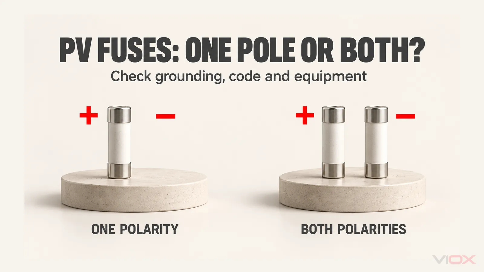
Not always. A PV combiner may use protection in one polarity when the adopted code and equipment design allow it; other projects require fuses in both positive and negative conductors. The decision depends on the grounding arrangement, ground-fault protection, applicable code edition, inverter instructions and the combiner’s documented configuration. A requirement to disconnect both poles does not automatically mean that both poles must contain fuses.
Start by separating three questions: whether the circuit needs overcurrent protection, which conductors require it, and how the circuit will be disconnected for service. A photograph showing two rows of fuse holders cannot answer all three.
Positive Only or Both Poles: A Configuration Decision Table
| Established project condition | What it means for the fuse decision | Cosa deve ancora essere verificato |
|---|---|---|
| The adopted PV rules permit one-polarity overcurrent protection, and the required fault protection and equipment instructions support that arrangement | Single-polarity fusing can be a valid option | Which polarity is used consistently, exact device ratings and the separate disconnect arrangement |
| Applicable equipment instructions or the approved project specification require both-polarity protection | Select an assembly designed and documented for that configuration | Fuse locations, protection of each string, holder compatibility, thermal duty and disconnection |
| A circuit conductor is solidly grounded | Do not independently add a fuse in that conductor merely for symmetry | Grounded-conductor interruption rules and the actual grounding diagram |
| Grounding or the relevant equipment documents are unknown | Neither positive-only nor dual-polarity protection has been justified | Obtain the single-line diagram, adopted rules and exact inverter/combiner instructions |
| The circuit qualifies for an applicable overcurrent-protection exception | The first question may be whether a string fuse is required at all | All current sources, conductor limits and module/equipment protection requirements |
The table is a document-review framework, not a wiring instruction. In particular, permission to use one polarity in one code framework cannot be exported to every IEC-based project.
First Establish Whether String Overcurrent Protection Is Required
PV string fuses commonly address reverse current from parallel strings or other sources into a faulted circuit. The normal operating current of one string is not the only relevant input.
Check the possible current contributions, module maximum overcurrent-protection rating, conductor ampacity, inverter or converter backfeed characteristics and the adopted rules. String count is an input to the PV string overcurrent-protection review, not a universal instruction that every installation with a particular number of strings must have the same fuse arrangement.
When protection is required, fuse rating and fuse location are separate checks. The PV fuse and DC disconnect sizing guide covers the current, voltage and assembly-rating work; adding a negative-side fuse does not remove any of those checks.
DC Negative, Grounded Conductors and PE Are Different
The negative conductor carries operating current. Its minus sign does not identify it as protective earth, a neutral or a conductor that is safe to touch.
Solidly grounded describes an intentional direct grounding arrangement. Functional grounding can involve an impedance or protection arrangement and must be identified from the system documentation. A conductor referenced to earth through a device cannot automatically be treated like a permanently solidly grounded conductor. NEC and IEC terminology should be interpreted within their own definitions.
Protective earth (PE), or the equipment grounding conductor in US terminology, serves a separate protective bonding function. Do not add a PV string fuse in PE, or create a negative-to-PE bond to make a combiner match a familiar diagram.
For an example of the grounded-conductor distinction, the US workplace rule in OSHA 1910.304(f)(1)(ii) limits overcurrent devices that interrupt a grounded conductor unless all circuit conductors open simultaneously, subject to its stated exception. That paragraph addresses circuits rated 600 V or less; it is not a global PV design rule. The same regulation requires an effective, continuous grounding path.
Two independent fuses do not provide the simultaneous opening described by such a rule. Do not assume that fusing both poles is automatically acceptable in a solidly grounded arrangement.
Why Older Transformerless-Inverter Advice Can Be Misleading
A transformer’s presence or absence is not a complete fuse-placement specification. The actual inverter, its ground-fault protection, the applicable rules and the approved array arrangement matter.
There is also an important edition boundary. In his explanation of the 2017 NEC, John Wiles describes the change allowing required PV overcurrent protection in one polarity, provided the single-polarity protection is placed consistently across the PV source and output circuits. The earlier ungrounded-array approach used protection in both conductors. IAEI’s edition-specific explanation shows why an older installation discussion can give a different answer.
Il IAEI review of the 2023 NEC reports that 690.9(C) was renamed PV System DC Circuits while its contents remained the same. These are identified NEC examples, not a claim that every jurisdiction uses that edition or that every modern inverter accepts positive-only fusing.
For a project using the one-polarity option, record the adopted edition, the applicable ground-fault protection and the required polarity consistency. If equipment instructions specify another evaluated arrangement, resolve the discrepancy with the manufacturer and approving authority before selecting the combiner.
IEC-Based Projects and Specifications Need Their Own Check
IEC 62548-1:2023+AMD1:2025 covers PV array design, including DC wiring, electrical protection, switching and earthing. Its public scope does not establish a blanket rule that every array needs fuses in both poles, or that the NEC one-polarity option applies worldwide.
For an IEC-based project, identify the adopted national implementation, applicable amendments, array earthing arrangement, fault-protection design and equipment instructions. Have the responsible designer identify the clauses supporting the proposed fuse configuration. A fuse-link product standard alone does not determine the arrangement of the complete PV installation.
Project specifications can also settle the procurement requirement. For example, ANERT’s published off-grid solar-power-plant specification, sections 11.7 and 11.10, calls for fuses in both positive and negative string inputs; section 11.11 separately calls for simultaneous disconnection of both output polarities. The specification, PDF page 15, illustrates a documented both-polarity requirement; it is not a universal Indian or IEC rule.
This is why two legitimate combiner quotations can contain different numbers of fuse holders. Compare their specified system duties before comparing price or assuming one configuration is incomplete.
Two Fuses Are Not the Same as Two-Pole Isolation
Fuses operate in response to their own current-versus-time conditions. A two-pole switch disconnector uses a defined switching arrangement to disconnect the required conductors. These are different functions.
Il NABCEP 2019 PV Certification Study Guide, page 92, in its comparison of 2014 and 2017 NEC arrangements, shows why this distinction matters: protection in one polarity and disconnection of both conductors can coexist. Read that example within its stated code editions, rather than as a universal installation diagram.
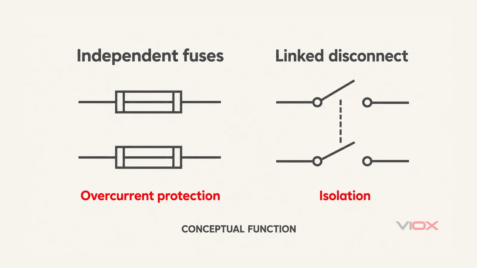
Conceptual functional comparison. Separate fuse elements do not imply common operation. The dashed link in the switching example represents mechanical coordination, not an electrical conductor. These symbols do not show terminals, device internals or an approved installation.
Do not treat a fuse holder as a load-break switch unless its documentation establishes the required switching duty. Two installed fuse-links do not prove that both circuit conductors have opened, and a single operated fuse does not establish a safe service condition.
A qualified service procedure must address the array, other possible sources, the specified isolation points and verification before work. Opening the combiner output does not stop illuminated modules from generating voltage on their side of the isolation boundary.
A Combined Negative Output Fuse Does Not Automatically Protect Every String
Protection location changes the circuit being protected. Suppose several strings connect to a common negative bus. A fuse installed after that bus is at a different location from fuses installed in the individual negative string inputs.
A faulted string can receive reverse current from other connected strings. A protective device after the common connection is not necessarily in the path between those healthy strings and the faulted string. Its presence therefore does not prove the required individual string protection.
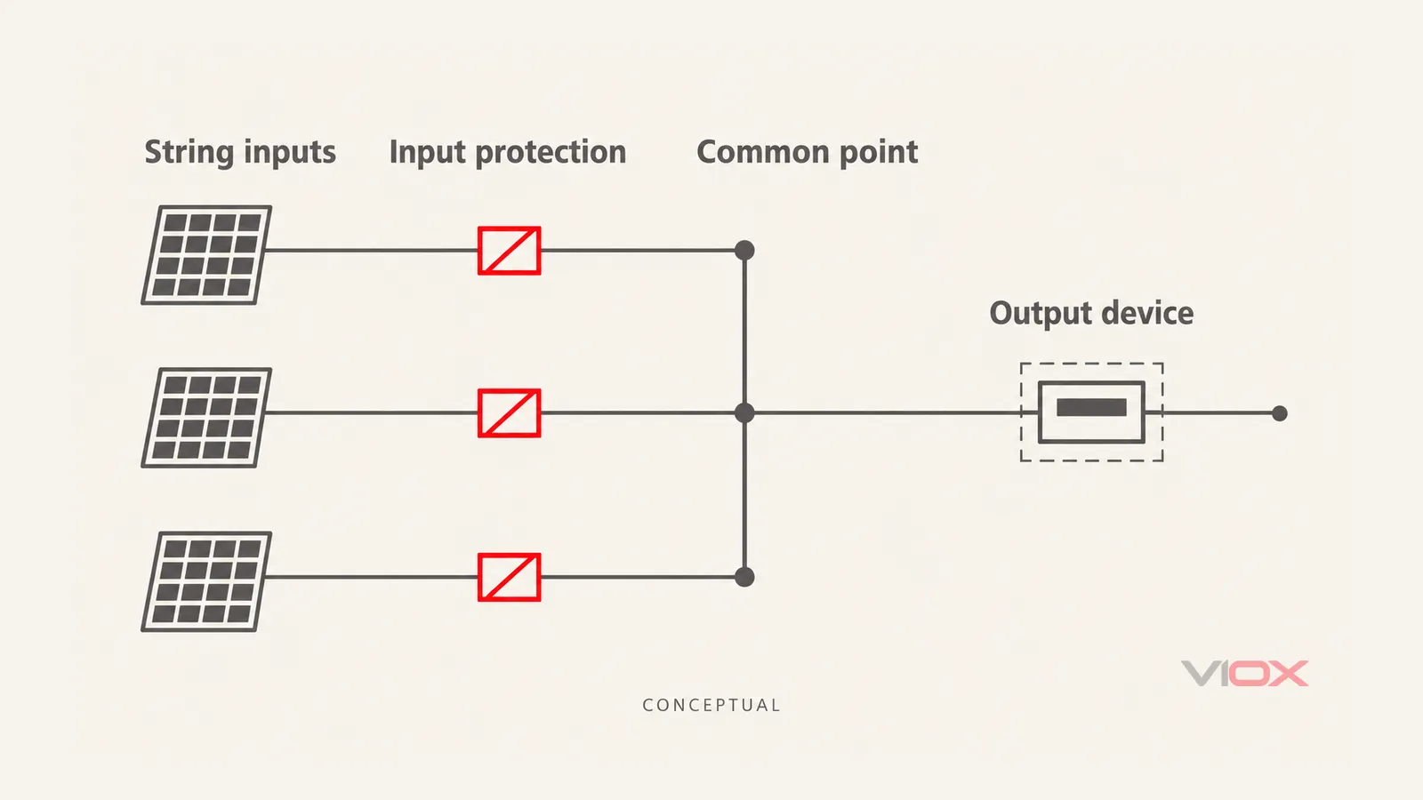
Location comparison only. Individual input devices precede the common point; the shared output device follows it. Lines show system relationships, not positive/negative wiring, actual fault paths or mandatory device quantities. The diagram does not establish that an output fuse is required.
If the design requires each string to have both-polarity overcurrent protection, do not substitute one combined negative-output fuse without an accepted protection design establishing equivalence. Grouped protection arrangements, where permitted, need their own conductor, module and fault-current checks.
Keep different maximum power point tracking (MPPT) inputs within their intended circuit boundaries as well. Do not merge independent inputs simply to make a fuse layout fit. The combiner box wiring guide provides the broader system map; use the exact inverter diagram for the actual arrangement.
Can You Add Negative Fuse Holders to an Existing Combiner?
Only after the revised assembly and system design have been reviewed. Spare DIN-rail space is not evidence that a configuration is suitable.
Adding holders or changing busbars can affect terminal capacity, clearances, conductor routing, temperature rise, touch protection and the enclosure’s evaluated construction. Component ratings alone do not prove the revised assembly is suitable. UL’s field-evaluation guidance explains that modifications may affect existing certification and that modified equipment can require evaluation for its application and location.
Ask the combiner manufacturer whether it provides an approved configuration or documented modification route. If it does not, have the designer and relevant approving authority determine the required assessment or replacement. Avoid both extremes: assuming any alteration is harmless, or asserting that every alteration automatically voids every certification.
Do not remove fuses under load, cut a busbar or move a grounded conductor based on an online layout. A manufacturer’s appropriate factory configuration can be a different proposition from a field modification using individually rated parts.
Put Fuse Placement and Isolation in Separate Specification Fields
Before approving a bill of materials, obtain a record that another reviewer can check. Keep these polarity decisions within the complete combiner box protection design:
| Campo | Evidenze richieste |
|---|---|
| Rule set | Country, adopted code/standard edition, amendments and approved project specification |
| Array and source arrangement | String count, parallel groups, MPPT boundaries and any other fault-current sources |
| Earthing and fault protection | Solid or functional grounding, any ungrounded arrangement, and the actual ground-fault/insulation-monitoring provisions |
| Fuse requirement and placement | Whether OCPD is required, which circuit it protects, and positive-only, negative-only or both-polarity placement as applicable |
| Device and assembly duty | Maximum DC voltage, operating current, module protection limit, interruption duty, holder compatibility and thermal conditions |
| Isolamento | Which conductors open, how they are operated together where required, and the verified switching/isolation ratings |
| Approval and replacement | Exact inverter and combiner drawings, manufacturer instructions, revision and permitted replacement parts |
For example, a specification that says only “two-pole combiner” is incomplete. It may refer to switched conductors, fuse positions or the physical poles of a device. State the protective and switching functions separately.
Utilizzare VIOX combiner box range e fuse/holder range to identify candidate families, then verify the exact model and schematic against those requirements. A product-family description does not establish the required fuse polarity for a particular project.