")
When you open a fuse supplier’s catalog or inspect a fuse marking in an industrial panel, you’ll encounter cryptic letter codes: gG, aM, gPV, gR, aR. These aren’t arbitrary manufacturer designations—they represent the IEC 60269 utilization categories, a systematic classification that defines what type of electrical load each fuse is engineered to protect and under what conditions it operates.
The distinction matters profoundly in practice. A gG general-purpose fuse protecting a cable will fail prematurely if misapplied to motor duty (where aM is correct), allowing damaging overloads to reach the motor winding. An aM motor-protection fuse used on a general distribution circuit provides inadequate overload protection, risking cable damage or fire. A standard AC fuse applied to a photovoltaic DC circuit may fail catastrophically because DC arcs don’t self-extinguish at current zero like AC.
For electrical engineers specifying overcurrent protection, panel builders selecting components, and maintenance electricians replacing fuses, understanding IEC 60269 utilization categories is essential. Yet the classification system remains poorly understood outside specialist circles. This guide explains the IEC 60269 standard structure, decodes the three most common fuse classes—gG (general-purpose), aM (motor protection), and gPV (photovoltaic)—and provides practical selection criteria for matching fuse types to real-world applications.
What is IEC 60269?
IEC 60269 is the international standard governing low-voltage fuses for power-frequency AC circuits up to 1,000 V and DC circuits up to 1,500 V. Published by the International Electrotechnical Commission’s Technical Committee 32/Subcommittee 32B, this standard establishes performance requirements, testing procedures, and classification systems for enclosed current-limiting fuse-links with rated breaking capacities of at least 6 kA.
The standard is structured into seven parts, each addressing specific application domains:
IEC 60269-1 (General Requirements, Edition 5.0, 2024) establishes baseline requirements for all fuse-links, including voltage/current ratings, breaking capacity definitions, time-current characteristic verification, and core testing protocols. This part defines the framework that all subsequent parts build upon.
IEC 60269-2 (Industrial Fuses, Consolidated Edition 2024) provides supplementary requirements for fuses handled and replaced only by authorized persons in industrial applications. It enumerates standardized fuse systems A through K—including NH knife-blade fuses, BS bolted fuses, cylindrical fuses, and others—and specifies performance requirements for industrial duty cycles with high prospective fault currents.
IEC 60269-3 (Household Fuses, Edition 5.0, 2024) covers fuses for operation by unskilled persons in residential and similar applications. It mandates mechanical non-interchangeability features to prevent incorrect rating replacement and ensures safe handling by untrained users.
IEC 60269-4 (Semiconductor Protection, Edition 6.0, 2024) addresses fast-acting fuse-links designed specifically to protect semiconductor devices (rectifiers, thyristors, power transistors) from short-circuit damage, requiring time-current characteristics far faster than general-purpose fuses.
IEC 60269-5 (Application Guidance) provides selection criteria, coordination methods, and practical guidance for engineers specifying fuses across different domains.
IEC 60269-6 (Photovoltaic Systems) establishes supplementary requirements for fuse-links protecting solar PV energy systems, addressing the unique challenges of DC interruption without natural current zeros and the PV operating environment.
IEC 60269-7 (Battery Systems) defines requirements for fuse-links protecting battery energy storage systems, a relatively recent addition reflecting the growth of stationary battery installations.
The standard unifies electrical characteristics and time-current behavior for dimensionally interchangeable fuses, improving system reliability and simplifying maintenance across what were historically fragmented national systems. For every fuse compliant with IEC 60269, manufacturers must verify performance through defined tests: temperature rise and power dissipation, fusing and non-fusing behavior at specified multiples of rated current, time-current characteristic verification (“gates”), and breaking capacity validation.
Understanding the Fuse Classification System
IEC 60269 classifies fuses using a two-letter utilization category code that defines the fuse’s intended application and operational characteristics. This classification system recognizes that protecting a cable from overload imposes fundamentally different requirements than protecting a motor circuit that experiences high starting currents, or a DC photovoltaic string that lacks natural current zeros for arc extinction.
The two-letter code structure works as follows:
First letter indicates the operating range:
- “g” (German: gesamt, “total”) = General-purpose, full-range protection covering both overload and short-circuit regions. The fuse operates from long-time low overcurrents (down into the one-hour blowing region) through high-magnitude short-circuits.
- “a” (German: ausschalten, “partial”) = Partial-range, short-circuit-only protection. The fuse is designed to clear faults but not to operate during normal overloads or motor starting transients. Overload protection must be provided by separate devices (thermal overload relays, motor protection breakers).
Second letter indicates the protected object or application domain:
- “G” = General protection of cables, wires, and distribution circuits
- “M” = Motor circuits and equipment subject to high inrush
- “PV” = Photovoltaic (solar) energy systems with DC operating conditions
- “R” = Semiconductor devices (rectifiers, thyristors, power transistors) requiring ultra-fast response
- “L” = Cables and conductors (largely superseded by “G” in modern practice)
- “Tr” = Transformers
By combining these letters, the utilization category precisely defines both the fuse’s operational behavior and its intended application. gG means general-purpose, full-range protection for cables and distribution. aM means partial-range (short-circuit only) protection for motor circuits. gPV means general-purpose, full-range protection specifically engineered for photovoltaic DC systems.
This classification directly determines the fuse’s time-current characteristic—the curve that plots how long the fuse takes to blow at different overcurrent levels—and its breaking capacity, the maximum fault current it can safely interrupt. Understanding these categories is essential because using the wrong class creates predictable failure modes: inadequate protection, nuisance blowing, or catastrophic arc interruption failure.
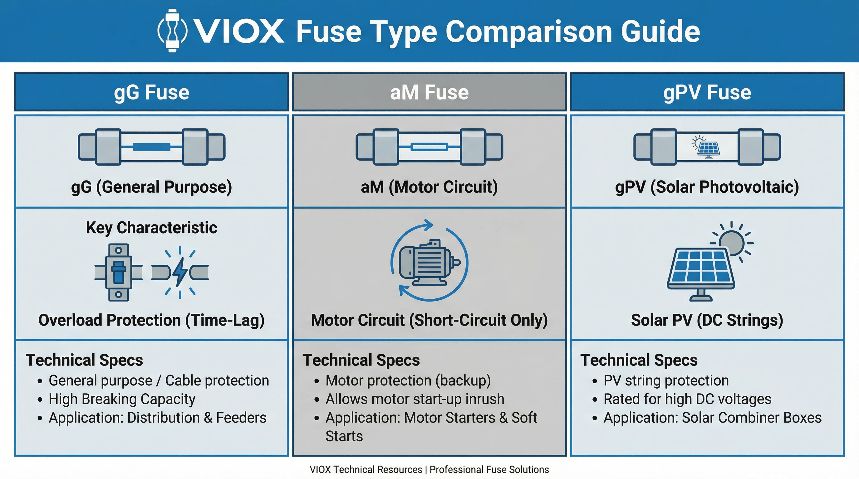
gG Class: General-Purpose Fuses
gG is the default fuse class for cable and conductor protection in both household and industrial installations. The designation breaks down as g (full-range, covering overload and short-circuit) + G (general protection of wires/cables/distribution circuits). This is the fuse you specify when protecting feeders, branch circuits, and distribution systems carrying mixed or predominantly resistive loads.
Characteristics and Time-Current Behavior
A gG fuse provides continuous protection from moderate overloads through catastrophic short-circuits. Its time-current characteristic covers the entire operating spectrum:
- Long-time overload region: At 1.5× rated current (In), a typical gG fuse takes 1–4 hours to blow, providing cable thermal protection without nuisance trips from brief transients.
- Medium overload region: At 5×In, blowing time drops to 2–5 seconds, clearing sustained overloads before cable insulation damage.
- Short-circuit region: At 10×In and above, the fuse clears within 0.1–0.2 seconds, providing fast fault protection.
This graduated response matches cable thermal limits: the fuse tolerates brief harmless transients but clears sustained overcurrents before the conductor reaches damaging temperatures. The time-current curve is verified against standardized “gates” defined in IEC 60269-1, ensuring consistent performance across manufacturers.
Breaking Capacity and Physical Forms
IEC 60269 mandates minimum breaking capacity of 6 kA for all fuse-links in the series. Industrial gG fuses—particularly NH (knife-blade) systems standardized under IEC 60269-2—commonly exceed 100 kA breaking capacity, making them suitable for installations with very high prospective fault currents near transformer secondaries or main distribution points.
gG fuses are available in multiple physical forms:
- NH fuses (DIN-style knife-blade contacts): Sizes 000, 00, 0, 1, 2, 3, 4 covering 2A to 1250A, with ceramic bodies and blade terminals for bolted panel mounting
- Cylindrical fuses (cartridge style): Standard diameters 10×38mm, 14×51mm, 22×58mm for ratings from 1A to 125A, used in fuse holders or DIN-rail bases
- BS bolted fuses (British Standard square-body): Industrial sizes for high-current applications
- Household cartridge fuses per IEC 60269-3: With mechanical coding to prevent incorrect rating replacement
Typical Applications
gG fuses are the workhorse of electrical distribution:
- Feeder protection: Main and branch circuit protection in distribution boards, panelboards, and control cabinets
- Cable protection: Matching fuse rating to cable ampacity to prevent insulation damage from sustained overload
- Lighting circuits: Commercial and industrial lighting distribution (both resistive incandescent and inductive discharge lighting)
- General power distribution: Mixed loads in commercial buildings, manufacturing facilities, and infrastructure
- Transformer primary/secondary protection: Where magnetizing inrush is not excessive
Coordination and Selectivity
For cascaded gG fuses (upstream and downstream in the same circuit), IEC 60269-5 application guidance and manufacturer data establish the 1.6× rule: total selectivity is typically achieved when the upstream fuse rated current is at least 1.6 times the downstream fuse rated current. For other device combinations (gG with circuit breakers, contactors, or other fuse classes), selectivity must be verified by comparing time-current curves and let-through energy (I²t) across the full fault range.
Selection Criteria
Specify gG when:
- The load is predominantly resistive or mixed (lighting, heating, general distribution)
- Full-range overload and short-circuit protection is required in a single device
- The application doesn’t involve high motor starting inrush or specialized DC/PV duty
- The installation conforms to IEC 60269-2 (industrial) or IEC 60269-3 (household) domains
Do not use gG for motor circuits where starting inrush causes nuisance blowing (use aM), or for DC photovoltaic systems where AC-rated fuses may fail to interrupt DC arcs (use gPV).
aM Class: Motor Protection Fuses
aM fuses are engineered specifically for motor circuits and equipment subject to high starting (locked-rotor) currents. The designation breaks down as a (partial-range, short-circuit protection only) + M (motor circuits). Unlike gG fuses that provide full overload protection, aM fuses deliberately tolerate motor starting transients—which can reach 5–8 times motor full-load current—while still providing robust short-circuit clearing.
Why Motor Circuits Need Specialized Fuses
When an induction motor starts, it draws locked-rotor current typically 6–8× its rated full-load current for several seconds until the rotor accelerates to operating speed. A gG fuse sized to the motor’s running current would blow on every start. Oversizing a gG fuse to tolerate starting eliminates overload protection, leaving the motor winding vulnerable to damage from sustained overcurrent.
The aM class solves this dilemma by providing partial-range protection:
- Permits motor starting: The fuse element and time-current characteristic are designed to withstand motor inrush without blowing, even through multiple start cycles.
- Clears short-circuits: Despite tolerating starting currents, the fuse rapidly clears genuine fault currents that exceed motor locked-rotor levels.
- Requires separate overload protection: Because aM fuses don’t operate in the overload region, motor thermal protection must be provided by separate devices (thermal overload relays, motor protection breakers).
This division of labor—aM for fault protection, thermal devices for overload—is standard practice in industrial motor control.
Characteristics and Time-Current Behavior
aM fuses have fundamentally different time-current curves than gG:
- No long-time overload operation: Unlike gG, aM fuses do not intentionally blow at 1.5–2×In. They tolerate sustained currents in the motor starting range without operation.
- Short-circuit clearing: At currents well above motor locked-rotor (typically >10–15×In), the fuse clears rapidly, similar to gG in the fault region.
- Starting duty withstand: The fuse element’s thermal mass and design allow it to absorb the I²t energy of motor starting without damage, verified through testing per IEC 60269-2.
Breaking Capacity and Physical Forms
aM fuses are manufactured in the same physical formats as gG—primarily NH knife-blade and cylindrical cartridge styles—but with different internal element design. Industrial NH aM fuses commonly achieve >100 kA breaking capacity, identical to gG equivalents, because both must interrupt the same prospective fault currents in industrial installations.
Typical Applications
aM fuses are the standard choice for motor protection in industrial control:
- Motor feeders: Main fuses protecting individual motor circuits in motor control centers (MCCs), with downstream contactors and thermal overload relays completing the protection scheme
- Direct-on-line (DOL) starters: Combined with contactors and overloads in starter assemblies for pumps, fans, compressors, and conveyors
- Process equipment: Motors driving industrial machinery where direct starting is used
- HVAC systems: Large compressor and fan motors in commercial/industrial climate control
aM is specified wherever motors are directly started (not soft-started or VFD-controlled) and starting inrush would cause gG nuisance blowing.
Coordination Requirements
Because aM fuses provide only short-circuit protection, coordination with overload devices is mandatory. The complete motor protection scheme typically includes:
- aM fuse: Short-circuit protection (fault clearing)
- Thermal overload relay or motor protection breaker: Overload protection (sustained overcurrent from mechanical overload, single-phasing, etc.)
- Contactor: Switching device for start/stop control
Coordination must ensure the overload device trips before the fuse blows during overload conditions, while the fuse clears before the overload device or contactor is damaged during short-circuit faults. This requires comparing time-current curves and verifying that the overload device’s trip curve sits entirely below the fuse’s melting curve in the overload region.
Selection Criteria
Specify aM when:
- Protecting motor circuits with direct-on-line starting
- Motor starting current would cause nuisance blowing of gG fuses
- Separate thermal overload protection is provided in the control scheme
- The application conforms to IEC 60269-2 industrial motor duty
Do not use aM for general distribution circuits (no overload protection), for cables/feeders requiring full-range protection (use gG), or where motor protection must be provided by the fuse alone (use motor-rated circuit breakers instead).
gPV Class: Photovoltaic Fuses
gPV fuses are specifically engineered for protecting solar photovoltaic energy systems, governed by IEC 60269-6 supplementary requirements. The designation breaks down as g (full-range, covering overload and short-circuit) + PV (photovoltaic systems). These fuses address the unique challenges of DC circuit protection in solar installations—challenges that make standard AC-rated fuses inadequate and potentially dangerous.
Why PV Systems Require Specialized Fuses
DC circuits behave fundamentally differently than AC during fault interruption:
- No natural current zero: AC current crosses zero 100 or 120 times per second (50 Hz or 60 Hz systems), providing natural arc-extinction points when a fuse blows. DC current is continuous—there is no zero crossing. The fuse must actively force arc extinction through physical design.
- High operating voltages: Modern utility-scale PV strings operate at DC voltages up to 1,500 V, far higher than typical AC distribution voltages.
- Reverse current scenarios: In string/array configurations, if one string develops a fault, other parallel strings can back-feed current into the fault through the affected string’s fuse.
- Environmental exposure: PV fuses in combiner boxes are often installed outdoors, subject to temperature extremes, UV exposure, and moisture.
For these reasons, using AC-rated gG or aM fuses in DC PV circuits is unsafe. Only gPV fuses meeting IEC 60269-6 provide verified DC interruption performance.
Characteristics and Time-Current Behavior
gPV fuses provide full-range protection similar to gG, but optimized for the PV operating environment:
- Cable and string protection: The time-current characteristic protects PV cables and string wiring from overload and fault conditions.
- DC-rated breaking capacity: Verified through DC interruption testing per IEC 60269-6, with performance confirmed at system voltage (up to 1,500 V DC).
- Rated for PV duty cycles: PV systems experience unique load profiles—daytime generation with temperature-dependent current, nighttime dormancy, and transient cloud-edge effects.
Physical Design Differences
Compared to equivalent AC fuses, gPV fuses are typically:
- Longer: Increased length provides greater arc interruption distance.
- Specialized fill material: Enhanced arc-quenching sand or other dielectric materials to suppress DC arcs.
- Higher voltage rating: Explicitly rated for DC service up to 1,000 V or 1,500 V.
Typical Applications in Solar Installations
- String protection: Individual fuses protecting each PV string in combiner boxes.
- Array main protection: Main fuses on combiner box outputs feeding inverters.
- DC combiner/distribution: Protection of DC cables and distribution equipment between arrays and inverters.
- Off-grid and battery systems: DC circuit protection in standalone solar installations.
Selection Criteria
Specify gPV when:
- Protecting DC circuits in photovoltaic systems
- Operating at DC voltages from 100 V to 1,500 V
- String/array protection in grid-tied or off-grid solar installations
- Any application where DC current interruption is required in the PV domain
Do not use gG or aM (AC-rated fuses) in PV DC circuits—they lack DC interruption capability and pose safety hazards. Always verify the fuse is explicitly rated for DC service at system voltage.
Key Technical Differences Between gG, aM, and gPV
| Current Level | gG Behavior | aM Behavior | gPV Behavior |
| 1.5×In (overload) | Blows in 1–4 hours | Tolerates indefinitely | Blows in 1–4 hours |
| 5×In (sustained overload) | Blows in 2–5 seconds | Tolerates or slow response | Blows in 2–5 seconds |
| 10×In (short-circuit) | Blows in 0.1–0.2 seconds | Blows in 0.1–0.2 seconds | Blows in 0.1–0.2 seconds |
The curves show that gG and gPV operate across the full spectrum, while aM “ignores” the overload region to permit motor starting.
Practical Selection Guide: Matching Fuse Class to Application
Step 1: Identify the Load Type and Electrical Characteristics
- Cables, feeders, general distribution circuits with resistive or mixed loads → Consider gG
- Motor circuits with direct-on-line starting and high locked-rotor current → Consider aM
- Photovoltaic DC circuits in solar installations → Require gPV
- Semiconductor devices (rectifiers, thyristors, inverters) → Consider gR/aR
Step 2: Calculate Steady-State and Transient Currents
Calculate load currents and inrush (motor starting, etc.). For motors, use aM fuses sized 1.5–2.5×FLC to withstand starting. For general circuits, match gG to cable ampacity.
Step 3: Verify Voltage and Breaking Capacity
Ensure voltage ratings (AC vs DC) and breaking capacity (Icn/Icu) exceed system parameters.
Step 4: Check Coordination and Selectivity
Apply 1.6× rule for gG selectivity. Coordinate aM fuses with overload relays.
Common Selection Scenarios
Scenario 1: 50 kW / 400V three-phase distribution feeder: Load is mixed distribution → Use gG.
Scenario 2: 22 kW / 400V three-phase induction motor, DOL start: High inrush current → Use aM + Overload Relay.
Scenario 3: Solar PV string, 450V DC: DC circuit with reverse current risk → Use gPV.
Conclusion
IEC 60269 utilization categories—gG, aM, and gPV—provide a systematic framework for classifying low-voltage fuses by their intended application and operational characteristics. These designations aren’t marketing terms; they define verified performance requirements tested and documented in the international standard.
gG (general-purpose) fuses provide full-range protection for cables, feeders, and distribution circuits, covering overload through short-circuit. They’re the default choice for most electrical distribution applications in household and industrial settings.
aM (motor protection) fuses offer partial-range protection designed specifically for motor circuits, tolerating high locked-rotor starting currents while clearing short-circuit faults. They must be paired with separate thermal overload protection to form a complete motor protection scheme.
gPV (photovoltaic) fuses address the unique demands of DC solar systems—extended fuse bodies and specialized arc-quenching materials to interrupt DC currents without natural zero crossings, rated for DC voltages up to 1,500 V.
For electrical engineers, panel builders, and maintenance personnel, understanding these distinctions is essential to reliable system operation. Misapplication creates predictable consequences: gG fuses on motor duty cause nuisance trips; aM fuses on distribution circuits provide inadequate overload protection; AC-rated fuses on DC PV circuits risk catastrophic interruption failure.
Proper selection requires analyzing load characteristics (resistive/motor/DC), calculating steady-state and transient currents, verifying voltage and breaking capacity ratings, ensuring coordination with other protective devices, and accounting for environmental conditions. The two-letter utilization category code on every IEC 60269 fuse defines the tested duty and the conditions under which published ratings apply.
VIOX Electric manufactures low-voltage fuses engineered to IEC 60269 standards across gG, aM, and gPV classes, with comprehensive technical documentation and application support. For specification guidance, coordination studies, or technical consultation on your overcurrent protection requirements, contact VIOX’s engineering team.
Specify the right fuse class for reliable protection. Contact VIOX Electric to discuss your IEC 60269 fuse requirements.
