
Why Ground-Mount Solar Systems Demand Superior Electrical Design
Ground-mount solar installations present a unique electrical challenge that separates amateur installations from professional-grade systems: distance. Unlike rooftop arrays where the inverter sits 20-30 feet away, ground-mount systems often require 100-300 feet of DC cable runs from the array to the building. This distance introduces two critical design considerations that can make or break system performance: voltage drop and overcurrent protection.
Every foot of cable between your solar array and inverter acts as resistance, stealing watts from your energy harvest. Simultaneously, longer cable runs increase fault current risks, making proper fuse sizing not just a code requirement but a fire prevention necessity. This guide provides electrical contractors and solar installers with the calculation methods, NEC-compliant specifications, and practical workflows needed to design safe, efficient ground-mount PV systems.
Understanding DC Voltage Drop in Long Cable Runs
The Physics of Power Loss
Voltage drop isn’t theoretical—it’s money leaving your system as heat. When DC current flows through copper conductors, the wire’s resistance converts electrical energy into thermal energy following Ohm’s Law. For ground-mount installations, this matters because:
- A 150-foot cable run has six times the resistance of a 25-foot rooftop run
- Voltage drop compounds with current; doubling array size can quadruple losses if wire isn’t upsized
- DC systems lack the voltage transformation advantages of AC distribution
NEC Voltage Drop Standards
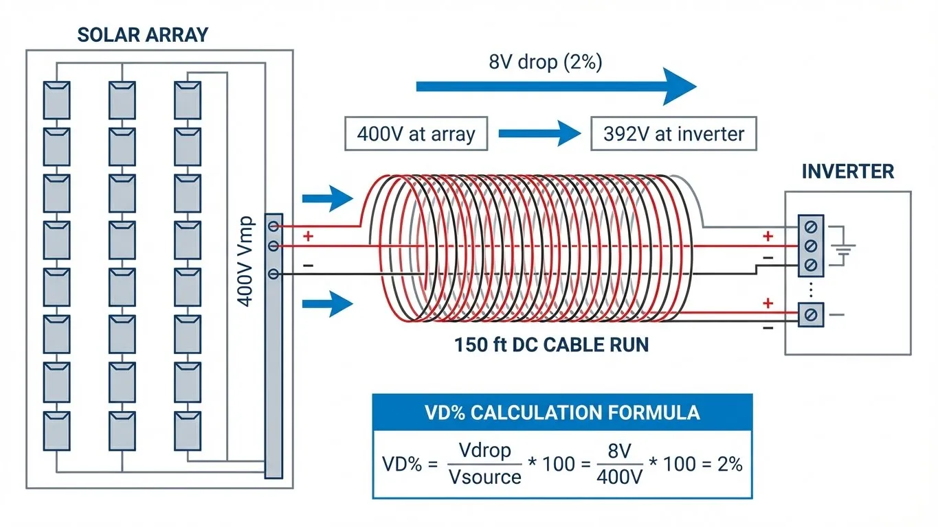
While the National Electrical Code (NEC) doesn’t mandate specific voltage drop limits for safety, NEC 210.19(A) Informational Note No. 4 recommends keeping voltage drop below 2% for DC circuits. The solar industry has adopted this as a design standard for PV source circuits (array to combiner) and PV output circuits (combiner to inverter).
Why 2%? Because voltage drop directly reduces Maximum Power Point Tracking (MPPT) efficiency. If your inverter expects 400V DC but receives 392V due to cable losses, the MPPT algorithm struggles to maintain optimal operating point, costing you 3-5% annual energy production.
Voltage Drop Calculation Formula
The standard formula for DC voltage drop is:
VD% = (2 × L × I × R) / V × 100
Where:
- VD% = Percentage voltage drop
- L = One-way cable length (feet)
- I = Current in amperes (typically string Imp or array total current)
- R = Conductor resistance per 1,000 feet at 75°C (from NEC Chapter 9, Table 8)
- V = System voltage (Vmp for array, Voc for code compliance)
- 2 = Accounts for both positive and negative conductors (round-trip distance)
Practical Example:
You have a 10kW ground-mount array, 120 feet from the inverter, operating at 400V with 25A current. Using 10 AWG copper wire (R = 1.24Ω per 1,000ft at 75°C):
VD% = (2 × 120 × 25 × 1.24) / (400 × 1,000) × 100 = 1.86% ✓ (Acceptable)
If you used 12 AWG instead (R = 1.98Ω per 1,000ft):
VD% = (2 × 120 × 25 × 1.98) / (400 × 1,000) × 100 = 2.97% ✗ (Exceeds 2% limit)
Voltage Drop Reference Table
| AWG Size | Resistance (Ω/1000ft @ 75°C) | Max Distance for 2% VD Drop (25A @ 400V) | Max Distance for 3% VD Drop (25A @ 400V) |
|---|---|---|---|
| 6 AWG | 0.491 | 326 ft | 489 ft |
| 8 AWG | 0.778 | 206 ft | 308 ft |
| 10 AWG | 1.24 | 129 ft | 194 ft |
| 12 AWG | 1.98 | 81 ft | 121 ft |
| 14 AWG | 3.14 | 51 ft | 76 ft |
Table assumes copper conductors, 400V system voltage, 25A current. For different parameters, use the formula above.
Cable Sizing for Ground-Mount Arrays: Balancing Ampacity and Voltage Drop
The Dual-Constraint Problem
Selecting wire gauge for ground-mount PV installations requires satisfying two independent criteria:
- Ampacity: Wire must handle maximum current without overheating (NEC 690.8)
- Voltage Drop: Wire must limit resistive losses to ≤2% for efficiency
The mistake installers make? Choosing wire based solely on ampacity tables, then discovering voltage drop exceeds acceptable limits after installation.
Step 1: Calculate Minimum Ampacity Requirement
Per NEC 690.8(A)(1), PV source circuit conductors must be sized at 125% of the module’s short-circuit current (Isc) before applying any correction factors:
Minimum Ampacity = 1.25 × Isc
For parallel strings, multiply by the number of strings. Additionally, NEC 690.8(B)(1) requires PV output circuit (combiner to inverter) conductors to handle 125% of the combined current.
Example: Three parallel strings, each with Isc = 11A:
- Combined Isc = 33A
- Minimum conductor ampacity = 33A × 1.25 = 41.25A
- From NEC Table 310.16 (75°C column), 8 AWG copper = 50A ampacity ✓
Step 2: Apply Temperature Correction Factors
Ground-mount installations expose conductors to extreme temperatures. If ambient temperature exceeds 30°C (86°F), you must derate ampacity using NEC Table 310.15(B)(1):
| Ambient Temperature | Correction Factor (75°C insulation) |
|---|---|
| 30°C (86°F) | 1.00 |
| 40°C (104°F) | 0.88 |
| 50°C (122°F) | 0.75 |
| 60°C (140°F) | 0.58 |
For our 41.25A example in a 50°C environment:
- Required ampacity after correction = 41.25A / 0.75 = 55A
- 8 AWG (50A) is now insufficient; must upgrade to 6 AWG (65A) ✓
Step 3: Verify Voltage Drop
Using our corrected 6 AWG wire for a 150-foot run at 33A and 400V:
VD% = (2 × 150 × 33 × 0.491) / (400 × 1,000) × 100 = 1.21% ✓ (Excellent)
Cable Sizing Decision Matrix
| Array Current | Distance | Minimum AWG (Ampacity Only) | Recommended AWG (2% VD Limit) | VIOX Cable Lug Compatibility |
|---|---|---|---|---|
| 15-20A | <100 ft | 12 AWG | 10 AWG | CL-10 Series |
| 20-30A | <150 ft | 10 AWG | 8 AWG | CL-8 Series |
| 30-45A | <200 ft | 8 AWG | 6 AWG | CL-6 Series |
| 45-65A | <250 ft | 6 AWG | 4 AWG | CL-4 Series |
| 65-85A | <300 ft | 4 AWG | 2 AWG | CL-2 Series |
Assumes 400V system, 50°C ambient, copper USE-2 or PV wire. Always verify with voltage drop calculation.
Fuse Selection and Sizing for Ground-Mount PV Systems
Why Fuses Are Non-Negotiable in Parallel String Configurations
In ground-mount installations with multiple parallel strings, fuses provide the primary overcurrent protection against three fault scenarios:
- Line-to-Line Faults: Short circuit between positive and negative conductors
- Ground Faults: Unintentional path to earth ground
- Reverse Current: When one string backfeeds current into a shaded or damaged string
NEC 690.9(A) states: “Solar photovoltaic systems shall be protected against overcurrent.” Fuses serve as the sacrificial element that opens the circuit before cable insulation melts or modules suffer catastrophic failure.
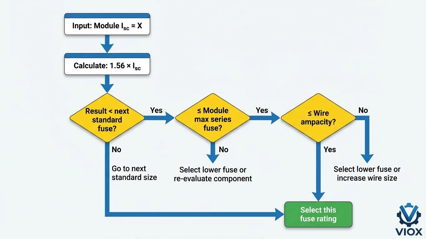
The 1.56× Isc Sizing Rule Explained
The cornerstone of PV fuse sizing is the 1.56 multiplier applied to module short-circuit current. This comes from NEC 690.8(A)(1) which requires:
Minimum Fuse Rating ≥ 1.56 × Isc (per string)
Where does 1.56 come from?
- 1.25 = Safety factor for continuous current
- 1.25 = Additional factor for irradiance conditions exceeding Standard Test Conditions (STC)
- 1.25 × 1.25 = 1.5625 (rounded to 1.56)
Example Calculation:
Module datasheet shows Isc = 11.5A
- Calculate minimum fuse rating: 11.5A × 1.56 = 17.94A
- Select next standard fuse size: 20A (standard ratings: 10A, 15A, 20A, 25A, 30A)
- Verify against module’s maximum series fuse rating (from datasheet): If listed as 25A, then 20A ✓
Critical Check: The selected fuse must also be ≤ conductor ampacity. If your 10 AWG wire is rated 30A, a 20A fuse provides proper wire protection ✓
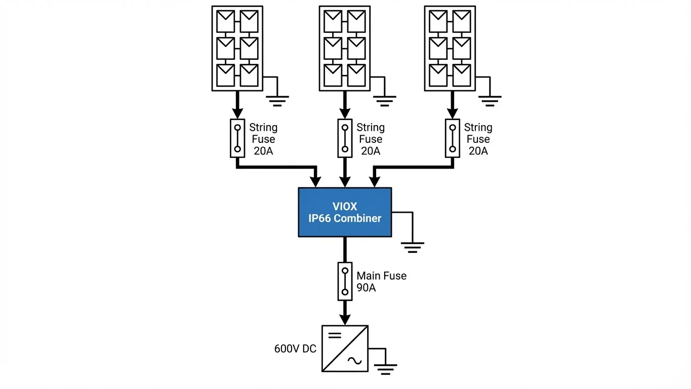
String Fuse vs. Combiner Output Fuse
Ground-mount systems typically require two levels of overcurrent protection:
String-Level Fuses (Inside Combiner Box):
- Purpose: Protect individual string conductors from reverse current
- Location: One fuse per string positive conductor
- Sizing: 1.56 × Isc per string
- Example: For Isc = 11A, use 15A gPV-rated DC fuse
Combiner Output Fuse (Between Combiner and Inverter):
- Purpose: Protect main DC feeder cable
- Location: After parallel connection point
- Sizing per NEC 690.8(B)(1): 1.25 × (sum of all string Isc values)
- Example: 6 strings × 11A = 66A combined; 66A × 1.25 = 82.5A → use 90A or 100A fuse
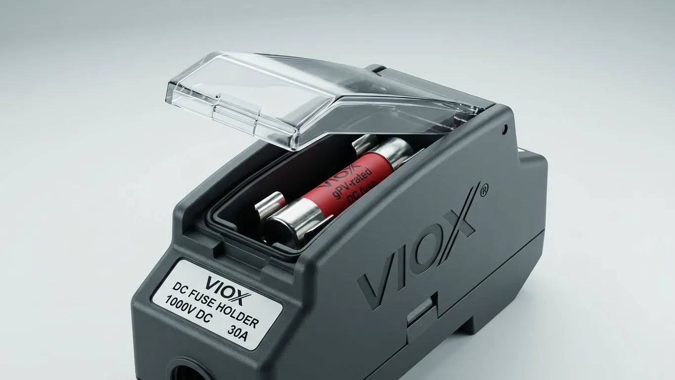
VIOX Fuse Holder Specifications for Ground-Mount Applications
VIOX manufactures gPV-rated DC fuse holders specifically engineered for photovoltaic applications:
| Product Series | Voltage Rating | Current Rating | IP Rating | Features |
|---|---|---|---|---|
| VIOX FH-15DC | 1000V DC | 15-30A | IP66 | Touch-safe, LED fault indicator |
| VIOX FH-30DC | 1000V DC | 30-60A | IP66 | Quick-release mechanism, dual pole |
| VIOX FH-100DC | 1500V DC | 60-125A | IP66 | Integrated busbar, suitable for 1500V systems |
All VIOX fuse holders meet UL 248-14 (for gPV fuses) and IEC 60947-3 standards, ensuring compatibility with major fuse manufacturers (Mersen, Littelfuse, Bussmann).
Fuse Selection Quick Reference
| Module Isc | Minimum Fuse Rating (1.56× Isc) | Standard Fuse Size | Max Conductor Protection |
|---|---|---|---|
| 9A | 14.0A | 15A | 12 AWG (20A) |
| 11A | 17.2A | 20A | 10 AWG (30A) |
| 13A | 20.3A | 25A | 10 AWG (30A) |
| 15A | 23.4A | 25A | 8 AWG (40A) |
| 18A | 28.1A | 30A | 8 AWG (40A) |
Always verify module datasheet “Maximum Series Fuse Rating” before final selection.
Practical Design Workflow: Step-by-Step Checklist
Follow this systematic approach to design compliant, efficient ground-mount PV electrical systems:
Phase 1: Data Collection
- Obtain module datasheet (Voc, Vmp, Isc, Imp, temperature coefficients)
- Measure physical distance from array to inverter entry point
- Determine ambient temperature range (use local weather data for worst-case)
- Identify system voltage (12V, 24V, 48V off-grid; 300-600V grid-tied)
- Count total strings in parallel configuration
Phase 2: Cable Sizing
- Calculate minimum ampacity: 1.25 × Isc × number of parallel strings
- Apply temperature derating factor (NEC Table 310.15(B)(1))
- Select preliminary AWG size from NEC Table 310.16
- Calculate voltage drop using formula: VD% = (2 × L × I × R) / V × 100
- If VD > 2%, upsize conductor and recalculate
- Verify final AWG meets both ampacity AND voltage drop criteria
Phase 3: Fuse Specification
- String fuse sizing: 1.56 × Isc per string → select next standard size
- Verify fuse ≤ conductor ampacity (e.g., 20A fuse ≤ 30A conductor)
- Verify fuse ≤ module maximum series fuse rating (from datasheet)
- Combiner output fuse: 1.25 × (sum of all string Isc) → select next standard size
- Specify gPV-rated DC fuses with interrupt rating ≥ available fault current
Phase 4: Component Selection
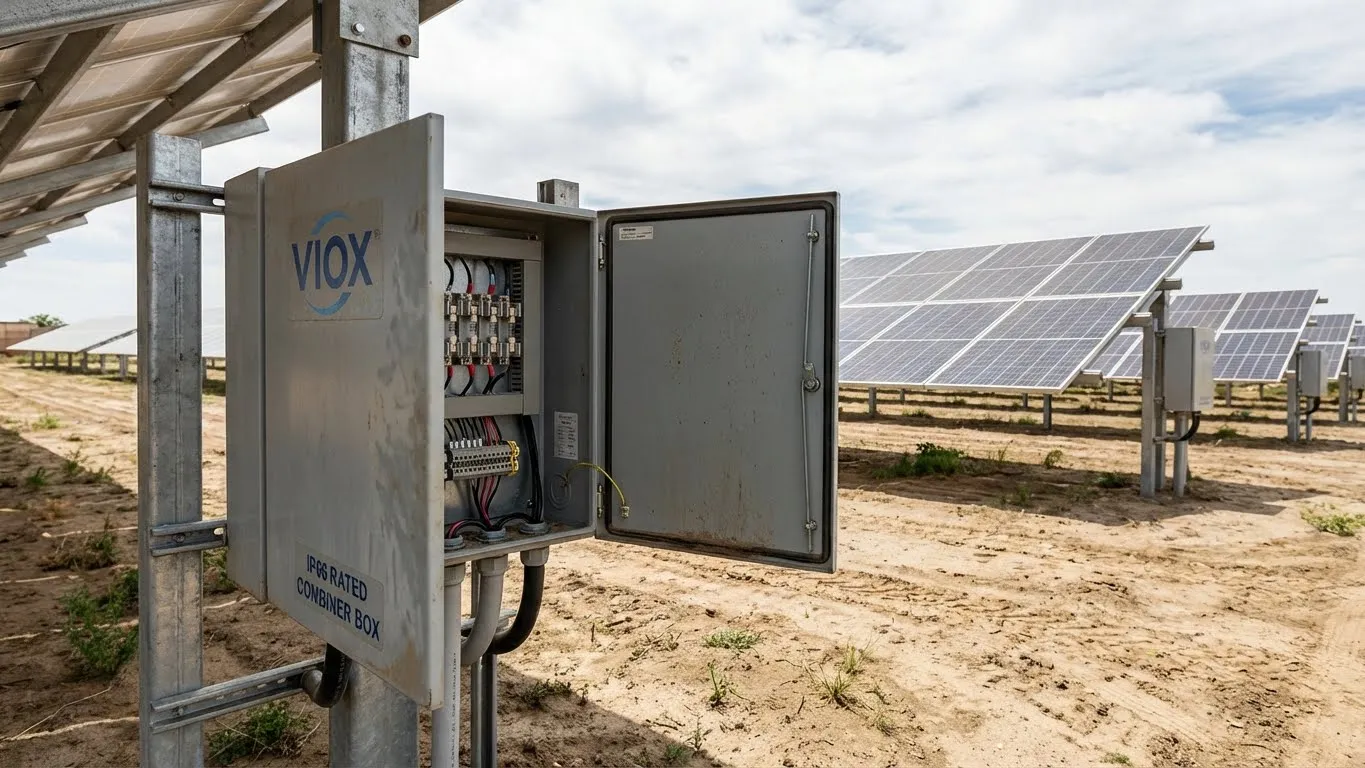
- Select VIOX IP66-rated combiner box (size based on string count)
- Specify VIOX fuse holders (voltage and current ratings)
- Select DC-rated disconnect switch (must handle system Voc)
- Specify cable lugs compatible with AWG size (VIOX CL-series)
- Include surge protection device (SPD) if required by local code
Common Design Mistakes to Avoid
| Mistake | Consequence | Solution |
|---|---|---|
| Sizing wire by ampacity only | Excessive voltage drop (>3%), MPPT inefficiency | Always calculate VD%; prioritize VD limits over ampacity |
| Using AC-rated fuses in DC circuits | Fuse fails to interrupt DC arc; fire hazard | Specify gPV-rated fuses (UL 248-14 listed) |
| Ignoring temperature derating | Wire overheats in summer; code violation | Apply NEC Table 310.15(B)(1) correction factors |
| Mixing aluminum and copper conductors | Galvanic corrosion at connections | Use copper throughout OR use anti-oxidant compound with aluminum |
| Oversizing fuses “to be safe” | Wire insulation melts before fuse blows | Fuse rating must be ≤ wire ampacity |
Design Parameter Quick Reference
| Parameter | Typical Range | Code Reference | VIOX Product Line |
|---|---|---|---|
| Voltage Drop Limit | ≤2% (3% maximum) | NEC 210.19(A) Note 4 | N/A |
| String Fuse | 15-30A (residential) | NEC 690.9 | FH-15DC, FH-30DC |
| Combiner Fuse | 60-125A (residential) | NEC 690.8(B) | FH-100DC |
| Cable AWG | 6-10 AWG (typical) | NEC 310.16 | CL-6, CL-8, CL-10 lugs |
| Combiner Box Rating | IP65 minimum (IP66 recommended) | NEC 690.31(E) | CB-6, CB-12, CB-18 series |
Frequently Asked Questions
Q: Do I need fuses if I only have two solar panel strings in parallel?
A: According to NEC 690.9(A) Exception, fuses are not required when only two strings connect in parallel, because the maximum reverse current from one string cannot exceed the conductor’s ampacity. However, many professional installers add fusing anyway for three reasons: (1) easier troubleshooting and isolation, (2) future expansion capability without rewiring, and (3) additional protection against ground faults. VIOX recommends fusing all parallel configurations in ground-mount systems due to longer cable runs and higher fault current exposure.
Q: Can I use standard AC fuses in my DC solar system?
A: Never use AC-rated fuses in DC applications. DC current maintains constant polarity, creating sustained electric arcs that AC fuses cannot interrupt safely. PV systems require gPV-rated fuses (UL 248-14 listed) specifically designed for DC photovoltaic applications. These fuses have specialized arc-quenching materials and higher interrupt ratings (typically 20kA-50kA at 1000V DC). VIOX fuse holders are engineered exclusively for gPV fuses and meet IEC 60947-3 DC-PV2 utilization category.
Q: How do I calculate voltage drop if my array has multiple strings at different distances?
A: Calculate voltage drop for the longest cable path in your system—this becomes your worst-case scenario. For complex configurations with intermediate combiner boxes, sum the voltage drops of each segment: Array → Intermediate Combiner (VD1%) + Intermediate Combiner → Main Combiner (VD2%) + Main Combiner → Inverter (VD3%). Total VD% should remain ≤2%. If strings vary significantly in distance, consider multiple combiner boxes closer to array sections rather than one centralized combiner.
Q: What’s the difference between conductor ampacity and fuse rating?
A: Conductor ampacity (from NEC Table 310.16) is the maximum continuous current a wire can carry without insulation damage. Fuse rating is the current level at which the fuse will blow within a specified time. Key relationship: Fuse rating must be ≤ conductor ampacity to protect the wire. Example: 10 AWG copper = 30A ampacity. You could use a 25A fuse (protects wire) but never a 40A fuse (wire would overheat before fuse blows).
Q: Do I need to upsize my ground wire when I upsize current-carrying conductors?
A: Per NEC 250.122, equipment grounding conductors (EGC) must be sized according to the overcurrent protection device rating, not the conductor size. However, if you upsize conductors solely for voltage drop reasons, NEC 250.122(B) requires proportional EGC upsizing. Use the same AWG for ground wire as your current-carrying conductors, or reference NEC Table 250.122. For ground-mount arrays, VIOX recommends minimum #6 AWG bare copper for equipment grounding, consistent with industry best practices for lightning protection.
Q: How often should I replace fuses in my solar combiner box?
A: Properly sized fuses should never blow under normal operating conditions—they only activate during fault events. Do not replace fuses on a schedule; instead, perform annual inspections checking for: (1) corrosion on fuse end caps, (2) discoloration indicating overheating, (3) loose connections in fuse holder. If a fuse blows, always investigate the root cause (damaged module, ground fault, reverse current) before replacement. VIOX fuse holders include LED fault indicators to identify blown fuses without removal.
Q: Can I use the same cable for a 400V system and a 1000V system?
A: No. Cable voltage rating must meet or exceed system maximum open-circuit voltage (Voc). Standard PV wire is rated 600V or 1000V, while USE-2 cable is typically 600V. For systems approaching 600V Voc, you must use 1000V-rated cable. Additionally, NEC 690.7 requires calculating maximum circuit voltage using temperature-corrected factors (voltage increases in cold weather). Always verify cable insulation voltage rating matches or exceeds your array’s cold-weather Voc. VIOX cable lugs specify compatible voltage ratings—use the CL-HV series for systems >600V.
Partner With VIOX for Ground-Mount Excellence
Designing ground-mount solar electrical systems demands precision in three areas: voltage drop mitigation, conductor sizing, and overcurrent protection. The calculations outlined in this guide represent industry-standard methodology aligned with NEC Article 690 requirements.
VIOX Electric manufactures the complete electrical Balance of System (BoS) for ground-mount installations: IP66-rated combiner boxes, gPV DC fuse holders, 1000V-1500V cable lugs, and DC-rated disconnect switches. Our engineering team provides technical support for complex array configurations, and all products meet UL/IEC international standards.
Download our Ground-Mount BoS Product Catalog or contact VIOX technical sales for project-specific component recommendations.
VIOX Electric – Powering Solar Innovation Since 2008 | [Product Catalog] | [Technical Support] | [Distributor Network]
