Earthing systems define how a low-voltage electrical network connects its power source, exposed metal parts, protective conductors, and the physical earth. The three main IEC earthing arrangements are TN, TT، و فناوری اطلاعات. They all aim to reduce electric shock and fire risk, but they do it in different ways.
The short answer:
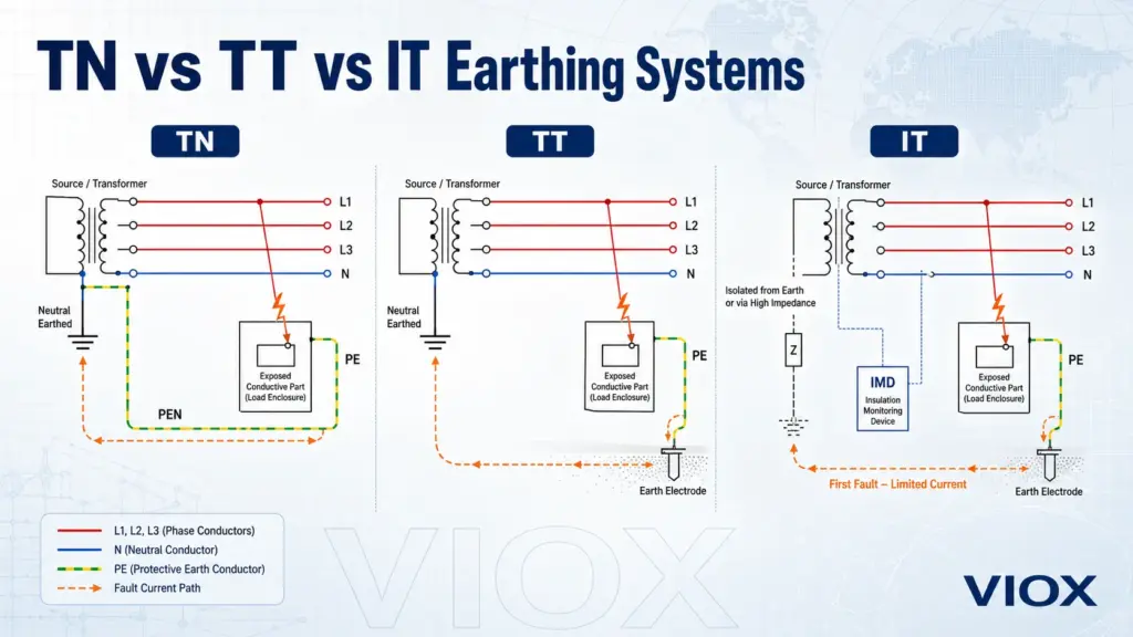
- TN systems use a protective conductor connected back to the supply source. Earth-fault current usually returns through a metallic path, so fault current is relatively high.
- سیستمهای TT use a local earth electrode at the installation. Earth-fault current returns through the soil, so fault current is often lower and residual current devices (RCDs) become essential.
- سیستمهای فناوری اطلاعات isolate the supply from earth or connect it through high impedance. The first earth fault produces limited current, allowing continuity of operation, but insulation monitoring is required.
These differences explain why countries, utilities, factories, hospitals, mines, data centers, and residential installations do not all ground low-voltage networks in the same way.
What Do TN, TT, and IT Mean?
The IEC earthing code uses letters to describe two relationships:
- The relationship between the power source and earth.
- The relationship between exposed conductive parts and earth.
| Letter | معنی | تفسیر عملی |
|---|---|---|
| T | Terra, direct connection to earth | A point of the source or installation is directly earthed |
| من | Isolated or impedance-earthed source | The source is not directly earthed, or is earthed through high impedance |
| ن | Exposed conductive parts connected to source earth | Protective conductors return to the earthed supply point |
| S | Separate neutral and protective conductors | N and PE are separate conductors |
| سی | Combined neutral and protective conductor | Neutral and protective earth functions are combined in a PEN conductor |
That gives the common system families:
- TN-S
- TN-C
- TN-C-S
- TT
- فناوری اطلاعات
The letters look simple, but the protection behavior is very different. A breaker, RCD, SPD, neutral bar, PE bar, or grounding electrode can only be selected correctly when the earthing system is understood.
TN-S, TN-C, and TN-C-S Explained
الف TN earthing system has one point of the supply source directly earthed. The exposed conductive parts of the installation are connected back to that earthed source point through protective conductors.
In practical terms, a TN system provides a metallic earth-fault return path. Because the fault loop impedance is usually low, earth-fault current can be high enough to operate fuses, miniature circuit breakers (MCBs), molded case circuit breakers (MCCBs), or other overcurrent protective devices.
(رایج در اروپا): نول به طور قابل اعتمادی در ترانسفورماتور به زمین متصل است. یک 1P+N معمولاً برای ایزولاسیون در طول تعمیر و نگهداری کافی است.
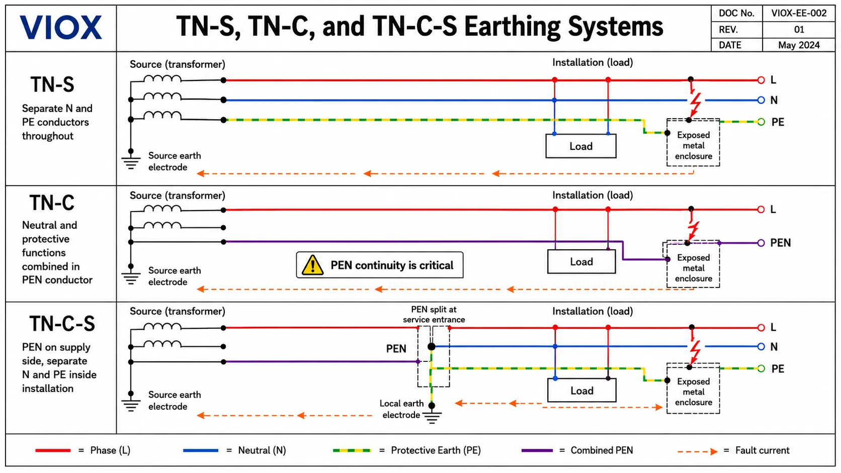
در یک TN-S system, the neutral conductor (N) and protective earth conductor (PE) remain separate throughout the system.
Transformer neutral earthed
N conductor: carries normal return current
PE conductor: carries fault current only
TN-S is attractive because neutral current and protective earth current are separated. This reduces the risk of normal load current flowing on exposed metalwork or protective bonding paths.
Typical characteristics:
- Separate N and PE conductors.
- Metallic fault-current return path.
- Overcurrent protective devices can often clear earth faults if loop impedance is low enough.
- RCDs may still be used for additional protection, special locations, or socket circuits depending on local code.
- Often preferred where electromagnetic compatibility, protective conductor integrity, or sensitive equipment matters.
TN-C System
در یک TN-C system, the neutral and protective earth functions are combined in a single PEN conductor throughout the system.
This arrangement can save conductor material in distribution networks, but it creates important safety limitations. Because the PEN conductor carries normal neutral current and also acts as the protective conductor, it must not be casually interrupted or switched. If a PEN conductor becomes open or high-resistance, exposed conductive parts can rise to dangerous voltage.
Important boundary: TN-C is not the same as TN-C-S. In TN-C, the neutral and protective functions remain combined as PEN. Once the PEN is separated into N and PE, the downstream part is no longer TN-C; it becomes TN-C-S or TN-S depending on the arrangement.
Typical characteristics:
- Uses a combined PEN conductor.
- Not suitable for all parts of modern low-voltage installations.
- RCDs cannot be applied in the TN-C portion in the normal way because neutral and protective earth are combined.
- PEN continuity is safety-critical.
TN-C-S System
در یک TN-C-S system, the supply network uses a combined PEN conductor for part of the system, then separates it into distinct neutral (N) and protective earth (PE) conductors at the installation origin or service equipment.
This arrangement is known in some countries as PME (Protective Multiple Earthing) or MEN (Multiple Earthed Neutral).
Supply side: combined PEN
Installation side after split: separate N and PE
TN-C-S is widely used because it provides a low-impedance fault path without requiring every installation to rely only on its own earth electrode. However, the main engineering concern is PEN failure. If the PEN conductor is broken upstream of the split point, the installation’s protective earth can rise toward line voltage.
Typical characteristics:
- Common in many public low-voltage distribution networks.
- Low fault-loop impedance compared with TT.
- Efficient fault clearing with correctly selected protection.
- Requires strict rules for PEN conductor continuity, bonding, and special locations.
- Broken PEN risk must be considered, especially for outdoor metalwork, EV charging, farms, marinas, and similar installations.
برای تفاوتهای حفاظتی در سطح دستگاه، راهنمای VIOX در مورد RCD vs MCB توضیح میدهد که چرا حفاظت در برابر جریان اضافه و حفاظت در برابر جریان نشتی یکسان نیستند.
تشریح سیستم اتصال زمین TT
در یک سیستم اتصال زمین TT, ، منبع تغذیه دارای یک نقطه است که مستقیماً به زمین متصل شده است، اما بخشهای رسانای در دسترس تأسیسات به یک الکترود زمین محلی مستقل از زمین منبع تغذیه متصل میشوند.
نول منبع تغذیه: متصل به زمین توسط شرکت برقتفاوت کلیدی با سیستم TN در مسیر جریان خطا است. در سیستم TT، حلقه خطای زمین شامل مقاومت الکترود محلی و مسیر خاک تا منبع است. این امپدانس معمولاً بسیار بالاتر از مسیر بازگشت فلزی PE است، بنابراین جریان خطای زمین ممکن است برای قطع سریع فیوز یا کلید مینیاتوری (MCB) بسیار کم باشد.
به همین دلیل است که RCD protection is central to TT systems. The RCD detects residual current imbalance and disconnects the circuit even when the earth-fault current is not high enough to operate an overcurrent device.
TT System Strengths
- Does not rely on the utility’s protective earth conductor.
- Avoids some broken-PEN risks associated with TN-C-S.
- Useful where the utility cannot provide a reliable TN earthing facility.
- Common in rural, overhead-line, temporary, or certain public distribution situations.
TT System Challenges
- Earth electrode resistance matters.
- RCD selection and coordination are critical.
- Surge protection design must consider the local earth path.
- High leakage-current equipment can create nuisance tripping if circuits are not divided properly.
- Inspection and testing of the earth electrode become important maintenance tasks.
For a practical safety-language bridge, see VIOX’s article on اتصال به زمین در مقابل GFCI در مقابل حفاظت از نوسانات.
IT Earthing System Explained
در یک IT earthing system, the supply source is isolated from earth or connected to earth through a high impedance. Exposed conductive parts of the installation are still earthed, but the source itself is not solidly earthed like in TN or TT.
The main purpose of IT is service continuity. During the first earth fault, the fault current is limited because there is no low-impedance return path to the source. Instead of immediately disconnecting the circuit, an insulation monitoring device (IMD) detects the first fault and alarms.
First earth fault: limited current, alarm by IMD
Second earth fault: dangerous condition, must be cleared
Where IT Systems Are Used
IT systems are not normally the default for ordinary residential distribution. They are used where continuity of supply is critical or where interruption after the first fault would create a greater hazard.
Common examples include:
- medical locations
- operating rooms and intensive care areas
- mines
- ships and offshore systems
- industrial process lines
- chemical plants
- certain UPS or isolated power systems
- mission-critical facilities
IT System Challenges
IT systems require disciplined maintenance. The first fault must not be ignored. If a second fault occurs on another live conductor before the first fault is repaired, the system can behave like a phase-to-phase or high-energy fault condition.
That means an IT system normally needs:
- insulation monitoring
- alarm response procedures
- trained maintenance personnel
- clear fault-location methods
- correct protective-device coordination for second-fault conditions
Why Countries Use Different Earthing Systems
Countries do not choose TN, TT, or IT only because of preference. Earthing practice is shaped by network history, utility infrastructure, soil conditions, safety philosophy, regulatory tradition, and cost.
عوامل کلیدی عبارتند از:
- طراحی شبکه توزیع: شبکههای زیرزمینی، خطوط هوایی و فیدرهای روستایی محدودیتهای عملی متفاوتی ایجاد میکنند.
- امپدانس حلقه اتصال کوتاه: سیستمهای TN میتوانند جریان خطای بالاتری را از طریق مسیرهای بازگشت فلزی فراهم کنند؛ سیستمهای TT اغلب وابستگی بیشتری به کلیدهای محافظ جان (RCD) دارند.
- مقاومت ویژه خاک: زمینهای سنگی، خشک، شنی یا یخزده میتوانند طراحی الکترودهای زمین محلی را دشوارتر کنند.
- زیرساختهای قدیمی: Old TN-S, TN-C, TT, or mixed networks often remain in service for decades.
- Public safety rules: Some countries restrict PME/TN-C-S use in special locations because of broken-PEN risk.
- Continuity requirements: IT systems are selected when first-fault disconnection is undesirable.
- Cost and maintenance culture: Systems that reduce conductor cost may demand stricter bonding and inspection discipline.
This is why two countries with the same nominal voltage can use different earthing approaches, and why one country may contain several earthing systems depending on region, utility, and installation type.
Country Examples: UK, France, Germany, India, Australia, US, and Middle East
The table below gives typical patterns, not legal rules. Earthing systems can vary by utility, building age, installation type, and local code. Always follow the applicable national wiring standard and the distribution network operator’s requirements.
| Country or region | Commonly found arrangements | Practical notes |
|---|---|---|
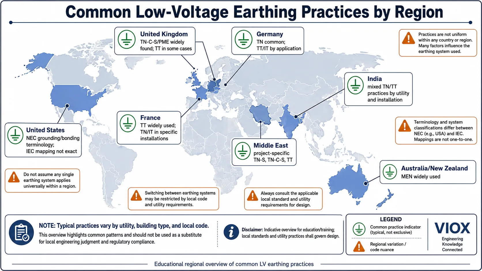
| بریتانیا | TN-C-S/PME widely found, TN-S in older or specific supplies, TT in rural/outbuilding/special cases | Earthing arrangement is usually recorded during inspection. TT often needs RCD-based fault protection because loop impedance is higher. |
| فرانسه | سیستم TT به طور گسترده در بسیاری از شبکههای برق عمومی فشار ضعیف استفاده میشود؛ سیستمهای TN و IT نیز در تأسیسات خاص کاربرد دارند. | در سیستم TT، هماهنگی تجهیزات جریان باقیمانده (RCD) از اهمیت ویژهای برخوردار است. در تأسیسات صنعتی یا مکانهایی که دارای ترانسفورماتور اختصاصی هستند، ممکن است از آرایشهای دیگری استفاده شود. |
| آلمان | سیستمهای TN در بسیاری از تأسیسات رایج هستند؛ سیستمهای TT و IT بر اساس الزامات طراحی یا نوع کاربرد مورد استفاده قرار میگیرند. | استانداردهای DIN VDE و قوانین شرکتهای توزیع برق، آرایش نهایی را تعیین میکنند. سیستم IT در برخی محیطهای پزشکی و صنعتی به کار میرود. |
| هند | بسته به شرکت توزیع، صنعت، منطقه و نوع تأسیسات، میتوان ترکیبی از سیستمهای TN، TT و روشهای ترکیبی را مشاهده کرد. | فرض را بر وجود یک آرایش ملی واحد نگذارید. بررسی در نقطه تحویل انشعاب و رعایت کدهای محلی الزامی است. |
| استرالیا / نیوزیلند | سیستم MEN به طور گسترده استفاده میشود که از نظر مفهومی تا حد زیادی با سیستم TN-C-S قابل مقایسه است. | Neutral-earth bonding rules are central. Local standards such as AS/NZS 3000 govern installation requirements. |
| ایالات متحده | NEC terminology differs from IEC, but grounded neutral with bonding at service equipment is common | The US does not normally describe systems using TN/TT/IT labels in everyday practice. Do not map IEC terms mechanically without engineering review. |
| خاورمیانه | TN-S, TN-C-S, TT, and project-specific arrangements may be used depending on utility and project standards | Large commercial, oil and gas, industrial, and infrastructure projects often specify earthing arrangements explicitly. |
The safest wording is not “this country is always TT” or “this country is always TN-C-S.” Real projects should verify the earthing arrangement at the supply origin, in the electrical design documents, and with the local authority or utility.
How Earthing Systems Affect Fault Current and Protection
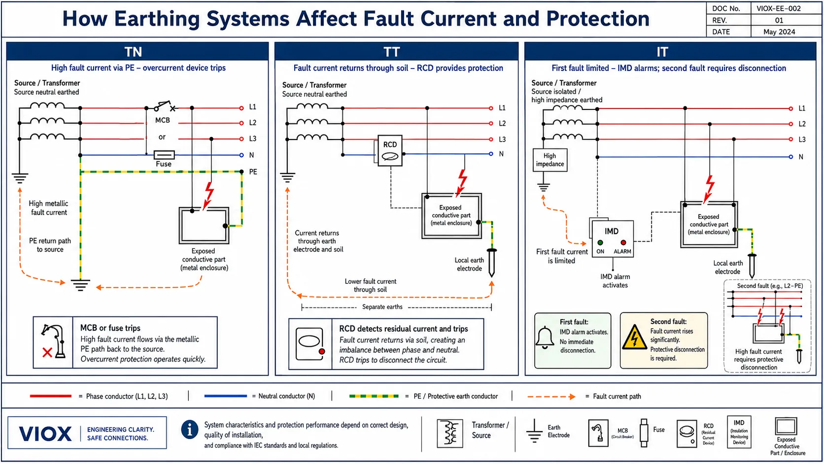
Earthing systems are not only naming conventions. They change how fault current flows and which protective device can disconnect the circuit.
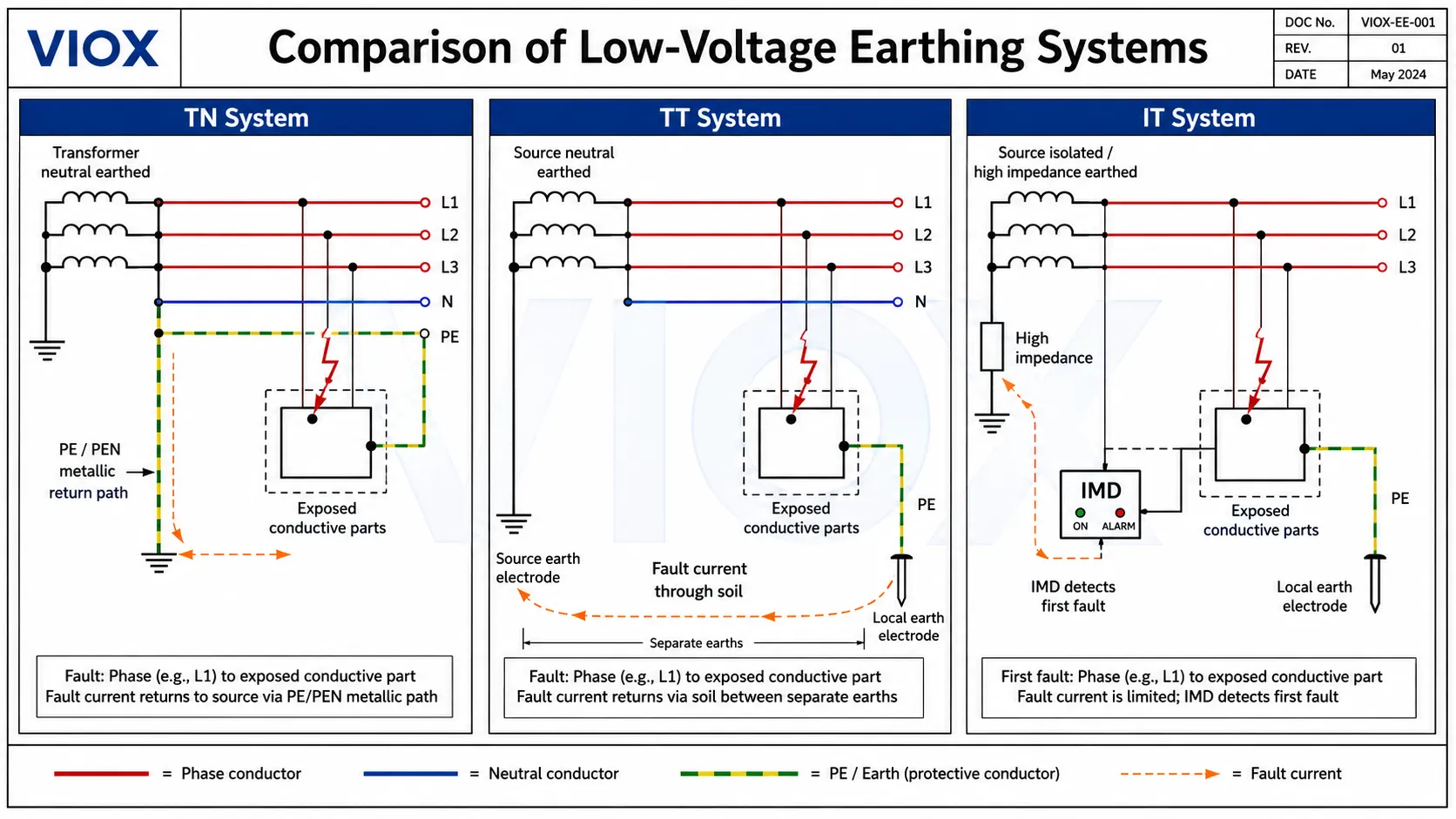
| سیستم | Fault-current path | Typical fault-current level | Protection implication |
|---|---|---|---|
| TN-S | Metallic PE conductor back to source | Usually high | MCBs, fuses, or MCCBs can often clear faults if loop impedance is low enough |
| TN-C | Combined PEN conductor | Usually high, but PEN safety is critical | PEN continuity is essential; RCD use in TN-C section is restricted |
| TN-C-S | PEN supply path then separate PE after split | Usually high | Efficient fault clearing, but broken-PEN risk must be managed |
| TT | Local earth electrode and soil path | Often lower | RCDs are normally required for automatic disconnection |
| فناوری اطلاعات | No solid return path on first fault | Very low on first fault | IMD alarms first fault; second-fault protection must be designed |
TN Systems and Overcurrent Protection
In TN systems, the earth-fault loop is usually metallic. That means a line-to-earth fault can create enough current to operate an MCB, MCCB, or fuse. The design still depends on loop impedance, conductor length, breaker curve, fault level, and disconnection-time requirements.
TT Systems and RCD Protection
In TT systems, the loop impedance is often too high for conventional overcurrent protection to disconnect quickly during an earth fault. RCDs become the main protective device for electric shock protection.
This also affects nuisance tripping. If many circuits with leakage current are placed behind one RCD, the accumulated leakage can approach the trip threshold. VIOX’s article on leakage current vs residual current vs ground current explains this boundary in more detail.
IT Systems and Insulation Monitoring
In IT systems, the first fault should be detected, located, and repaired. The system should not be operated indefinitely with a known first fault. The second fault can create a dangerous condition and must be cleared by protective devices according to the design.
TN vs TT vs IT Comparison Table
| ویژگی | TN System | : نول به زمین تاسیسات متصل نیست، بنابراین نمیتوان آن را "ایمن" فرض کرد. حفاظت کامل 2P توصیه میشود. | : نول از زمین جدا شده است. یک |
|---|---|---|---|
| Source earthing | Source neutral directly earthed | Source neutral directly earthed | Source isolated or impedance-earthed |
| Installation exposed parts | Connected to source earth through PE/PEN | Connected to local earth electrode | Connected to earth, while source is isolated/high impedance |
| Main fault path | Metallic return path | Earth/soil return path | Limited first-fault path |
| Fault current | Usually high | Often low | Low on first fault |
| Main protective logic | Overcurrent devices plus RCDs where required | RCD-based automatic disconnection | Insulation monitoring and second-fault protection |
| Common variants | TN-S, TN-C, TN-C-S | TT | فناوری اطلاعات |
| مزیت اصلی | رفع کارآمد خطا | وابستگی کمتر به مسیر هادی حفاظتی (PE) شبکه سراسری | تداوم سرویسدهی پس از اولین خطا |
| نگرانی اصلی | قطع هادی PEN در سیستمهای TN-C/TN-C-S، بررسی امپدانس حلقه | مقاومت الکترود زمین، هماهنگی کلیدهای محافظ جان (RCD) | اولین خطا باید شناسایی و رفع گردد |
| استفاده معمولی | Residential, commercial, industrial distribution | Rural supplies, overhead networks, installations without utility earth | Hospitals, mines, ships, process plants, critical systems |
سوء تفاهم های رایج
Misunderstanding 1: A Ground Rod Alone Clears Any Fault
A local earth electrode does not automatically create enough current to trip a breaker. In TT systems, fault current through soil may be too low for an MCB or fuse to operate quickly. That is why RCDs are central to TT protection.
Misunderstanding 2: TN-S and TN-C-S Are the Same
They are not the same. TN-S keeps neutral and protective earth separate throughout. TN-C-S uses a combined PEN conductor in part of the supply system, then separates N and PE downstream. That PEN portion creates a different risk profile.
Misunderstanding 3: IT Means Equipment Is Not Earthed
IT does not mean exposed metal parts are left floating. The source is isolated or impedance-earthed, but exposed conductive parts are still connected to protective earth. The system also requires insulation monitoring.
Misunderstanding 4: TT Is Always Safer Than TN
TT avoids some PEN-related risks, but it depends heavily on RCD operation, electrode quality, and correct coordination. Poorly maintained TT systems can be dangerous.
Misunderstanding 5: RCDs Replace Earthing
RCDs detect imbalance and disconnect supply. They do not replace protective bonding, correct earthing, fault-loop design, or conductor sizing.
Misunderstanding 6: One Country Uses Only One Earthing System
Most countries contain mixed practices. Utilities, rural networks, industrial installations, hospitals, older buildings, and new developments may use different arrangements.
سوالات متداول
What is the difference between TN, TT, and IT earthing systems?
TN systems connect exposed conductive parts back to the earthed supply source through protective conductors. TT systems use a local earth electrode at the installation. IT systems isolate the supply from earth or connect it through high impedance, limiting first-fault current.
What does TN-S mean?
TN-S means the supply source is earthed, the installation protective conductors are connected back to that source earth, and the neutral and protective earth conductors remain separate throughout the system.
What does TN-C-S mean?
TN-C-S means the neutral and protective earth functions are combined in a PEN conductor for part of the supply system, then separated into N and PE conductors at the installation origin or service equipment.
Why is TT usually protected by RCDs?
TT earth-fault current returns through the local earth electrode and soil path. That impedance is often too high to operate an MCB or fuse quickly, so RCDs are used to detect residual current and disconnect the circuit.
Why are IT systems used in hospitals and critical facilities?
IT systems allow the first earth fault to be detected without immediate disconnection. This is valuable where continuity of supply matters, such as medical locations or critical industrial processes. The first fault must still be located and repaired.
Is TN-C-S the same as PME or MEN?
PME and MEN are regional terms that are broadly related to TN-C-S concepts, where a combined neutral-earth conductor is earthed at multiple points and separated at the installation. The exact rules depend on national standards and utility practice.
Can an MCB protect a TT system without an RCD?
In many TT installations, an MCB or fuse alone may not disconnect quickly enough for earth faults because the fault current is limited by electrode and soil resistance. RCD protection is usually required for automatic disconnection.
Which earthing system is best?
There is no universal best system. TN, TT, and IT solve different problems. TN is efficient for fault clearing, TT is useful when the utility earth path is not provided or suitable, and IT is selected when first-fault continuity is important.
How do I identify the earthing system in a real installation?
Check the service equipment, neutral-earth bonding arrangement, PE conductor path, local earth electrode, inspection certificate, distribution network operator information, and local wiring documents. Do not identify the system by wire color alone.
Does the United States use TN, TT, or IT?
US installations are normally described using NEC grounding and bonding terminology rather than IEC TN/TT/IT labels. Some arrangements can be compared conceptually, but the mapping is not exact. Use NEC terminology for US code work.
