در این صفحه
برای تاسیساتی که تحت حاکمیت کد ملی برق (NEC) هستند، یک اتصال ارت یا همبندی صرفاً به این دلیل که دو قطعه فلزی با هم تماس دارند یا یک هادی محکم به نظر میرسد، قابل قبول نیست. استاندارد NEC 250.8 هشت دسته از روشهای اتصال را به رسمیت میشناسد، اما کانکتور، ترمینال، بست، ابزار، هادی، محفظه و دستورالعملهای نصب واقعی نیز باید برای کاربرد خاص مناسب باشند.
بنابراین تصمیم صحیح دارای سه دروازه است:
- دروازه روش: آیا روش اتصال توسط ویرایش پذیرفتهشده NEC مجاز است؟
- دروازه محصول: آیا کانکتور، شینه، بست، سیستم جوشکاری یا مجموعه برای این عملکرد دقیق ارتینگ یا همبندی شناسایی شده است؟
- دروازه نصب: آیا هادی، آمادهسازی، ابزار، سختافزار، محیط و اتصال تکمیلشده با دستورالعملهای محصول و تجهیزات مطابقت دارند؟
عبور از تنها یک یا دو دروازه کافی نیست. یک کابلشو لیستشده که با یک هادی پشتیبانینشده استفاده شود، یک پیچ قابلقبول که با درگیری ناکافی نصب شود، یا یک کانکتور صحیح که با ابزار اشتباه اعمال شود، همچنان میتواند منجر به یک اتصال غیرقابلقبول گردد.
یادداشت دامنه: NFPA ویرایش ۲۰۲۶ NEC را به عنوان نسخه منتشرشده فعلی معرفی میکند, ، اما حوزههای قضایی NEC را طبق زمانبندیهای متفاوتی تصویب و اصلاح میکنند. ویرایش قانونی تصویبشده برای پروژه، اصلاحیههای محلی، دستورالعملهای تجهیزات و مرجع ذیصلاح (AHJ) را بررسی کنید. این مقاله یک چارچوب تایید است، نه یک دستورالعمل نصب.
محدوده پوشش NEC 250.8
بخش 250.8 به روشهای اتصال مورد استفاده برای هادیهای ارت تجهیزات، هادیهای الکترود زمین، هادیها یا جامپرهای همبندی و پایانههای مربوط به ارتینگ و همبندی میپردازد. این بخش پاسخ میدهد که چگونه تداوم الکتریکی مورد نیاز میتواند به صورت فیزیکی برقرار شود; ؛ این بخش به طور مستقل تعیین نمیکند که:
- اتصال نول به زمین در کجا باید باشد؛;
- سایز هادی مورد نیاز چقدر است؛;
- آیا به الکترود نیاز است یا خیر؛;
- جریان خطای موجود یا زمان قطع؛;
- اینکه آیا یک ترمینال خاص، هادیهای مسی، آلومینیومی، مفتولی، افشان، فوقافشان یا چندرشتهای را میپذیرد؛;
- گشتاور مورد نیاز، طول لختکردن، قالب یا ترتیب پرس.
این تصمیمات از سایر قوانین NEC، فهرستبندی و برچسبگذاری تجهیزات و مستندات دقیق سازنده حاصل میشوند. برای پرسش جداگانه مرز سیستم، به چگونه یک تابلوی الکتریکی را ارت کنیم.
قوانین الکتریکی OSHA دلیل عملکردی این مراقبت را ارائه میدهند: مسیر ارتینگ از مدارها، تجهیزات و محفظهها باید دائمی، پیوسته و مؤثر باقی بماند، در حالی که مسیرهای فلزی همبندیشده باید تداوم الکتریکی را حفظ کرده و جریان خطای احتمالی را بهطور ایمن عبور دهند.
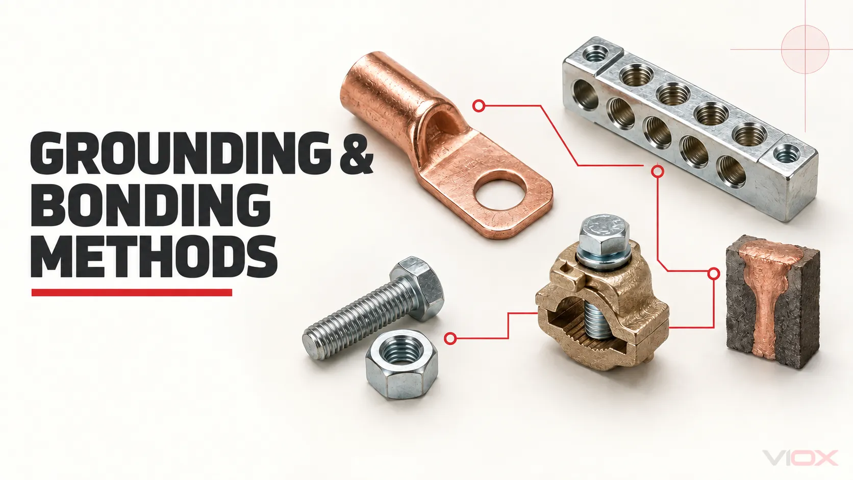
هشت خانواده روشهای اتصال در NEC 250.8
ماتریس زیر، خانوادههای روشهای ثبتشده در مستندات عمومی توسعه NEC سال 2026 سازمان NFPA. این یک ابزار طبقهبندی است، نه جایگزینی برای متن آییننامه مصوب.
| خانواده روش | شکل فیزیکی معمول | چه مواردی باید بررسی شوند | خطای دستهبندی رایج |
|---|---|---|---|
| کانکتور فشاری فهرستشده | کابلشو مکانیکی، کانکتور پرسی، اسپلایس، یا سایر اتصالات از نوع فشاری | دامنه فهرستبندی، جنس هادی، سایز، کلاس، تعداد، درجه حرارتی، آمادهسازی، ابزار و گشتاور | فرض اینکه هر کابلشویی که از نظر فیزیکی جا میگیرد، قابل قبول است |
| شینه ترمینال | شینه ارت یا همبندی با موقعیتهای ترمینال متعدد | سازگاری شینه و تجهیزات، محدوده و تعداد هادی مجاز در هر ترمینال، روش نصب و همبندی محفظه | اتصال دو هادی در یک ترمینالی که برای هادیهای متعدد شناسایی نشده است |
| کانکتور فشاری ارزیابیشده برای ارتینگ و همبندی | کلمپ، بوشینگ، هاب، مهره قفلی، گیره یا کانکتوری که بهطور خاص برای این عملکرد ارزیابی شده است | شناسایی ارتینگ/همبندی، نوع بستر یا الکترود، محدوده هادی، جفت مواد و محیط | جایگزینی یک کانکتور عمومی بدون داشتن مدرک برای استفاده در ارتینگ/همبندی |
| سیستم اتصال جوش احتراقی | واکنش قالبی که یک اتصال متالورژیکی بین هادیهای مشخص یا قطعات فلزی ایجاد میکند | سیستم تأییدشده، ترکیب هادی و بستر، قالب و شارژ، وضعیت سطح، محیط و فرآیند نصب | در نظر گرفتن هر اتصال جوشمانند به عنوان معادل یا مقاوم در برابر خوردگی به صورت جهانی |
| روش بستن با پیچ ماشینی | پیچ ماشینی که با فلز گیرنده درگیر شده یا با یک مهره محکم میشود | درگیری رزوه مورد نیاز، هدف بست، آرایش ترمینال/سختافزار، جنس و دستورالعملهای تجهیزات | استفاده از پیچ ورقکاری، پیچ کناف یا پیچ چوب به دلیل اینکه سفت به نظر میرسد |
| پیچ ماشینی رزوه-ساز | پیچ ماشینی طراحیشده برای ایجاد رزوه در محفظه | نوع بست صحیح، درگیری مورد نیاز، وضعیت سوراخ راهنما، جنس محفظه و دستورالعملها | در نظر گرفتن واژه “خودکار” (self-tapping) به عنوان مدرک کافی |
| اتصال درون یک مجموعه فهرستشده | اتصال پیکربندیشده در کارخانه یا محل که تحت پوشش فهرست مجموعه قرار دارد | مجموعه دقیق، قطعات یا کیتهای تاییدشده، محل تعیینشده و دستورالعملهای نصب | جایگزینی تسمه، شینه، پیچ یا جامپر همبندی با قطعهای که از نظر ظاهری مشابه است |
| یک روش فهرستشده دیگر | یک سیستم اتصال فهرستشده که در موارد بالا به آن اشاره نشده است | فهرستبندی باید مستقیماً هدف و شرایط پیشنهادی را پوشش دهد | تلقی کردن سختافزارهای “دارای ظاهر تأییدشده” یا متداول به عنوان یک روش فهرستشده |
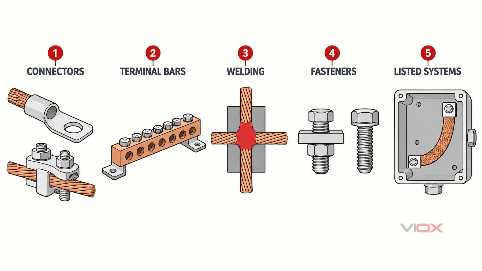
۱. کانکتورهای فشاری لیستشده
کانکتورهای فشاری از طریق بستن مکانیکی یا فشردهسازی هادی، اتصال ایجاد میکنند. بسته به محصول و کاربرد، نمونههای آن شامل کابلشوهای مکانیکی، کانکتورهای فشاری، کانکتورهای اسپلایس بزرگتر و کانکتورهای چندراهی است. UL 486A-486B چندین ساختار مرتبط کانکتور، از جمله کانکتورهای سیمی فشاری و کانکتورهای سیمی جوش داده شده به روش گرمازا را پوشش میدهد؛ دامنه استاندارد محصول آن با دستهبندیهای روش NEC یکسان نیست.
کلمه فهرستشده به این معنی نیست که کانکتور هر هادی که وارد بدنه یا گیره میشود را میپذیرد. بررسی کنید:
- مناسب بودن برای مس، آلومینیوم یا آلومینیوم با روکش مس؛;
- سایز هادی و کلاس رشتهرشته بودن؛;
- تعداد هادیهای مجاز در هر دهانه؛;
- استفاده از نوع مفتولی، رشتهای، فشرده یا با رشتههای ظریف؛;
- آمادهسازی سیم مورد نیاز و طول لختشده؛;
- محدوده دما و ولتاژ کانکتور در صورت کاربرد؛;
- گشتاور بست مورد نیاز یا ابزار پرس و قالب؛;
- شرایط محفظه، مکانهای مرطوب، دفن مستقیم یا محیطهای خورنده.
UL 486A-486B و UL 486C محدودههای مختلف کانکتور را پوشش میدهند. مرجع استاندارد یک محصول به طبقهبندی آن کمک میکند، اما علامتگذاری و دستورالعملهای واقعی تعیینکننده هستند.
۲. ترمینال بارها
یک ترمینال بار، نقاط اتصال متعدد و منظمی را فراهم میکند و در تابلوهای توزیع، تابلوهای برق، محفظهها و تجهیزات کنترلی رایج است. ظاهر آن مشخص نمیکند که آیا این یک شینه نول، شینه ارت تجهیزات، شینه همبندی یا یک قطعه جانبی تأییدشده برای یک محفظه خاص است.
عملکرد مورد نظر شینه، روش نصب یا همبندی، جنس و محدوده هادی، تعداد هادیهای مجاز در هر ترمینال، گشتاور ترمینال و سازگاری با تجهیزات را تأیید کنید. موقعیت پیچی که میتواند بهصورت فیزیکی دو هادی را نگه دارد، لزوماً برای استفاده با دو هادی تأیید نشده است.
تفاوت بین عملکردهای هادی زمینشده و ارت حفاظتی تجهیزات بهطور جداگانه در Neutral Bar vs Grounding Bar.
۳. کانکتورهایی که بهطور خاص برای ارتینگ و همبندی ارزیابی شدهاند
برخی از کانکتورهای فشاری و اتصالات، بهطور خاص بهعنوان تجهیزات ارتینگ و همبندی ارزیابی میشوند. UL Solutions شناسایی میکند الکترودهای میلهای زمین، کلمپها، بوشینگها، مهرههای قفلی، هابها، گیرهها، مش، الکترودهای صفحهای، کوپلینگها، شنتهای کنتور آب، سیم ارت زرهدار و سیستمهای جوش احتراقی را در میان خانواده محصولات ارزیابیشده طبق استاندارد UL 467.
این دستهبندی اهمیت دارد زیرا یک کانکتور سیم حامل جریان و یک کانکتور ارتینگ/همبندی لزوماً دارای کاربرد مورد نظر، شرایط محیطی، ترکیب هادی، رابط الکترود یا ظرفیت جریان خطای یکسانی نیستند. بهجای تکیه بر رنگ یا شکل، به اطلاعات گواهینامه و محدودیتهای نصب قابل اعمال برای مدل دقیق توجه کنید.
۴. سیستمهای اتصال جوش اگزوترمیک
یک فرآیند احتراقی از یک واکنش کنترلشده برای ایجاد یک اتصال متالورژیکی بین هادیها یا قطعات فلزی مشخص استفاده میکند. این روش میتواند در مواردی که به یک اتصال دائمی نیاز است ارزشمند باشد، اما این روش یک راهکار همگانی نیست.
پذیرش به سیستم کامل بستگی دارد: مواد هادی و بستر، اندازهها، قالب، مواد جوشکاری، آمادهسازی سطح، رطوبت و شرایط محیطی، روش نصب و معیارهای بازرسی. ادعا نکنید که هر اتصال گرمازا (exothermic) در برابر خوردگی، نگرانیهای مربوط به نگهداری یا نقصهای اجرایی مصون است.
۵. اتصالات پیچ ماشینی
برای روش پیچ ماشینی که در NEC 250.8 به آن پرداخته شده است، بست باید درگیر شود با حداقل دو رزوه یا با یک مهره محکم شود. این حد آستانه، هر پیچ موجودی را قابل قبول نمیسازد. پیچ، فلز پذیرنده، آرایش ترمینال و نحوه استفاده همچنان باید با تجهیزات و الزامات مربوطه مطابقت داشته باشند.
تأیید کنید که بست یک پیچ ماشینی است، شرایط درگیری رزوه یا مهره رعایت شده است و اتصال به گونهای نیست که از سختافزار مشترک به نحوی که تجهیزات اجازه نمیدهد، استفاده کند. از پیچهای تیز، دندهدرشت مخصوص ورق فلزی، کناف (drywall) یا پیچ چوب استفاده نکنید.
۶. پیچهای ماشینی رزوه-ساز
یک پیچ ماشینی رزوه-ساز، رزوههای ماشینی را در محفظه ایجاد یا شکلدهی میکند و باید درگیری مورد نیاز را حاصل کند. این مورد خاصتر از اصطلاح عامیانه پیچ خودکار (self-tapping screw), است که میتواند چندین نوع بست با اشکال رزوه و کاربردهای متفاوت را توصیف کند.
پذیرش مستلزم شناسایی نوع دقیق اتصالدهنده، جنس و ضخامت محفظه، وضعیت سوراخ راهنما در صورت لزوم، درگیری مورد نیاز و دستورالعملهای تجهیزات است. شباهت ظاهری به یک پیچ ارت تأییدشده، دلیلی بر تأیید آن نیست.
۷. اتصالاتی که بخشی از یک مجموعه فهرستشده هستند
یک اتصال ارت یا همبندی میتواند به عنوان بخشی از یک مجموعه لیستشده پذیرفته شود، مشروط بر اینکه در محدوده آن مجموعه ساخته و نصب شده باشد. مثالها میتوانند شامل تسمه همبندی تعیینشده، کیت شینه ارت، اتصال محفظه، جامپر همبندی درب، یا اتصال کارخانهای باشند؛ اما تنها زمانی که قطعات و چیدمان دقیق تحت پوشش باشند.
شواهد عملی شامل هویت تجهیزات، لوازم جانبی یا کیت تأییدشده، محل نصب تعیینشده، دستورالعملها و سختافزار مورد نیاز است. جایگزینی یک قطعه از مجموعه لیستشده با یک جزء عمومی میتواند اتصال را از پیکربندی ارزیابیشده خارج کند، حتی اگر از نظر ظاهری معادل به نظر برسد.
۸. سایر روشهای فهرستشده
این دسته نهایی، روشی لیستشده را مجاز میداند که به طور دقیق در توصیفهای قبلی نمیگنجد. این به معنای اجازه بداههپردازی نیست. لیستشدن محصول باید مستقیماً از هدف ارتینگ یا همبندی پیشنهادی، هادی یا بستر، محیط و شرایط نصب پشتیبانی کند.
“رویه معمول”، یک عکس آنلاین، توصیف تأمینکننده، یا پذیرش یک نصب متفاوت توسط بازرس، لیستشدن محصول موجود را اثبات نمیکند.
مسیر تایید سهدروازهای
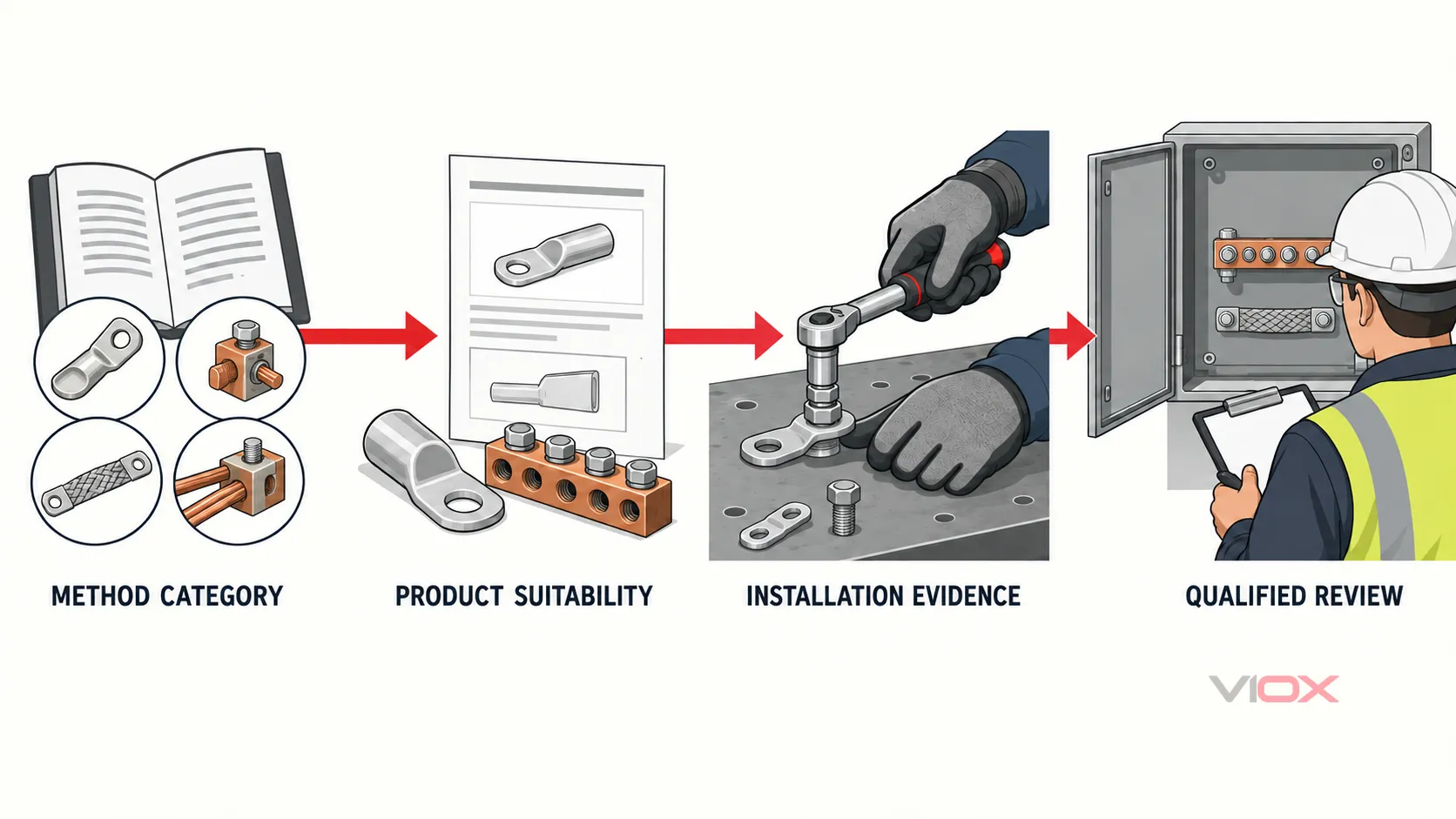
گام ۱: تأیید دسته روش مجاز
شناسایی کنید که کدام خانواده روشهای NEC 250.8، اتصال پیشنهادی را توصیف میکند. سپس ویرایش پذیرفتهشده محلی و هر قانون مرتبط حاکم بر تجهیزات، هادی، الکترود، استخر، سرویس، سیستم مشتقشده جداگانه یا کاربری خاص را بررسی کنید.
گام ۲: تأیید مناسب بودن محصول یا مجموعه
نشانهگذاری محصول، سوابق گواهینامه، شناسه کاتالوگ، برگه اطلاعات و دستورالعملهای تجهیزات را جمعآوری کنید. عملکرد مورد نظر و محیط را تطبیق دهید—نه فقط ابعاد فیزیکی را.
برای یک کانکتور، جنس، اندازه، کلاس هادی، تعداد هادیها و محدوده محیطی را تأیید کنید. برای یک مجموعه لیستشده، لوازم جانبی تأییدشده و محل دقیق نصب را تأیید کنید. برای یک اتصال پرسی، هادی، کانکتور، ابزار، قالب (die) و توالی اجرا را به عنوان یک سیستم واحد در نظر بگیرید. UL 1976, ، برای مثال، ابزارهای پرس را تنها برای رتبهبندیهای دستگاه اتصال و کاربردهای تأییدشده با آن ابزار ارزیابی میکند.
گیت ۳: تأیید شواهد نصب
یک فرد واجد شرایط باید تأیید کند که اتصال تکمیلشده از مستندات پیروی میکند. بسته به روش، شواهد ممکن است شامل موارد زیر باشد:
- مواد صحیح هادی و بستر (substrate)؛;
- تعداد و محدوده مجاز هادی؛;
- طول لختکردن مشخصشده و آمادهسازی سطح؛;
- ابزار، قالب، قالب ریختهگری، شارژ، پیچ، مهره یا کیت لوازم جانبی صحیح؛;
- توالی گشتاور یا پرس (کریمپ) مستندشده؛;
- درگیری کافی رزوه؛;
- تمهیدات مناسب محیطی و ضدخوردگی؛;
- عدم وجود آسیب، آلودگی، رشتههای شل، تغییرات غیرمجاز یا سختافزار جابهجاشده؛;
- برچسبهای مورد نیاز، سوابق مدار و مستندات بازرسی.
مقادیر مورد نیاز باید از تجهیزات و سیستم اتصال دقیق استخراج شوند. این مقاله عمداً هیچ جدول جهانی برای گشتاور، طول لختکردن یا اندازه هادی ارائه نمیدهد.
اتصالاتی که باید بازبینی فوری را فعال کنند
شرایط زیر در هر مورد ثابتکننده نقص نیستند، اما پیش از پذیرش نیاز به مستندسازی دارند:
| مشاهده | چرا نیاز به بازبینی دارد | مدارک مورد نیاز |
|---|---|---|
| اتصالی که تنها به لحیمکاری وابسته است | استاندارد NEC 250.8 اتصال زمین یا همبندی که صرفاً بر لحیمکاری متکی باشد را نمیپذیرد | روش جایگزین تأییدشده یا مستندات برای یک سیستم اتصال که بهطور جداگانه مجاز شمرده شده است |
| استفاده از پیچ ورقفلزی، پیچ کناف یا پیچ چوب | این مورد در دستهبندی پیچهای ماشینی یا پیچهای دندهساز ماشینی که در قانون توصیف شده، قرار نمیگیرد | اتصالدهنده مجاز صحیح و دستورالعملهای تجهیزات |
| دو یا چند هادی از یک ترمینال مشترک استفاده میکنند | ممکن است ترمینال برای آن تعداد هادی یا ترکیب خاص، شناسایی نشده باشد | علامتگذاری ترمینال و مستندات سازنده |
| آلومینیوم و مس در یک کانکتور تأییدنشده به هم میرسند | سازگاری مواد، آمادهسازی، آبکاری و محدودیتهای محیطی ممکن است متفاوت باشد | علامتگذاری دقیق کانکتور و دستورالعملها |
| هادی با رشتههای نازک در یک کابلشو استاندارد وارد میشود | کابلشو ممکن است بدون استفاده از فرول یا آداپتور ارزیابیشده، آن کلاس هادی را نپذیرد | مستندات کانکتور، فرول/آداپتور، ابزار و هادی |
| یک تسمه اتصال همبندی یا کیت شینه ارت جایگزین شده است | مجموعه کامل فهرستشده ممکن است به یک لوازم جانبی و محل نصب خاص نیاز داشته باشد | دستورالعملهای مونتاژ و هویت قطعات تأییدشده |
| مقدار مقاومت به عنوان تنها معیار پذیرش ارائه شده است | قرائت پایین به معنای اثبات فهرستشدن، یکپارچگی مکانیکی، سازگاری هادی یا مناسب بودن برای جریان خطا نیست | روش، محصول، نصب و شواهد روش تست |
چرا یک عدد مقاومت، قانون جهانی قبولی/رد نیست
اندازهگیریهای پیوستگی یا مقاومت پایین میتوانند در زمان راهاندازی یا نگهداری، در صورتی که استاندارد مربوطه، روش تست، ابزار، محل اتصال، مبنا و معیار پذیرش تعریف شده باشند، کمککننده باشند. این اندازهگیریها جایگزین سه دروازه اصلی نمیشوند.
آزمونهای مختلف به پرسشهای متفاوتی پاسخ میدهند: پیوستگی همبندی نقطه به نقطه، مقاومت الکترود زمین نسبت به زمین، پیوستگی هادی حفاظتی و امپدانس مسیر جریان خطا، اندازهگیریهای قابل جایگزینی با یکدیگر نیستند. مقداری که در یک مشخصات آزمون پذیرش استفاده میشود، نباید در هر بررسی اتصال زمین یا همبندی کپی شود.
الزام OSHA برای یک مسیر دائمی، پیوسته و مؤثر، یک الزام عملکردی است، نه یک آستانه مقاومت جهانی برای هر اتصالدهنده. پیش از تعیین معیار قبولی عددی، از مشخصات پروژه، الزامات مصوب و روش آزمون تعریفشده استفاده کنید.
چکلیست بازبینی توسط فرد واجد شرایط
از این چکلیست برای سازماندهی مستندات پیش از تأیید یا تدارکات استفاده کنید:
- ویرایش مصوب NEC، اصلاحیههای محلی و قاعده حاکم بر تجهیزات را ثبت کنید.
- عملکرد الکتریکی را شناسایی کنید: زمین کردن تجهیزات، اتصال الکترود زمین، همبندی یا سایر عملکردهای تعریفشده.
- اتصال پیشنهادی را به یکی از خانوادههای روشهای مجاز در NEC 250.8 اختصاص دهید.
- سازنده، شماره کاتالوگ، رده گواهینامه و استاندارد کاربردی محصول یا مجموعه دقیق را ثبت کنید.
- جنس هادی، اندازه، کلاس، تعداد و الزامات آمادهسازی را مطابقت دهید.
- ابزار، قالب، مدل، مواد جوشکاری، بست، مهره، ترمینال یا کیت لوازم جانبی متناسب را انتخاب کنید.
- گشتاور مشخصشده، ترتیب پرس، طول لختکردن سیم، درگیری رزوه و محدودیتهای محیطی را از دستورالعملهای مربوطه ثبت کنید.
- اتصال تکمیلشده را از نظر سختافزار صحیح، وضعیت، شناسایی و جایگزینیهای غیرمجاز بازرسی کنید.
- فقط از روش تست و معیار پذیرش مورد نیاز پروژه، تجهیزات، برنامه نگهداری یا مرجع ذیصلاح استفاده کنید.
- مستندات مورد نیاز برای بازرسی، نگهداری و تعویض را حفظ کنید.
برای محدوده وسیعتر تجهیزات سرویس و تابلوی پاییندست، ادامه دهید با راهنمای ارتینگ تابلوی VIOX مطابق با ماده 250 NEC. هنگام ارزیابی یک کابلشو یا اتصال پرسی، به یاد داشته باشید که محدوده کابلشوهای VIOX یک نقطه شروع برای محصول است—نه گواهی بر اینکه هر مدل برای یک کاربرد خاص ارتینگ یا همبندی NEC فهرست شده یا مناسب است. پیش از مشخصات فنی، مستندات دقیق مدل را تأیید کنید.
منابع
- NFPA 70 — کد ملی برق، ویرایش فعلی و وضعیت سند
- سوابق توسعه عمومی NEC 2026 سازمان NFPA — بخش 250.8 روشهای مجاز
- استانداردها و تعاملات UL — اتصالات سیم UL 486A-486B
- استانداردها و تعاملات UL — اتصالات سیم اسپلایس (اتصالدهنده) UL 486C
- راهکارهای UL — ارزیابی تجهیزات ارتینگ و همبندی
- استانداردها و تعاملات UL — ابزارهای پرس UL 1976 برای استفاده با تجهیزات اتصال
- OSHA — 29 CFR 1910.304، طراحی و حفاظت سیمکشی
- OSHA — 29 CFR 1910.305، روشهای سیمکشی، قطعات و تجهیزات