
Why EV Chargers Aren’t Like Other Appliances
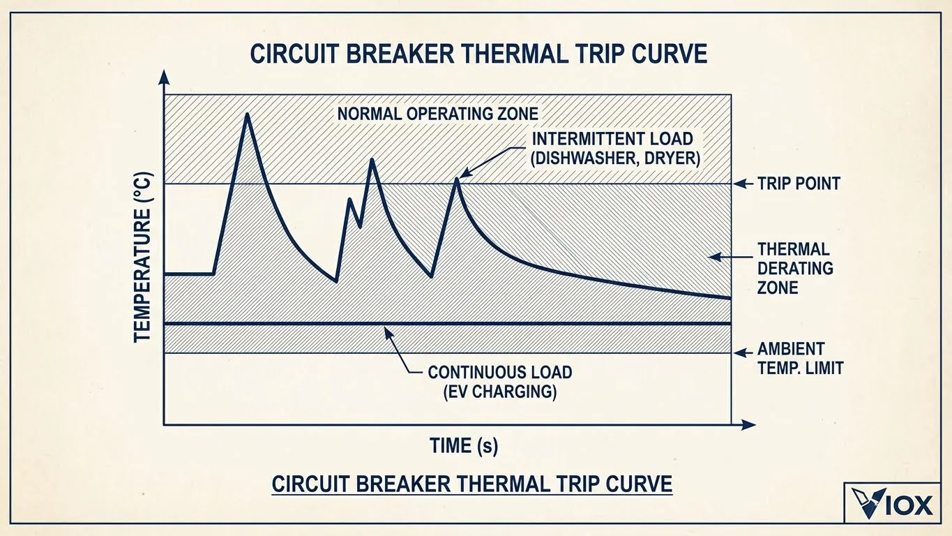
When installers transition from traditional residential work to EV charging infrastructure, one critical difference becomes immediately apparent: circuit breakers must be sized differently for continuous loads. Unlike a dishwasher that cycles on and off or a dryer that runs for an hour, electric vehicle chargers operate at sustained high current for 3-8 hours continuously—placing them in a unique category that demands specialized protection sizing.
According to both the NEC (National Electrical Code) Article 625 and IEC 60364-7-722 standards, any load expected to run for three hours or more qualifies as a “continuous load.” This classification triggers mandatory derating requirements that many installers initially overlook. The fundamental rule is straightforward but non-negotiable:
Minimum Breaker Rating = Charger Current × 1.25
This 125% factor accounts for thermal accumulation in breaker contacts, bus bars, and terminations. When current flows continuously, heat builds up in electrical connections faster than it can dissipate. Standard breakers rated at 80% of their nominal capacity for continuous duty require this safety margin to prevent nuisance tripping and premature component degradation.
Consider the thermal profile difference: a 30A electric dryer might draw full current for 45 minutes, then idle, allowing the breaker contacts to cool. A 32A EV charger maintains that 32A draw for five consecutive hours during overnight charging. This sustained thermal stress is why matching breaker amperage to charger amperage is the most common—and dangerous—sizing error.
Let’s examine the practical application with concrete examples:
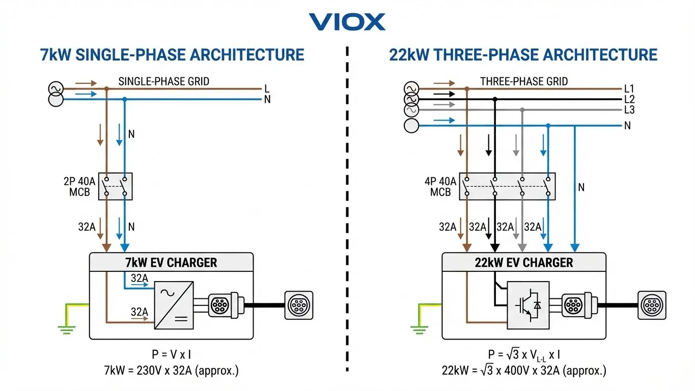
7kW Single-Phase Calculation:
- Power: 7,000W
- Voltage: 230V (IEC) or 240V (NEC)
- Charger current: 7,000W ÷ 230V = 30.4A
- Continuous load factor: 30.4A × 1.25 = 38A
- Next standard breaker size: 40A ✓
22kW Three-Phase Calculation:
- Power: 22,000W
- Voltage: 400V three-phase (IEC)
- Current per phase: 22,000W ÷ (√3 × 400V) = 31.7A
- Continuous load factor: 31.7A × 1.25 = 39.6A
- Next standard breaker size: 40A per pole ✓
Notice that despite the threefold power difference between 7kW and 22kW chargers, both require 40A breakers—the key distinction lies in the number of poles (2P vs 3P/4P) rather than the amperage rating itself. This counterintuitive result stems from three-phase power’s ability to distribute current across multiple conductors.
7kW EV Chargers: The Residential Standard
Technical Specifications
The 7kW charging tier represents the global sweet spot for home installations, offering overnight full-charge capability for most passenger EVs while working within standard residential electrical infrastructure. The technical parameters are:
- Voltage: 230V single-phase (IEC markets) / 240V (NEC markets)
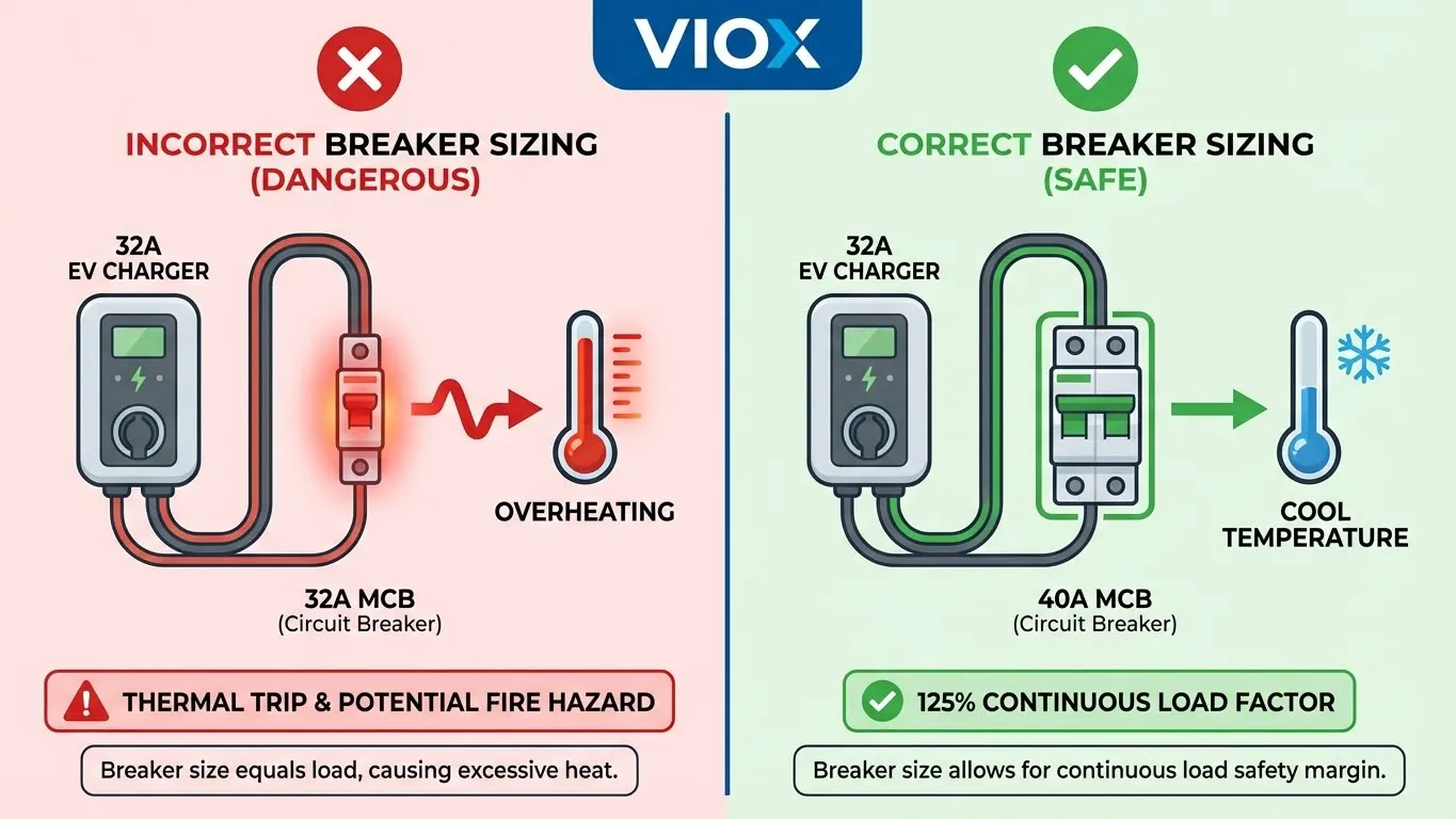
- Charger current draw: 30.4A (at 230V) or 29.2A (at 240V)
- Applied 125% factor: 38A minimum circuit capacity
- Recommended breaker: 40A (NOT 32A)
- Typical charging rate: 25-30 miles of range per hour
Why 40A, Not 32A?
The persistent myth that a “32A charger needs a 32A breaker” stems from confusing the charger’s operating current with the circuit protection requirement. Here’s what actually happens inside the breaker during continuous EV charging:
Thermal Accumulation Cascade:
- Current flows through the breaker’s bimetallic strip or electronic sensor
- Resistive heating occurs at contact points and terminals
- Heat dissipates into surrounding air and enclosure
- At 80% duty (continuous load), heat generation equals dissipation—equilibrium
- At 100% duty, heat accumulates faster than it dissipates—thermal runaway risk
VIOX miniature circuit breakers incorporate silver-alloy contact technology that reduces contact resistance by 15-20% compared to standard brass contacts. This translates to lower operating temperatures and extended service life in continuous-duty applications like EV charging. However, even with superior materials, the 125% sizing rule remains mandatory for code compliance and warranty validity.
When installers select a 32A breaker for a 32A charger, they’re operating the breaker at 100% of its rated capacity continuously. Most breakers will trip within 60-90 minutes under these conditions—not due to overcurrent, but due to thermal overload protection activating. Field reports consistently show 32A breakers in 7kW installations failing within 18-24 months from thermal fatigue.
Pole Configuration Options
Selecting between 1P+N and 2P configurations depends on system grounding and local code requirements:
1P+N MCB (with neutral protection):
- Suitable for TN-S and TN-C-S earthing systems
- Protects both line and neutral conductors
- Required in UK (BS 7671) and many IEC markets
- Ensures isolation of both current-carrying conductors during maintenance
2P MCB (line-to-line protection):
- Standard in NEC installations with separate ground conductor
- Protects L1 and L2 in 240V split-phase systems
- Lower cost than 1P+N due to simplified neutral switching
- Common in North American residential panels
For guidance on selecting the appropriate MCB type for your application, see our complete guide to choosing miniature circuit breakers. Remember that EV chargers require both overcurrent protection (MCB) and earth leakage protection (RCD)—understanding the difference between RCD and MCB is crucial for compliant installations.
Wire Sizing Companion
Circuit breaker sizing is only half the equation—conductor sizing must match the breaker’s rating while accounting for voltage drop:
Standard 7kW Installation (≤20m run):
- Copper: 6mm² (10 AWG equivalent)
- Ampacity: 41A (clipped direct method C)
- Voltage drop: <1.5% at 30.4A over 20m
- Cost: Moderate
Future-Proof 7kW Installation (11kW upgrade path):
- Copper: 10mm² (8 AWG equivalent)
- Ampacity: 57A (clipped direct method C)
- Accommodates future 48A (11kW) charger without rewiring
- Voltage drop: <1% at 30.4A over 30m
- Cost: +30% material, but eliminates future rewiring labor
Long-Run Installations (>20m):
- Voltage drop becomes dominant factor
- Use 10mm² copper minimum
- Consider 16mm² for runs exceeding 40m
- Alternatively, relocate distribution panel closer to charge point
If your installation requires evaluating existing panel capacity, consult our guide on upgrading 100A panels for EV chargers, which includes load calculation worksheets and panel sizing decision trees.
22kW EV Chargers: Commercial & High-Performance Applications
Technical Specifications
The 22kW tier serves commercial fleets, workplace charging stations, and high-end residential installations where rapid turnaround matters. Unlike 7kW chargers that work within single-phase infrastructure, 22kW installations demand three-phase power—a critical infrastructure requirement that limits deployment primarily to commercial and industrial settings.
- Voltage: 400V three-phase (IEC markets) / 208V three-phase (NEC commercial)
- Current per phase: 31.7A at 400V or 61A at 208V
- Applied 125% factor: 39.6A minimum (400V system)
- Recommended breaker: 40A 3P or 4P
- Typical charging rate: 75-90 miles of range per hour
The stark current difference between 400V and 208V systems illustrates why low-voltage three-phase installations (common in older North American commercial buildings) struggle with EV charging infrastructure. A 208V system requires nearly twice the current for the same power output, necessitating heavier conductors and larger breakers—often making retrofits economically prohibitive.
The Three-Phase Advantage
Three-phase power distribution offers fundamental advantages for high-power EV charging:
Current Distribution:
- Single-phase 22kW equivalent: Would require ~95A at 230V (impractical)
- Three-phase 22kW: Only 31.7A per phase at 400V
- Each conductor carries one-third of the load
- Neutral current approaches zero in balanced systems
Infrastructure Efficiency:
- Lower per-conductor current means smaller wire gauge requirements
- Reduced I²R losses across the distribution system
- Better utilization of transformer capacity
- Enables multiple 22kW chargers from single three-phase panel
Practical Constraints:
- Standard residential service: Single-phase only (most markets)
- Small commercial: May have three-phase service entrance, single-phase distribution
- Industrial/large commercial: Full three-phase distribution to sub-panels
- High-end residential: Three-phase available in some European markets, rare in North America
For installers accustomed to single-phase work, the conceptual shift is significant: you’re no longer thinking about “hot and neutral” but rather L1, L2, L3, and neutral, with current flowing between phases rather than phase-to-neutral.
Why 22kW Isn’t Always 63A
A persistent sizing error stems from misapplying the “32A charger = 40A breaker” residential logic to three-phase installations. The confusion typically follows this faulty reasoning:
❌ Incorrect Logic:
“A 7kW single-phase charger draws 30A and needs 40A breaker, so a 22kW charger (3× the power) needs 3× the breaker: 120A or at least 100A.”
✓ Correct Analysis:
- 22,000W ÷ (√3 × 400V) = 31.7A per phase
- 31.7A × 1.25 = 39.6A
- Next standard size: 40A breaker
The mathematics are unambiguous: 22kW three-phase installations require 40A breakers, not 63A. The 63A size appears in specifications under specific conditions:
When 63A Is Appropriate:
- Cable runs exceeding 50 meters with significant voltage drop
- Ambient temperatures consistently above 40°C (104°F)
- Future expansion to 44kW (dual-charger) capability
- Integration with building load management systems requiring headroom
- Compliance with regional codes requiring 150% or 160% factors (some German standards)
When 63A Is Wasteful:
- Standard 22kW installation, cable run <30m, moderate climate
- Creates selectivity problems with upstream 80A or 100A main breakers
- Increases arc flash hazard classification
- Higher material cost with no safety benefit
For installations requiring the robustness and adjustability of molded case circuit breakers, refer to our MCCB technical guide. As discussed in our residential vs industrial breaker comparison, the choice between MCB and MCCB involves analyzing duty cycle, environmental conditions, and integration requirements rather than simple power thresholds.
MCB vs MCCB Decision Point
For standard 22kW installations, MCB is sufficient and cost-effective. The decision to upgrade to MCCB should be driven by specific technical requirements:
Upgrade to MCCB When:
- Multiple Chargers on Shared Infrastructure
- Deploying 3+ chargers from single distribution panel
- Need for adjustable trip settings to coordinate with load management
- Benefit from electronic trip units with communication protocols
- Harsh Environmental Conditions
- Outdoor installations in extreme climates (-40°C to +70°C)
- Coastal environments with salt spray exposure
- Industrial settings with vibration, dust, or chemical exposure
- MCCB enclosures offer superior IP ratings (IP65/IP67 vs MCB’s typical IP20)
- Building Management System Integration
- Facilities with existing SCADA or BAS infrastructure
- Modbus RTU/TCP communication for energy monitoring
- Remote trip capability for demand response programs
- Arc flash reduction through zone-selective interlocking
Stick with MCB When:
- Single or dual charger installation
- Controlled indoor environment
- Standard residential or light commercial application
- Cost optimization is priority
- Maintenance staff lacks MCCB adjustment training
VIOX MCBs incorporate the same thermomagnetic operating principles as our MCCB line, with trip curves tested to IEC 60898-1 standards for consistent performance. The rated breaking capacity (10kA for residential MCBs, up to 25kA for industrial MCBs) exceeds typical EV charging installation requirements.
Beyond Overcurrent: Why RCDs Are Non-Negotiable
Miniature circuit breakers and molded case circuit breakers protect against overcurrent (overload and short circuit) conditions. They monitor current magnitude and interrupt the circuit when thresholds are exceeded. However, they provide zero protection against the most dangerous fault scenario in EV charging: earth leakage currents that can cause electrocution without ever tripping an MCB.
What MCBs Don’t Detect:
- Leakage current through damaged insulation to ground
- Fault currents below the magnetic trip threshold (typically 5-10× rated current)
- DC fault currents (common in EV charging systems)
- Ground faults in the vehicle chassis or charging cable
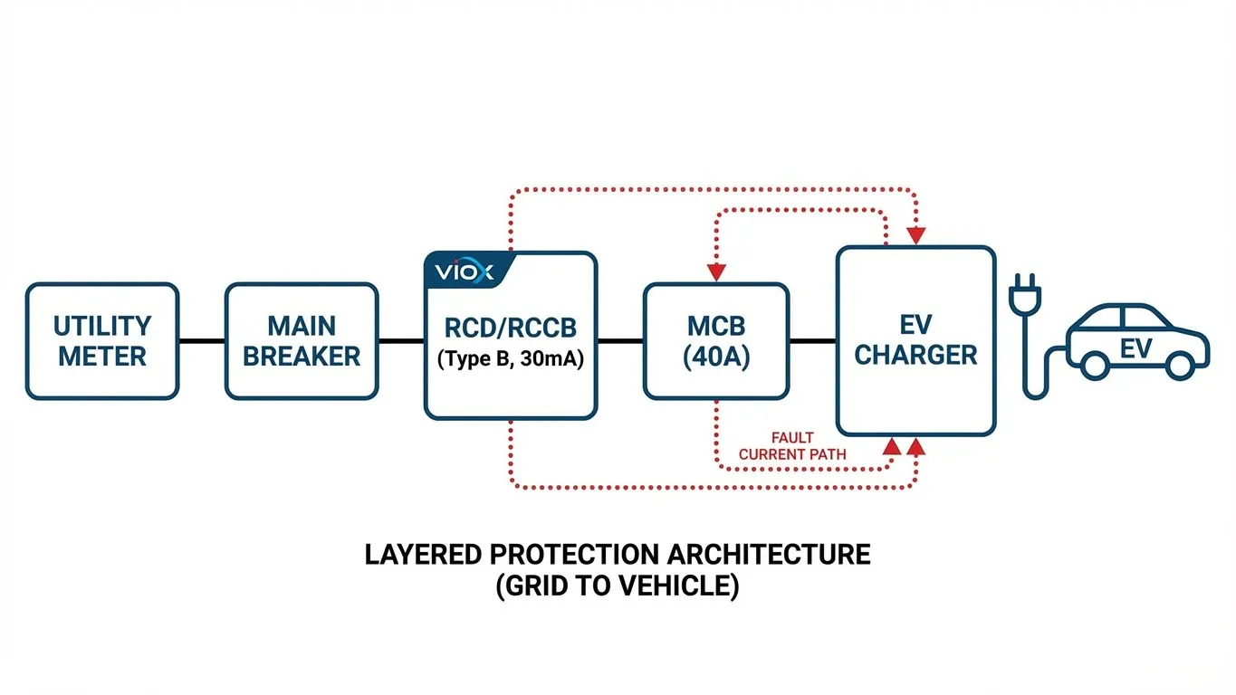
This is where Residual Current Devices (RCDs) become mandatory. RCDs continuously monitor the current balance between line and neutral conductors. Any imbalance exceeding 30mA (IΔn = 30mA for personnel protection) indicates current leaking to ground—potentially through a person—and triggers instantaneous disconnection within 30ms.
EV-Specific RCD Requirements:
Electric vehicles introduce DC fault current complications that standard Type A RCDs cannot detect. Modern EVs use rectifiers in their onboard chargers, and DC faults can saturate the magnetic core of Type A RCDs, rendering them ineffective.
Type A RCD: Detects AC fault currents only
- Suitable for traditional appliances
- ⚠️ Not adequate for EV charging
- May fail to trip under DC fault conditions
Type B RCD: Detects AC and DC fault currents
- Required for EV charging per IEC 61851-1
- Detects smooth DC (6mA threshold) and pulsating DC
- Significantly higher cost than Type A (3-5× price premium)
- ✓ Recommended for all EV installations
Type F RCD: Enhanced Type A with 1kHz frequency response
- Suitable for VFDs and inverter-driven equipment
- ⚠️ Insufficient for EV charging (no DC detection)
For a detailed comparison of RCD types specifically for EV applications, including cost-benefit analysis and alternative solutions like RDC-DD monitoring, see our comprehensive RCCB Type B vs Type F vs Type EV guide.
Combined Protection Solutions
RCBOs (Residual Current Circuit Breaker with Overcurrent Protection) integrate RCD and MCB functionality in a single DIN rail module, offering several advantages for EV charging installations:
Pros:
- Space efficiency: Occupies 2-4 DIN rail modules vs 4-6 for separate RCD+MCB
- Simplified wiring: Single device, fewer interconnections
- Selective protection: Fault on EV circuit doesn’t trip other loads
- Reduced panel congestion: Critical for retrofits in tight enclosures
Cons:
- Higher unit cost: 2-3× the combined cost of separate RCD and MCB
- All-or-nothing tripping: Earth fault and overcurrent both disconnect the same circuit
- Limited availability: Type B RCBOs are specialty items with longer lead times
- Maintenance complexity: Single device failure disables both protections
For multi-charger installations (workplace charging, fleet depots), shared RCD topology often proves more economical: one Type B RCD protects multiple MCB-protected charger circuits. This approach concentrates the expensive DC fault detection in a single upstream device while maintaining selective overcurrent protection. See our RCBO vs AFDD guide for alternative protection architectures.
Installation Best Practices from the Field
Panel Capacity Assessment
Before specifying breaker sizes, verify that the existing electrical service can support the additional load. Most residential services fall into two categories:
100A Service (Common in Pre-2000 Construction):
- Total available power: 100A × 240V = 24kW
- Continuous safe load (80% rule): 19.2kW
- Typical existing load: 12-15kW (HVAC, appliances, lighting)
- Remaining capacity: ~4-7kW
- Verdict: Marginal for 7kW charger, panel upgrade recommended
200A Service (Standard Modern Residential):
- Total available power: 200A × 240V = 48kW
- Continuous safe load: 38.4kW
- Typical existing load: 15-20kW
- Remaining capacity: ~18-23kW
- Verdict: Adequate for 7kW charger, possibly 11kW with load management
Load Calculation Method (NEC Article 220 / IEC 60364-3):
- Calculate general lighting and receptacle load (3 VA/ft² or 33 VA/m²)
- Add appliance loads at nameplate ratings
- Apply demand factors per code tables
- Add EV charger at 125% of continuous rating (7kW charger = 8.75kW minimum)
- Compare total calculated load to service rating
If calculated load exceeds 80% of service capacity, options include:
- Service upgrade (200A or 400A)
- Load management system (sequential charging)
- Reducing charger power (22kW → 11kW → 7kW)
For residential panel upgrade considerations specific to EV charging, our 100A panel EV charger upgrade guide provides decision trees and cost-benefit analysis.
Ambient Temperature Derating
Standard breaker ratings assume an ambient temperature of 30°C (86°F). Installations exceeding this baseline require derating to prevent thermal tripping:
IEC 60898-1 Derating Factors:
- 30°C (86°F): 1.0 (no derating)
- 40°C (104°F): 0.91 (multiply breaker rating by 0.91)
- 50°C (122°F): 0.82
- 60°C (140°F): 0.71
Real-World Scenarios:
Outdoor Charger in Arizona Summer:
- Ambient: 45°C (113°F)
- Derating factor: ~0.86
- 40A breaker effective rating: 40A × 0.86 = 34.4A
- 7kW charger draw: 30.4A
- Safety margin: Adequate but minimal—consider 50A breaker
Enclosed Panel, Direct Sunlight:
- Panel interior can reach 55°C (131°F)
- Derating factor: ~0.76
- 40A breaker effective rating: 40A × 0.76 = 30.4A
- 7kW charger draw: 30.4A
- Safety margin: Zero—upgrade to 50A mandatory
Climate-Controlled Indoor Installation:
- Consistent 22°C (72°F)
- Derating factor: 1.05 (slight uprating)
- Standard sizing applies
VIOX circuit breakers utilize silver-tungsten alloy contacts with superior thermal conductivity (410 W/m·K vs 385 W/m·K for pure copper). This reduces contact temperature rise by 8-12°C under continuous load, effectively providing built-in thermal margin. However, code-required derating factors must still be applied for compliance.
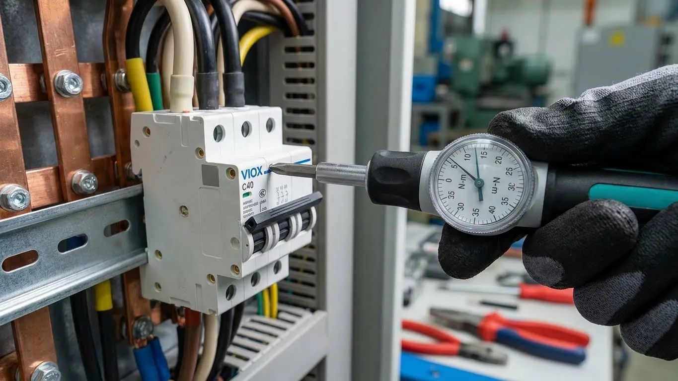
Terminal Torque: The Hidden Failure Point
Field failure analysis reveals that improper terminal torque accounts for 30-40% of premature breaker failures in EV charging installations—more than any other single factor. The consequences cascade:
Under-Torquing (Most Common Error):
- High contact resistance at terminal interface
- Localized heating (I²R losses)
- Oxidation of copper surfaces
- Further resistance increase (positive feedback loop)
- Thermal damage to breaker housing or busbar
- Catastrophic failure or fire risk
Over-Torquing:
- Cracking of terminal block housing (common in polycarbonate housings)
- Thread stripping in brass terminals
- Deformation of conductor causing future loosening
- Immediate failure or latent defect
VIOX Terminal Torque Specifications:
| Breaker Rating | Terminal Torque | Conductor Size |
|---|---|---|
| 16-25A MCB | 2.0 N·m | 2.5-10mm² |
| 32-63A MCB | 2.5 N·m | 6-16mm² |
| 80-125A MCB | 3.5 N·m | 10-35mm² |
Installation Protocol:
- Strip conductor to exact length shown on breaker label (typically 12mm)
- Insert conductor fully into terminal until conductor stop
- Apply torque gradually using calibrated screwdriver
- Verify torque with torque-limiting screwdriver or torque wrench
- Perform visual inspection—no conductor strand damage visible
- Re-check torque after 10 minutes (copper cold-flows slightly)
Future-Proofing Your Installation
The EV market’s rapid evolution makes today’s “adequate” installation tomorrow’s bottleneck. Forward-thinking installers incorporate these future-proofing strategies:
Cable Sizing for Upgrade Path:
- Installing 10mm² copper for 7kW charger enables future 11kW upgrade without rewiring
- 16mm² accommodates jump to 22kW (if three-phase becomes available)
- Conduit sizing: Minimum 32mm (1.25″) for three-conductor + ground
- Pull strings: Always install for future conductor replacement
Panel Space Planning:
- Reserve adjacent DIN rail space for second charger circuit
- Specify distribution panels with 30-40% spare capacity
- Document load calculations assuming future additions
- Consider split-bus panels separating EV circuits from house loads
Smart Breaker Integration:
- Energy monitoring capability (kWh metering per circuit)
- Remote trip/reset for demand response programs
- Integration with home energy management systems (HEMS)
- Communication protocols: Modbus RTU, KNX, or proprietary
The incremental cost of oversized conductors (6mm² → 10mm²) is 30-40% higher material cost but eliminates 100% of rewiring labor for future upgrades—a compelling ROI for installations with 10+ year service life expectancy.
Quick Reference: 7kW vs 22kW Breaker Sizing
| Specification | 7kW Single-Phase | 22kW Three-Phase |
|---|---|---|
| Supply Voltage | 230V (IEC) / 240V (NEC) | 400V 3-phase (IEC) / 208V 3-phase (NEC) |
| Charger Current Draw | 30.4A (230V) / 29.2A (240V) | 31.7A per phase (400V) / 61A per phase (208V) |
| Continuous Load Factor | × 1.25 (125% rule) | × 1.25 (125% rule) |
| Calculated Minimum | 38A | 39.6A per phase |
| Recommended Breaker Size | 40A | 40A |
| Breaker Poles Required | 2P (NEC) / 1P+N (IEC) | 3P or 4P (with neutral) |
| Recommended RCD Type | Type B, 30mA | Type B, 30mA |
| Typical Wire Size (Copper) | 6mm² (≤20m) / 10mm² (future-proof) | 10mm² or 16mm² per phase |
| Typical Wire Size (Aluminum) | 10mm² (≤20m) / 16mm² (future-proof) | 16mm² or 25mm² per phase |
| Installation Time (Hours) | 3-5 hours | 6-10 hours |
| Approximate Material Cost | $200-400 (MCB+RCD+wire) | $500-900 (3P MCB+Type B RCD+wire) |
| Primary Application | Residential overnight charging | Commercial/fleet rapid turnaround |
| Common Failure Points | Under-torqued terminals, undersized breaker (32A), missing RCD | Phase imbalance, incorrect breaker sizing (63A), voltage drop |
5 Costly Breaker Sizing Errors
1. Matching Breaker to Charger Amperage
The Mistake: Installing a 32A breaker for a 32A (7kW) charger or selecting breaker size based solely on the charger’s nameplate current rating without applying continuous load factors.
Why It’s Wrong: This ignores the fundamental difference between intermittent and continuous loads. A 32A breaker operating at 32A continuously will experience thermal accumulation in its contacts and bimetallic strip, leading to nuisance tripping within 60-90 minutes. The breaker is designed to carry its rated current at 80% duty cycle—continuous EV charging violates this assumption.
The Consequence: Premature breaker failure (18-24 month service life vs 10+ year expected), thermal damage to panel bus bars, potential fire hazard from overheated connections, and frustrated customers experiencing random charging interruptions. Field replacement costs 3-5× the initial installation due to truck rolls and warranty claims.
2. Ignoring the Continuous Load Factor
The Mistake: Calculating the required breaker size using the charger’s current draw without multiplying by 1.25, resulting in undersized protection devices that meet the immediate current demand but lack thermal margin.
Why It’s Wrong: Both NEC Article 625.41 and IEC 60364-7-722 explicitly require 125% sizing for EV charging equipment because the load operates continuously (>3 hours). This isn’t a safety margin—it’s a mandatory derating factor based on thermal testing of circuit breakers under sustained load. Skipping this step violates electrical codes and creates latent thermal hazards.
The Consequence: Failed electrical inspections, voided equipment warranties (most EV charger manufacturers specify minimum breaker sizes in installation manuals), and increased insurance liability. More critically, connections operating at thermal limits degrade faster, creating high-impedance faults that manifest as intermittent failures—the hardest type to diagnose.
3. Oversizing “Just To Be Safe”
The Mistake: Installing a 63A or 80A breaker for a 7kW charger “to prevent any possibility of tripping,” reasoning that bigger is always safer and provides future expansion capacity.
Why It’s Wrong: Oversized breakers create two serious problems. First, they violate selective coordination—if a fault occurs in the charger, the oversized breaker may not trip before the main panel breaker does, causing a whole-panel outage instead of isolated circuit shutdown. Second, larger breakers allow higher fault currents, increasing arc flash incident energy and requiring more expensive PPE for maintenance work.
The Consequence: Increased arc flash hazard labeling requirements (NFPA 70E), higher insurance premiums for commercial installations, and potential liability if the breaker fails to provide adequate equipment protection because the trip point exceeds the downstream equipment’s short-circuit rating. The NEC explicitly prohibits oversizing beyond the next standard rating above calculated minimum.
4. Using Residential-Grade Breakers for Commercial Installations
The Mistake: Specifying standard 10kA breaking capacity MCBs for 22kW commercial charger installations without evaluating the available fault current at the installation point, particularly in commercial buildings with large transformers and low-impedance distribution.
Why It’s Wrong: Commercial electrical systems typically exhibit higher available fault currents (15kA-25kA) than residential systems (5kA-10kA) due to larger service transformers and heavier conductors with lower impedance. A breaker with insufficient breaking capacity (Icu) may fail catastrophically during a short circuit, potentially causing explosion and fire rather than safely interrupting the fault.
The Consequence: Breaker explosion during fault conditions, extensive collateral damage to panel and adjacent equipment, electrical fire risk, and severe liability exposure. Industrial and commercial installations require fault current calculations per NEC 110.24 or IEC 60909, with breakers selected to exceed calculated available fault current by 25% minimum safety margin.
5. Forgetting RCD Protection
The Mistake: Installing only an MCB for EV charger protection without adding the required RCD (RCCB) for earth leakage detection, often due to cost pressure or misunderstanding that the charger’s “built-in protection” is sufficient.
Why It’s Wrong: MCBs detect overcurrent—they measure total current magnitude and trip when it exceeds the rating. They provide zero protection against earth leakage current, which occurs when current finds an unintended path to ground (potentially through a person). EV chargers present unique electrocution risks due to exposed conductive chassis, outdoor cable routing, and DC fault currents that can saturate standard RCDs.
The Consequence: Fatal electrocution risk if insulation failure occurs, failed electrical inspection (RCD protection is mandatory in most jurisdictions for socket-outlets and EV charging per IEC 60364-7-722 / NEC 625.22), voided insurance coverage, and severe liability exposure. Most importantly, this is the one failure mode where cost-cutting directly translates to life-safety risk—not acceptable in professional installations.
Conclusion: Sizing for System Longevity
The 125% continuous load rule isn’t an arbitrary safety margin—it’s the result of decades of thermal testing demonstrating how electrical components behave under sustained high-current operation. Installers who treat it as optional create systems that appear to work initially but degrade rapidly, manifesting failures at the 18-36 month mark when warranty coverage typically expires and fault diagnosis becomes complex.
Proper circuit breaker sizing for EV charging infrastructure extends beyond simple amperage matching to encompass:
- Thermal management: Accounting for continuous-duty heat accumulation in all system components
- Code compliance: Meeting NEC/IEC requirements that exist specifically to prevent field failures
- Phase configuration: Understanding single-phase vs three-phase power distribution fundamentals
- Layered protection: Combining overcurrent protection (MCB/MCCB) with earth leakage protection (RCD)
- Installation quality: Applying proper terminal torque and derating factors
VIOX Electric designs circuit protection equipment for real-world continuous-duty applications, incorporating silver-alloy contacts, enhanced thermal dissipation, and precision trip calibration that outperforms commodity breakers in sustained-load scenarios. But even the best components fail when improperly applied—the system is only as reliable as its weakest sizing decision.
For project-specific guidance on circuit breaker selection, panel capacity evaluation, or navigating complex multi-charger installations, VIOX’s technical engineering team provides complimentary application support. Contact our solutions architects with your project specifications for customized protection system recommendations backed by thermal analysis and fault current calculations.
Frequently Asked Questions
Can I use a 32A breaker for a 7kW (32A) EV charger?
No. While a 7kW charger at 230V draws approximately 30.4A, the NEC 125% continuous load rule requires the breaker to be rated at least 30.4A × 1.25 = 38A. The next standard breaker size is 40A. Using a 32A breaker will result in thermal tripping during extended charging sessions, typically within 60-90 minutes, because the breaker operates at 100% of its rated capacity continuously rather than the designed 80% duty cycle. This sizing error is the most common cause of premature breaker failure in residential EV installations.
What’s the difference between MCB and MCCB for EV charging?
MCBs (Miniature Circuit Breakers) are fixed-trip devices rated up to 125A with 6kA-25kA breaking capacity, ideal for residential and light commercial EV charging (7kW-22kW single charger). They’re cost-effective, compact, and sufficient for most installations. MCCBs (Molded Case Circuit Breakers) offer adjustable trip settings, higher breaking capacity (up to 150kA), and ratings up to 2500A, making them necessary for multi-charger installations, harsh environments, or building management system integration. For a standard single 22kW charger, an MCB is adequate; upgrade to MCCB when deploying 3+ chargers or requiring communication protocols. See our MCCB vs MCB response time comparison for detailed performance analysis.
Do I need a 4-pole breaker for a 22kW charger?
It depends on your system configuration and local electrical codes. A 3-pole (3P) breaker protects the three phase conductors (L1, L2, L3) and is sufficient in systems where the neutral carries minimal current under balanced loading—typical in pure three-phase systems. A 4-pole (4P) breaker adds neutral protection and is required when: (1) local codes mandate neutral switching (common in UK/IEC markets), (2) the charger requires neutral for 230V auxiliary circuits, or (3) significant neutral current is expected from imbalanced loading. Most 22kW commercial installations in IEC markets use 4P breakers; NEC installations more commonly use 3P with separate neutral conductor. Always verify charger manufacturer specifications and local code requirements.
Why does my 7kW charger keep tripping a 32A breaker?
This is a textbook case of undersized breaker selection. The thermal tripping occurs because the breaker is operating at 100% of its continuous-duty rating (30.4A draw on 32A breaker), causing heat to accumulate in the bimetallic trip element faster than it dissipates. Circuit breakers are designed to carry 80% of their rated current continuously; exceeding this causes thermal overload tripping—not an overcurrent fault, but a temperature-based protection activation. The solution is upgrading to a 40A breaker (30.4A × 1.25 = 38A, rounded to next standard size of 40A), which allows the same 30.4A load to operate at 76% of breaker capacity—well within the continuous-duty envelope. Verify wire sizing (6mm² minimum) before upgrading breaker rating.
Can I install multiple EV chargers on one circuit?
Generally no—each EV charger should have a dedicated circuit with appropriately sized breaker and conductors. The primary reasons: (1) NEC 625.41 treats EV chargers as continuous loads requiring 125% sizing; combining loads would require impractically large breakers, (2) simultaneous charging of multiple vehicles would create sustained high current exceeding typical circuit ratings, (3) fault isolation is compromised—a problem with one charger takes down multiple charging points. Exception: Installations using Electric Vehicle Power Management Systems can share electrical capacity by sequentially controlling charger operation, preventing simultaneous peak loads. These systems require specialized load management controllers and must be engineered per NEC 625.42. For residential dual-charger installations, two dedicated circuits are standard practice.
What RCD type do I need for EV charging?
Type B RCD (30mA sensitivity) is the recommended protection for all EV charging installations. Unlike standard Type A RCDs that detect only AC fault currents, Type B RCDs detect both AC and DC fault currents—critical because EV onboard chargers use rectifiers that can generate DC leakage currents. DC faults can saturate the magnetic core of Type A RCDs, rendering them ineffective and creating undetected electrocution hazards. IEC 61851-1 (EV charging standard) specifically requires Type B or equivalent DC fault detection. While Type B RCDs cost 3-5× more than Type A, they’re non-negotiable for life-safety compliance. Some manufacturers offer RCD-DD (DC fault detection) modules as lower-cost alternatives, but verify local code acceptance. For comprehensive Type B vs Type A vs Type EV RCD comparison, see our RCCB selection guide for EV charging.
How do I calculate breaker size for custom charger amperage?
Follow this four-step process for any EV charger: (1) Determine charger current: Divide power by voltage. Example: 11kW charger at 240V → 11,000W ÷ 240V = 45.8A. (2) Apply 125% continuous load factor: Multiply charger current by 1.25. Example: 45.8A × 1.25 = 57.3A. (3) Round up to next standard breaker size: Per NEC 240.6(A), standard sizes are 15, 20, 25, 30, 35, 40, 45, 50, 60, 70, 80, 90, 100A… Example: 57.3A rounds up to 60A breaker. (4) Verify wire ampacity: Ensure conductors are rated for at least the breaker size. Example: 60A breaker requires 6 AWG copper (75°C) minimum. For three-phase chargers, perform calculations per phase: 22kW at 400V 3-phase → 22,000W ÷ (√3 × 400V) = 31.7A per phase × 1.25 = 39.6A → 40A breaker. Always apply the 125% factor only once—do not multiply twice.
