
Cuando la Baja Potencia se Encuentra con la Alta Potencia: La Crisis del Circuito de Control
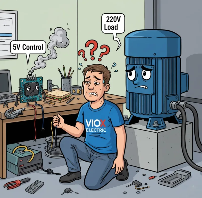
Has pasado semanas diseñando el sistema automatizado perfecto. Tal vez sea un controlador de riego inteligente para tu invernadero, un sistema transportador industrial o un centro de domótica. Tu código de Arduino es elegante, tu lógica es impecable y estás listo para conectar todo.
Entonces llega la realidad.
Tu microcontrolador entrega 5V a 40 miliamperios. Pero la bomba de agua de 220V que necesitas controlar consume 8 amperios. Intentas conectarlos con un transistor: se sobrecalienta. Intentas una conexión directa a través de un MOSFET: tu Arduino libera su humo mágico y muere una muerte $30. O peor: no pasa absolutamente nada. La carga permanece allí, burlándose de tu título de ingeniería, negándose a encenderse.
Entonces, ¿cómo salvar este enorme abismo entre las señales de control de baja potencia y las cargas industriales de alta potencia sin destruir equipos costosos o crear un peligro de seguridad?
La respuesta es más simple de lo que piensas, pero elegir la solución incorrecta puede costarte tiempo, dinero y, potencialmente, vidas. Esta guía completa te transformará de confundido a seguro al especificar, seleccionar e implementar módulos de relé para cualquier aplicación.
Por Qué Tu Microcontrolador No Puede Controlar Cargas del Mundo Real (Y Por Qué Eso Es Realmente Bueno)
Antes de adentrarnos en los módulos de relé, comprendamos por qué por qué existe este problema en primer lugar.
Tu microcontrolador típico—ya sea un Arduino,, Raspberry Pi, o un PLC industrial—está diseñado para procesar información, no para alimentar maquinaria pesada. Los pines GPIO (Entrada/Salida de Propósito General) en estos dispositivos típicamente entregan:
- Tensión: 3.3V a 5V DC
- Actual: 20-40 miliamperios máximo
- Poder: Aproximadamente 0.2 vatios
Mientras tanto, los dispositivos del mundo real demandan exponencialmente más:
- Una bomba de agua estándar: 220V CA a 5-10 amperios (1,100-2,200 vatios)
- Un motor industrial: 480V CA a 15 amperios (7,200 vatios)
- Incluso una simple lámpara doméstica: 120V CA a 0.5 amperios (60 vatios)
Las matemáticas son brutales: Tu microcontrolador puede proporcionar 0.2 vatios, pero necesita controlar dispositivos que consumen de 60 a 7,200 vatios. Eso es como intentar remolcar un carguero con una cadena de bicicleta.
Pero aquí está el problema más profundo: no se trata solo de potencia. Se trata de aislamiento y seguridad. Cuando trabajas con altos voltajes (cualquier cosa por encima de 50V CA o 120V DC), un error de cableado puede:
- Enviar 220V CA de vuelta a tu microcontrolador, vaporizándolo al instante
- Crear un camino para que voltajes peligrosos te alcancen a través de envolventes metálicas
- Causar incendios eléctricos por arqueo y sobrecalentamiento
- Violar códigos eléctricos que requieren aislamiento galvánico
Conclusión Clave: Necesitas un “traductor eléctrico”—un dispositivo que acepte pequeñas señales de control pero pueda conmutar cargas de potencia masivas, todo mientras mantiene una barrera de seguridad física entre los dos circuitos. Esto es precisamente para lo que fueron diseñados los módulos de relé.
¿Qué es un Módulo de Relé? Tu Puente Eléctrico Entre Dos Mundos
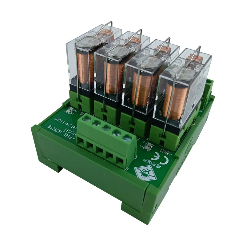
Un Un módulo de relé es una placa de circuito que alberga uno o más interruptores electromecánicos o de estado sólido, junto con componentes de soporte que protegen tanto tu circuito de control como el propio relé. Piensa en él como un puente eléctrico sofisticado con barandillas de seguridad incorporadas.
La Anatomía de un Módulo de Relé
A diferencia de un relé independiente (solo el mecanismo de conmutación), un módulo de relé es un subsistema completo que contiene:
1. El/Los Relé(s) en Sí Mismos
- Tipo electromagnético: Utiliza una bobina para crear un campo magnético que mueve físicamente los contactos (el más común)
- Tipo de estado sólido (SSR): Utiliza semiconductores para conmutar sin partes móviles (más rápido, mayor vida útil, pero más costoso)
2. Circuito de Control de Entrada
- Pines/Conectores de terminal: Donde se conecta tu señal de control de bajo voltaje (generalmente 3-4 pines: VCC, GND, Señal, a veces Habilitar)
- Buffer de entrada: Protege contra picos de voltaje desde el lado de control
3. Contactos de Potencia de Salida
- Terminales de tornillo (típicamente 3): Común (COM), Normalmente Abierto (NO) y Normalmente Cerrado (NC)
- Estos manejan la conmutación de alto voltaje y alta corriente
4. Componentes Críticos de Protección
- Diodos de retroceso (flyback): Previenen picos de voltaje cuando la bobina del relé se desenergiza (estos salvan la vida de tu microcontrolador)
- Optoacopladores: Crean aislamiento óptico entre el lado de control y el de potencia (en módulos optoaislados)
- Indicadores LED: Confirmación visual del estado del relé
- Controladores de transistor: Amplifican la débil señal de control a corriente suficiente para la bobina del relé
¿Qué lo Hace “Modular”?
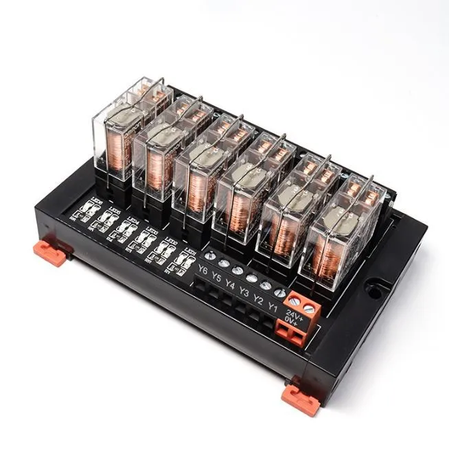
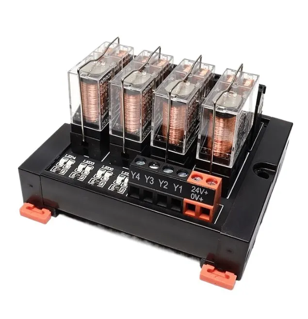
El término “módulo” es clave aquí. Estos dispositivos vienen en configuraciones estandarizadas:
- Un solo canal: Controla una carga (un relé)
- 2 canales, 4 canales, 8 canales, 16 canales: Controlan múltiples cargas independientes
- Formatos de placa: Montaje en PCB, montaje en riel DIN, tipos de zócalo enchufables
- Especificaciones de voltaje estándar: Entrada de 5V, 12V, 24V / Salida de 120V CA, 220V CA, 480V CA
Pro-Tip: Un módulo de relé NO es solo un relé soldado a una placa. Los componentes de soporte—especialmente el diodo de retroceso y el optoacoplador—son lo que previene fallos catastróficos. Intentar construir tu propio “módulo de relé” con solo un relé desnudo es como saltar en paracaídas con una sábana en lugar de un paracaídas. Podría funcionar... una vez.
¿Cómo Funciona un Módulo de Relé? La Secuencia de Conmutación Paso a Paso
Comprender el mecanismo interno le ayuda a solucionar problemas y seleccionar el módulo adecuado. Esto es lo que sucede desde el momento en que envía una señal de control:
Paso 1: Señal de control aplicada (el disparador)
Su microcontrolador envía una señal lógica ALTA (normalmente 3,3 V o 5 V) al pin de entrada del módulo de relé. Esta pequeña señal viaja a través de:
- Circuito de protección de entrada (las resistencias limitan la corriente)
- LED del optoacoplador (si está presente): convierte la señal eléctrica en luz
- Fototransistor (recibe luz, produce una señal eléctrica en el lado aislado)
- Controlador de transistor (amplifica la señal a ~50-200 mA necesarios para la bobina del relé)
Paso 2: Activación del electroimán (el músculo)
La corriente amplificada fluye a través de la bobina electromagnética del relé (normalmente de 70 a 400 ohmios de resistencia). Esto crea un campo magnético lo suficientemente fuerte como para:
- Tirar de un metal armadura (brazo móvil) hacia la bobina
- Superar la tensión del resorte que mantiene los contactos separados
- Este movimiento mecánico tarda de 5 a 15 milisegundos
Paso 3: Cierre de contacto (el interruptor)
El movimiento de la armadura provoca una de estas dos acciones:
Para la configuración normalmente abierta (NO):
- Los contactos están separados por defecto (circuito abierto)
- La armadura junta los contactos → el circuito se cierra → la energía fluye hacia la carga
Para la configuración normalmente cerrada (NC):
- Los contactos se tocan por defecto (circuito cerrado)
- La armadura separa los contactos → el circuito se abre → la energía deja de fluir
El físico espacio de aire entre los contactos (normalmente de 1 a 2 mm) proporciona un verdadero aislamiento galvánico: una separación física completa entre su circuito de control de 5 V y su circuito de alimentación de 220 V.
Paso 4: Activación de la carga (el resultado)
Una vez que los contactos se cierran, la corriente CA o CC de alto voltaje fluye a través de:
- Terminal COM (común) → recibe energía de la fuente
- Terminal NO (normalmente abierto) → se conecta a su carga
- La carga funciona (el motor gira, la luz se ilumina, el solenoide se activa, etc.)
Paso 5: Desactivación (el apagado)
Cuando elimina la señal de control (lógica BAJA), el proceso se invierte:
- La corriente deja de fluir a través de la bobina del relé
- El campo magnético colapsa
- Momento crítico: El campo magnético que colapsa genera un pico de tensión inversa (tensión de retorno) que puede alcanzar los 100 V+
- Diodo de retorno conduce inmediatamente, desviando este pico de forma segura a tierra
- La tensión del resorte tira de la armadura hacia su posición predeterminada
- Los contactos se separan → el circuito de alimentación se abre → la carga se desactiva
Pro-Tip: El diodo de retorno no es un adorno de marketing opcional, es el componente que evita que su Arduino se convierta en un costoso pisapapeles. Sin él, el pico de tensión del colapso de la bobina puede atravesar el pin de salida de su microcontrolador, destruyendo todo el IC. Verifique siempre que su módulo de relé incluya esta protección.
Tipos de módulos de relé: elección de su arma eléctrica
No todos los módulos de relé son iguales. El tipo que elija depende de las exigencias de su aplicación en cuanto a velocidad, precisión, capacidad de corriente y entorno.
1. Módulos de relé electromagnético (EMR): el caballo de batalla
Cómo funcionan: Contactos físicos movidos por una bobina electromagnética
Ventajas:
- Alta capacidad de corriente: Puede manejar de 5 A a 30 A por contacto
- Verdadero aislamiento galvánico: El espacio de aire físico proporciona una separación eléctrica completa
- Bajo costo: $2-$10 por canal de relé
- Compatibilidad universal: Funciona con cargas de CA o CC igualmente bien
- Sin problemas de disipación de calor: A diferencia de los semiconductores, los contactos no generan calor durante la conducción
Desventajas:
- Desgaste mecánico: Los contactos se degradan después de 100.000 a 1.000.000 de ciclos
- Conmutación lenta: Tiempo de respuesta de 5 a 15 ms
- Clic audible: Cada interruptor hace ruido
- Rebote de contacto: Los contactos pueden rebotar abierto/cerrado durante 1-2 ms durante la transición
- Tamaño: Más voluminosos que las alternativas de estado sólido
Mejor para: Equipos industriales, controles HVAC, arrancadores de motor, cualquier aplicación donde la capacidad de corriente y el aislamiento superen la velocidad
2. Módulos de relé de estado sólido (SSR) — El demonio de la velocidad
Cómo funcionan: Semiconductores (TRIAC, tiristores, MOSFET) conmutan sin partes móviles
Ventajas:
- Conmutación ultrarrápida: Tiempo de respuesta inferior a un milisegundo
- Funcionamiento silencioso: Cero ruido mecánico
- Larga vida útil: Sin desgaste de contacto = millones a miles de millones de ciclos
- Sin rebote de contacto: Conmutación limpia para electrónica sensible
- Compacto: Huella más pequeña que los equivalentes EMR
Desventajas:
- Generación de calor: Los semiconductores disipan 1-2 vatios incluso cuando están “encendidos”, lo que requiere disipadores de calor
- Caída de voltaje: Típicamente caída de 1-2 V a través del SSR cuando conduce (energía desperdiciada)
- Mayor costo: $10-$50+ por relé
- Sensible al tipo de carga: Algunos SSR solo funcionan con CA, otros solo con CC
- Menor tolerancia a sobretensiones: Más vulnerable a los picos de sobretensión que los contactos mecánicos
Mejor para: Conmutación de alta frecuencia (control PID, aplicaciones PWM), entornos sensibles a la temperatura donde el clic es inaceptable, aplicaciones de larga duración (> 1 millón de ciclos)
3. Módulos de relé híbridos: lo mejor de ambos mundos
Combina un relé electromagnético para la conmutación de energía con un SSR para servicio piloto o supresión de arco.
Mejor para: Aplicaciones que requieren alta capacidad de corriente y vida útil prolongada de los contactos (por ejemplo, circuitos de arranque suave de motores)
4. Configuraciones especiales
- Relés de enclavamiento: Permanecen en la última posición sin alimentación continua de la bobina (eficiencia energética para aplicaciones de batería)
- Relés de retardo de tiempo: Circuitos de temporizador incorporados para la conmutación retardada
- Relés de seguridad: Contactos redundantes con mecanismos de guía forzada (crítico para la seguridad de la máquina)
- Relés de alta frecuencia/RF: Especializados para radio y telecomunicaciones (coincidencia de impedancia de 50 Ω, pérdida de inserción mínima)
Consejo profesional: Los SSR parecen superiores en el papel: más rápidos, mayor vida útil, silenciosos. Pero son la elección incorrecta para la mayoría del control de motores industriales. ¿Por qué? La caída de voltaje crea calor, y el calor es el enemigo en un gabinete de control ya caliente. Además, los EMR manejan las sobretensiones de corriente de irrupción (6-8 veces la corriente normal cuando arrancan los motores) mucho mejor que los semiconductores. Haga coincidir el tipo de relé con la aplicación, no con la exageración de la hoja de especificaciones.
La guía completa de selección de módulos de relé: seis especificaciones críticas
Elegir el módulo de relé incorrecto es costoso: contactos quemados, cargas fallidas o circuitos de control destruidos. Siga este enfoque sistemático para especificar correctamente cada vez.
Paso 1: Determine los requisitos de su carga
Antes incluso de mirar las especificaciones del relé, caracterice a fondo su carga:
Tensión:
- ¿Cuál es el voltaje de suministro? (120 V CA, 220 V CA, 24 V CC, etc.)
- ¿Esto cambiará alguna vez? (Algunos equipos tienen capacidad de doble voltaje)
Actual:
- ¿Cuál es la corriente de funcionamiento (estado estacionario)?
- ¿Cuál es la corriente de irrupción (sobretensión de arranque)? Para los motores, esto es típicamente 6-10 veces la corriente de funcionamiento durante 100-500 ms
- ¿Cuál es la corriente de rotor bloqueado (el peor de los casos si el motor se detiene)?
Tipo de carga:
- Resistiva: Calentadores, luces incandescentes (más fáciles para los contactos)
- Inductiva: Motores, solenoides, transformadores (generan fuerza contraelectromotriz, más difíciles para los contactos)
- Capacitiva: Fuentes de alimentación, controladores LED (alta irrupción, estrés moderado)
- Cargas de lámpara: Los filamentos de tungsteno tienen una corriente de irrupción de 10 a 15 veces debido a la resistencia en frío
Ejemplo: Un motor monofásico de 1HP, 220V:
- Corriente de funcionamiento: ~6.8A (de la placa de identificación)
- Corriente de irrupción: 6.8A × 6 = ~40A durante 100ms
- Por lo tanto, necesita un relé clasificado para ≥10A continuos Y capaz de manejar una irrupción de 40A
Paso 2: Seleccione la clasificación de corriente de contacto (con margen de seguridad)
La regla de oro: Reducir la potencia en un 50% como mínimo para prolongar la vida útil
Si su carga consume 10A continuos:
- Incorrecto: Elegir un relé de 10A (fallará prematuramente)
- Correcto: Elegir un relé de 20A (los contactos durarán la vida útil nominal)
¿Por qué reducir la potencia?
- Las clasificaciones de los contactos asumen condiciones ideales (temperatura, altitud, frecuencia de conmutación específicas)
- Las condiciones del mundo real degradan el rendimiento
- La reducción de la potencia extiende la vida útil de los contactos de 100,000 ciclos a más de 500,000 ciclos
Consejo profesional: Prestar atención a Clasificaciones de CA vs CC—¡son dramáticamente diferentes! Un relé clasificado para “10A a 250V CA” podría manejar solo “5A a 30V CC”. ¿Por qué? La corriente CA cruza naturalmente por cero 100-120 veces por segundo, extinguiendo cualquier arco. La corriente CC mantiene un arco continuo, causando una severa erosión de los contactos. Siempre verifique AMBAS clasificaciones.
Paso 3: Verificar la clasificación de voltaje de conmutación
Regla: Seleccionar un relé clasificado para ≥150% de su voltaje de suministro
- Para cargas de 120V CA → relé mínimo de 180V (usar uno clasificado para 250V)
- Para cargas de 220V CA → relé mínimo de 330V (usar uno clasificado para 400V)
- Para cargas de 24V CC → relé mínimo de 36V (usar uno clasificado para 50V)
¿Por qué tal margen de seguridad? Picos de voltaje transitorios de:
- Impactos de rayos en líneas eléctricas cercanas
- Arranques de motores grandes en otras partes de la instalación
- Equipos de soldadura u otras operaciones de alta corriente
- Pueden crear breves eventos de sobrevoltaje 50-100% por encima del nominal
Paso 4: Elegir el voltaje de control (que coincida con su controlador)
Voltajes de control comunes:
- 5V: Arduino, Raspberry Pi, la mayoría de los microcontroladores para aficionados
- 3.3V: Algunos microcontroladores más nuevos, dispositivos IoT (¡verificar la compatibilidad!)
- 12V: Automotriz, PLCs industriales, sistemas alimentados por batería
- 24V: Estándar industrial (PLCs, equipos de automatización)
Verificación crítica: ¿Puede su microcontrolador fuente suficiente corriente?
La bobina de relé típica consume 50-200mA
Pines de Arduino: 40mA máximo (¡INSUFICIENTE para accionamiento directo!)
Solución: Usar un módulo de relé con circuito de controlador de transistor (la mayoría de los módulos comerciales incluyen esto)
Paso 5: Determinar el número de canales
¿Cuántas cargas independientes necesita controlar?
- Un solo canal: Una carga (más simple, menor costo)
- 2/4 canales: Múltiples cargas, uso eficiente del espacio
- 8/16 canales: Sistemas de automatización, paneles de control
Consideración: Incluso si solo necesita 3 relés ahora, comprar un módulo de 4 canales podría ser más rentable que tres individuales, y le brinda capacidad de expansión.
Paso 6: Seleccionar características especiales (si es necesario)
- Opto-aislamiento: Crea una barrera óptica entre los lados de control y potencia
- Esencial para: entornos industriales ruidosos, sistemas críticos para la seguridad, tendidos de cables largos
- Agrega $1-$5 por canal, pero proporciona una inmunidad al ruido superior
- LEDs indicadores: Confirmación visual del estado del relé
- Invaluables para la resolución de problemas
- Estándar en la mayoría de los módulos de calidad
- Estilo de montaje:
- Montaje en PCB: Instalaciones permanentes, desarrollo de productos
- Montaje en riel DIN: Gabinetes industriales, fácil acceso para mantenimiento
- Montaje en zócalo: Relés enchufables, capacidad de reemplazo rápido
Errores comunes del módulo de relé que le costarán (y cómo evitarlos)
Error común #1: Ignorar la corriente de irrupción
El escenario: Especifica un relé para un motor de 5A basándose en la corriente de funcionamiento nominal. Los contactos del relé se sueldan después de 2 semanas.
La Realidad: La corriente de irrupción del motor fue de 30A durante 100ms al arrancar. Los contactos no estaban clasificados para esta sobretensión.
La Corrección: Siempre multiplique la FLA (Amperios a plena carga) del motor por 6-8 para la corriente de irrupción, y elija un relé clasificado para este pico—o use un circuito de arranque suave para limitar la corriente de irrupción.
Error común #2: Usar clasificaciones de CC para cargas de CA (o viceversa)
El escenario: Su relé de “10A” falla al controlar un solenoide de CC de 5A.
La Realidad: La clasificación de 10A era solo para CA. La clasificación de CC era de 3A.
La Corrección: Consulte la hoja de datos para las clasificaciones de CA y CC. Pueden diferir en un 50-200%.
Error común #3: Falta de protección con diodo flyback
El escenario: Su Arduino se reinicia aleatoriamente o deja de responder después de activar los relés.
La Realidad: Los picos de voltaje flyback de la desenergización de la bobina del relé están corrompiendo el microcontrolador o destruyendo los pines de salida.
La Corrección: Siempre use módulos de relé con diodos flyback integrados. Si debe usar un relé desnudo, agregue un diodo 1N4007 a través de la bobina (cátodo a positivo).
Error común #4: Subdimensionamiento del calibre del cable
El escenario: Su relé correctamente clasificado aún falla o causa problemas de caída de voltaje.
La Realidad: Usó cable de 22 AWG para una carga de 15A. El cable es el cuello de botella.
La Corrección: Siga las tablas de capacidad de corriente del cable:
- Carga de 10A → 18 AWG mínimo
- Carga de 15A → 14 AWG mínimo
- Carga de 20A → 12 AWG mínimo
Error común #5: Descuidar el material de contacto para su aplicación
La Realidad: No todos los contactos del relé son iguales:
- Óxido de plata-cadmio: Propósito general, bueno para la mayoría de las cargas
- Óxido de plata-estaño: Cargas de motor, alta tolerancia a la corriente de irrupción
- Oro: Conmutación de señales de baja potencia (miliamperios), NO para cargas de potencia
La Corrección: Haga coincidir el material de contacto con el tipo de carga; consulte las especificaciones de la hoja de datos.
Ejemplos de Aplicaciones en el Mundo Real
Ejemplo 1: Control de iluminación para el hogar inteligente
Desafío: Controlar 8 luces domésticas (120V CA, 60W cada una) con una Raspberry Pi (3.3V GPIO).
Solución:
- Módulo de relé de 8 canales y 5V con optoaislamiento
- Cada canal clasificado para 10A a 250V CA (60W ÷ 120V = 0.5A, margen de seguridad masivo)
- Carga resistiva (incandescente) = fácil para los contactos
- Costo total: ~20€ por el módulo
Ejemplo 2: Control de motor de transportador industrial
Desafío: Arrancar/detener un motor trifásico de 2HP, 220V con un PLC (salida de 24V CC).
Solución:
- Módulo de relé industrial de un solo canal de 24V, montaje en carril DIN
- Clasificación de contacto: 25A a 480V CA (el motor consume 8A en funcionamiento, 48A en irrupción)
- Contactos de óxido de plata-estaño para servicio de motor
- Indicador LED incorporado para visibilidad del mantenimiento
- Costo: ~45€, pero previene eventos de tiempo de inactividad de más de 5,000€
Ejemplo 3: Sistema de riego Arduino
Desafío: Controlar 4 electroválvulas (24V CA, 0.5A cada una) con Arduino (5V).
Solución:
- Módulo de relé de 4 canales y 5V
- Clasificación de 10A por canal (gran margen de seguridad para válvulas de 0.5A)
- Costo: ~8€
- Crítico: Cada solenoide es una carga inductiva, por lo que los diodos flyback en el módulo son esenciales
Conclusión: Su lista de verificación de especificaciones del módulo de relé
Un módulo de relé es su puente esencial entre la inteligencia de control de baja potencia y la acción del mundo real de alta potencia. Siguiendo este enfoque sistemático, especificará el módulo correcto cada vez:
Antes de comprar:
- Calcule la corriente de funcionamiento y la corriente de irrupción para su carga
- Verifique que las clasificaciones de CA y CC coincidan con su aplicación
- Reduzca las clasificaciones de contacto en un 50% para prolongar la vida útil
- Confirme que el voltaje de control coincida con su microcontrolador
- Verifique la protección del diodo flyback y el optoacoplador
- Seleccione el estilo de montaje apropiado para su instalación
- Considere las necesidades de expansión futuras (canales adicionales)
Resumen de conclusiones clave:
- El aislamiento lo es todo: Nunca comprometa la separación física/óptica entre el control y la potencia
- La corriente mata los contactos: Subestimar la capacidad de corriente es la causa principal del fallo prematuro del relé.
- La protección no es opcional: Los diodos flyback salvan tu microcontrolador; la correcta protección con fusibles salva tus instalaciones.
- Utiliza la herramienta adecuada para el trabajo: Relés electromecánicos (EMR) para potencia, relés de estado sólido (SSR) para velocidad, optoaislamiento para inmunidad al ruido.
Tu próximo paso: Antes de hacer clic en “Añadir al carrito”, consulta la hoja de datos y verifica cada especificación con respecto a los requisitos reales de tu carga. Los 10 minutos que inviertas ahora te ahorrarán horas de solución de problemas y cientos de dólares en equipos quemados.
¿Tienes preguntas sobre una aplicación específica de un módulo de relé? El modo de fallo más común es elegir basándose únicamente en el voltaje, ignorando la capacidad de corriente y el tipo de carga; no permitas que esta sea tu costosa lección aprendida.
