Auf dieser Seite
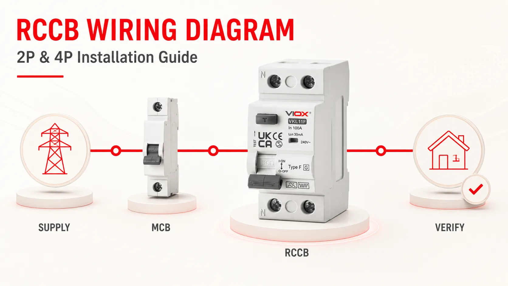
Um einen FI-Schutzschalter korrekt anzuschließen, führen Sie jeden stromführenden Leiter, der den geschützten Stromkreis versorgt, durch denselben FI-Schutzschalter. In einem einphasigen Stromkreis bedeutet dies normalerweise die Führung von Außenleiter und Neutralleiter durch einen 2-poligen FI-Schutzschalter. In einem dreiphasigen Vierleiter-Stromkreis bedeutet dies die Führung von L1, L2, L3 und Neutralleiter durch einen 4-poligen FI-Schutzschalter. Der Schutzleiter (PE) wird direkt mit der PE-Schiene verbunden; er darf nicht durch einen Pol des FI-Schutzschalters geführt werden.
Ein FI-Schutzschalter muss zudem mit einer separaten Überstromschutzeinrichtung koordiniert werden, da er keinen integrierten Überlast- oder Kurzschlussschutz bietet. Nach der Installation müssen die Verdrahtung und die Schutzmaßnahmen gemäß den geltenden örtlichen Vorschriften geprüft und getestet werden. Die frontseitige TEST-Taste allein stellt keine vollständige Überprüfung dar.
Sicherheit und Geltungsbereich: Arbeiten an fest installierten Verteilern können Personal Gefahren durch Stromschlag, Lichtbögen, Rückspeisung und hohe Fehlerenergien aussetzen. Die Installation und die Prüfung unter Spannung eines FI-Schutzschalters dürfen nur von einer Elektrofachkraft unter Anwendung eines zugelassenen sicheren Arbeitssystems durchgeführt werden. Die nachstehenden Diagramme erläutern die Anschlussprinzipien; das auf dem jeweiligen FI-Schutzschalter aufgedruckte Diagramm, dessen Installationsanleitung, die Anforderungen des Schaltschrankherstellers sowie die örtlichen Vorschriften haben Vorrang.
RCCB-Verdrahtung auf einen Blick
| Schaltung | Typischer RCCB | Leiter durch den RCCB | Leiter außerhalb des RCCB | Separater Schutz erforderlich |
|---|---|---|---|---|
| Einphasig, Außenleiter + Neutralleiter | 2-poliger RCCB | L und N | PE- | MCB, MCCB oder Sicherung gemäß Auslegung |
| Dreiphasig, 4-Leiter | 4-poliger RCCB | L1, L2, L3 und N | PE- | MCB, MCCB oder Sicherung gemäß Auslegung |
| Dreiphasig, 3-Leiter | Produktspezifisch | Alle drei Phasen unter Verwendung der vom Hersteller zugelassenen Anordnung | PE- | MCB, MCCB oder Sicherung gemäß Auslegung |
Schließen Sie nicht von der physischen Oberseite des Geräts auf die Einspeiseseite. Einige Fehlerstromschutzschalter (RCCBs) geben eine Leitungs- und Lastrichtung vor; andere erlauben mehr als eine Anordnung. Der interne TEST-Stromkreis kann ebenfalls von bestimmten Anschlüssen abhängen. Befolgen Sie immer die Kennzeichnungen und Anweisungen für die genaue Katalognummer.
Wenn Sie zuerst die Grundlagen des Geräts benötigen, lesen Sie Was ist ein RCCB?. Der Rest dieses Leitfadens konzentriert sich auf die Verdrahtung und die Installationsprüfung.
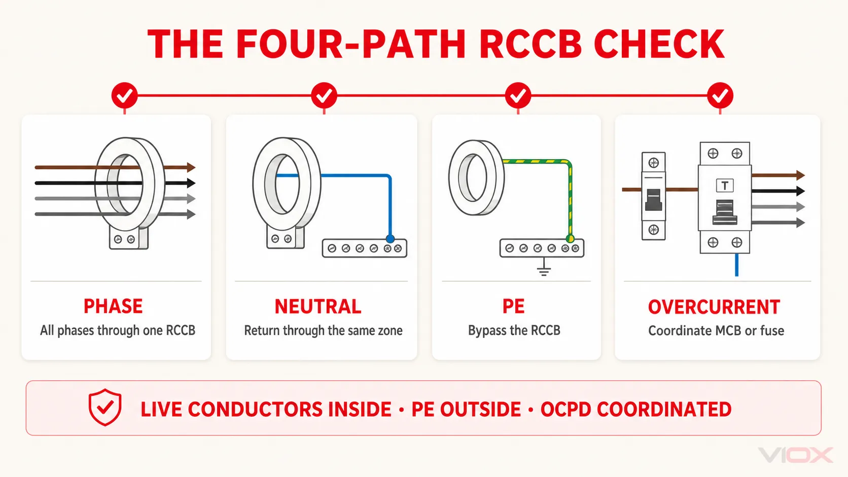
Die Vier-Pfad-Verdrahtungsprüfung für RCCBs
Ein RCCB-Schaltplan lässt sich leichter überprüfen, wenn er in vier Strompfade unterteilt wird.
1. Phasenpfad
Jede Phase, die den geschützten Verbraucher versorgt, muss einmal durch das Messsystem desselben FI-Schutzschalters (RCCB) geführt werden. Eine Phase, die den RCCB umgeht, macht die beabsichtigte Messung wirkungslos; ein falsch durch den Messpfad geführter Leiter kann zudem ungewollte Auslösungen verursachen.
Neutralleiterpfad
Wenn ein Neutralleiter verwendet wird, muss der zum geschützten Stromkreis gehörende Neutralleiter durch den korrekten RCCB geführt werden und darf nur über den nachgeschalteten Neutralleiterbereich dieses RCCB zurückkehren. Ein gemeinsamer Neutralleiter, ein entlehnter Neutralleiter oder der Anschluss an die falsche Neutralleiterschiene kann dazu führen, dass der normale Laststrom als Fehlerstrom interpretiert wird.
Schutzleiterpfad (PE)
Der PE verbindet die berührbaren leitfähigen Teile des Verbrauchers mit dem Schutzleitersystem der Anlage. Er muss durchgehend sein und darf nicht durch den Mess- und Schaltpfad des RCCB geführt werden. Verwenden Sie niemals einen Pol des RCCB zum Schalten des PE.
Überstrompfad
Ein RCCB erkennt eine Fehlerstrom-Unsymmetrie. Ein koordinierter Leitungsschutzschalter (MCB), Kompaktleistungsschalter (MCCB) oder eine Sicherung muss den Stromkreis und den RCCB vor Überlast und Kurzschluss schützen. Bei der Auswahl müssen der Bemessungsstrom, die Leiterkapazität, Derating-Faktoren, der prospektive Kurzschlussstrom sowie die vom Hersteller angegebene Vorsicherung oder bedingte Kurzschlussfestigkeit berücksichtigt werden – es reicht nicht aus, lediglich zwei Ampere-Werte zu vergleichen.
Diese vier Pfade bilden eine schnelle Prüfregel: Alle vorgesehenen aktiven Leiter innerhalb der Fehlerstromschutzzone, PE außerhalb, und Überstromschutz im gesamten Stromkreis.
Wo wird der FI-Schutzschalter (RCCB) im Verteiler eingebaut?
Eine übliche Gruppenabsicherung sieht wie folgt aus:
EinspeisungBei dieser Anordnung befindet sich der RCCB vor den LS-Schaltern, die er schützt. Die Aussage “der RCCB muss immer vor jedem LS-Schalter sitzen” ist jedoch zu allgemein. Ein Verteiler kann stattdessen einen RCBO pro Endstromkreis, eine aufgeteilte Lastanordnung, mehrere RCCB-Zonen oder eine geprüfte Baugruppe mit einer anderen physischen Reihenfolge verwenden.
Die Auslegungsfrage ist nicht einfach, welches Gerät zuerst auf der DIN-Schiene erscheint. Stellen Sie sicher, dass:
- der Fehlerstromschutz den vorgesehenen Stromkreis abdeckt;
- Überlast- und Kurzschlussschutz vorhanden und koordiniert sind;
- Jede FI-Schutzschalter-Zone verfügt über eine korrekte Neutralleiterführung;
- die Schutzkombination ist für den verfügbaren Fehlerstrom geeignet;
- die Selektivität zwischen vor- und nachgeschalteten RCDs ist dort berücksichtigt, wo die Versorgungssicherheit entscheidend ist; und
- der Aufbau und die Sammelschienenanordnung sind für die verwendeten Geräte zugelassen.
Vergleichen Sie für die Architekturentscheidung FI-Schutzschalter (RCCB) + Leitungsschutzschalter (MCB) gegenüber FI/LS-Schalter (RCBO).
Prüfungen vor der Installation eines FI-Schutzschalters (RCCB)
Beginnen Sie nicht mit einem allgemeinen Anschlussplan. Identifizieren Sie zuerst den tatsächlichen Stromkreis und das Gerät.
| Prüfen | Vor der Verdrahtung bestätigen | Warum es wichtig ist |
|---|---|---|
| Versorgung | Spannung, Frequenz, Phasenanzahl, Verfügbarkeit des Neutralleiters, Erdungskonzept und alle möglichen Quellen | Bestimmt die Polnutzung und den sicheren Trennbereich |
| Identität des Fehlerstromschutzschalters (RCCB) | Katalog-Nummer, 2P/4P, Bemessungsstrom Unter, Bemessungsfehlerstrom IΔn, Typ AC/A/F/B und Zeitverzögerungscharakteristik |
Verhindert die Installation der falschen Schutzfunktion |
| Anschlussplan | Vorgesehene Einspeise-/Lastseite, Neutralleiterpol, zulässige Einspeiserichtung sowie alle zugelassenen 3-Leiter-Anschlüsse | Allgemeine Anschlussbezeichnungen sind nicht universell gültig |
| Leiter | Material, Querschnitt, Vorbereitung, Anschlusskapazität sowie Anforderungen an Aderendhülsen oder Kabelschuhe | Zuverlässigkeit und Erwärmung von Steuerleitungsanschlüssen |
| Drehmoment | Exaktes Anzugsdrehmoment und Werkzeuganforderungen gemäß Produktdokumentation | Sowohl zu geringes als auch zu hohes Anzugsdrehmoment kann eine Verbindung beschädigen |
| Überstromkoordination | Vorgeordnetes Überstromschutzorgan (OCPD), Bemessungsstrom, prospektiver Kurzschlussstrom und deklarierter Backup-Schutz | Ein Fehlerstromschutzschalter (RCCB) besitzt keinen integrierten Überstromschutz |
| Verteilersystem | Tragschiene (DIN-Schiene), Sammelschienenkompatibilität, Gehäuseplatz, Wärmeabfuhr, Trennwände und Herstellervorgaben | Das Gerät ist Teil einer Baugruppe, keine eigenständige Komponente |
| Prüfplan | Erforderliche spannungsfreie Prüfungen, Spannungsprüfungen, Eignung des RCD-Prüfgeräts, Dokumentation und lokale Abnahmekriterien | Die Prüfung muss auf das installierte Gerät und die geltenden Vorschriften abgestimmt sein |
Auswahl der Empfindlichkeit und des Fehlerstromtyps basierend auf Last, Schutzziel, erwartetem Ableitstrom, lokalen Vorschriften und Geräteanweisungen. Eine 30-mA-Kennzeichnung steht für einen Bemessungsfehlerstrom von 0,03 A; dies bedeutet nicht, dass 30 mA der normale Laststrom-Bemessungswert des RCCB ist. Siehe die Auswahlleitfaden für die Empfindlichkeit von Fehlerstrom-Schutzschaltern (RCCB) für diese Entscheidung.
Sichere Trennung vor der Verdrahtung des FI-Schutzschalters
Die qualifizierte Person sollte das vor Ort genehmigte Trennverfahren und die geltenden nationalen Vorschriften befolgen und dabei ein sicheres Arbeitssystem anwenden, wie es in den Grundsätzen beschrieben ist in HSE HSG85. Der Plan muss mindestens die Netzversorgung sowie alle Generatoren, USV-Anlagen, Photovoltaikanlagen, Steuertransformatoren, gekoppelten Stromkreise oder andere mögliche Rückspeisungen berücksichtigen.
Eine typische sichere Arbeitsabfolge besteht darin:
- den korrekten Stromkreis, die Ausrüstung und jede Quelle zu identifizieren;
- Lasten bei Bedarf abzuschalten;
- Spannungsversorgung mit geeigneten Vorrichtungen trennen;
- Trennstelle gegen Wiedereinschalten sichern und erforderliche Warnhinweise anbringen;
- Spannungsprüfer auf Funktion prüfen;
- Spannungsfreiheit an allen relevanten Leitern an der Arbeitsstelle feststellen; und
- Spannungsprüfer erneut auf Funktion prüfen.
Verlassen Sie sich nicht auf die Griffstellung, Kontrollleuchten, berührungslose Spannungsprüfer oder den FI-Schutzschalter (RCCB) selbst als Nachweis der Spannungsfreiheit. Wenn benachbarte Anlagenteile unter Spannung bleiben, können zusätzliche Barrieren und Vorsichtsmaßnahmen erforderlich sein. Wenn die Arbeiten nicht im spannungsfreien Zustand durchgeführt werden können, ist eine separate, begründete Gefährdungsbeurteilung für Arbeiten unter Spannung erforderlich; dieser Artikel bietet eine solche nicht.
Schaltplan für einen 2-poligen FI-Schutzschalter (RCCB) für einphasige Stromkreise
Die folgende Anordnung für einen einzelnen Stromkreis verwendet einen 1-poligen Leitungsschutzschalter (MCB) im Außenleiterpfad vor einem 2-poligen FI-Schutzschalter (RCCB). Hier dient der MCB als vorgeschaltete Überstromschutzeinrichtung für einen Endstromkreis; dies unterscheidet sich von der oben genannten Gruppenanordnung, bei der ein FI-Schutzschalter mehrere nachgeschaltete Abzweig-Leitungsschutzschalter versorgt. Der MCB bietet den ausgelegten Überstromschutz, sowohl der Außenleiter als auch der Neutralleiter werden durch den FI-Schutzschalter geführt, und der Schutzleiter (PE) wird an beiden Geräten vorbeigeführt.
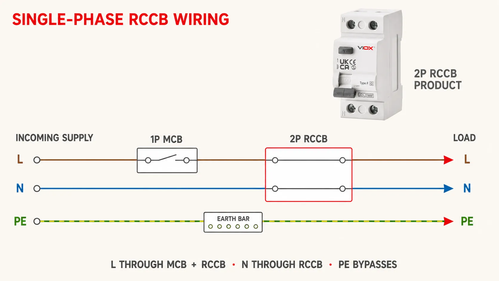
Das Diagramm zeigt die Strompfade, nicht die universellen Anschlussbelegungen:
2-POLIGER FI-SCHUTZSCHALTER (RCCB).Einphasige Anschlussreihenfolge
- Überprüfen Sie die gekennzeichneten Einspeise- und Lastklemmen am jeweiligen FI-Schutzschalter sowie die zugelassene Reihenfolge der Schutzeinrichtungen.
- Verbinden Sie die Phasenleitung der Quelle über den 1P LS-Schalter mit der gekennzeichneten Einspeiseklemme des FI-Schutzschalters.
- Verbinden Sie den Neutralleiter der Quelle direkt mit der gekennzeichneten Neutralleiter-Einspeiseklemme des FI-Schutzschalters.
- Verbinden Sie die lastseitige Phasenanschlussklemme des FI-Schutzschalters mit der geschützten Last oder dem nachgeschalteten Abzweiggerät gemäß dem zugelassenen Schaltplan.
- Verbinden Sie den nachgeschalteten Neutralleiter mit der für diesen FI-Schutzschalterbereich vorgesehenen Neutralleiterschiene.
- Verbinden Sie den Neutralleiter jedes geschützten Stromkreises ausschließlich mit der dafür vorgesehenen Sammelschiene.
- Schließen Sie die PE-Leiter an die PE-Sammelschiene an, außerhalb der RCCB-Pole.
- Überprüfen Sie den korrekten Sitz der Leiter, die Isolationsabstände, die Kennzeichnungen, die Trennwände sowie das Anzugsdrehmoment der Klemmen gemäß den Produktanweisungen.
Die physische Anordnung von RCCB und nachgeschalteten MCBs muss dem genehmigten Schaltplan entsprechen. Improvisieren Sie nicht mit Phasenschienen, Gabelkabelschuhen oder zwei Leitern in einer Klemme, es sei denn, die Klemmen- und Montageunterlagen lassen dies ausdrücklich zu.
Schaltplan für 4-poligen RCCB bei Drehstromkreisen
Bei einer Drehstromlast mit Neutralleiter werden normalerweise alle vier spannungsführenden Leiter durch einen 4-poligen RCCB geführt:
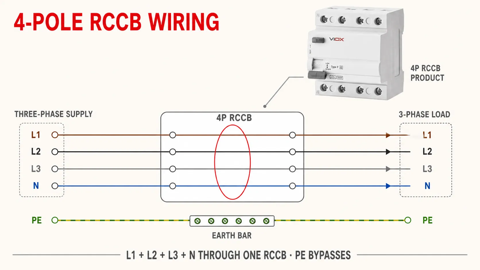
4-POLIGER RCCB ABGANGSSEITIG.Behalten Sie die Leiterkennzeichnung bei und verwenden Sie den markierten Neutralleiterpol. Wenn die Last oder die zugehörige Ausrüstung von der Phasenfolge abhängig ist, überprüfen Sie die Phasenfolge gemäß dem zugelassenen Inbetriebnahmeprotokoll.
Was ist, wenn der Drehstromkreis keinen Neutralleiter hat?
Kopieren Sie kein allgemeines Drei-Leiter-Schaltbild auf einen 4-poligen FI-Schutzschalter (RCCB). Einige Geräte erlauben einen dokumentierten 3P-Anschluss ohne Neutralleiter, da ihr TEST-Stromkreis zwischen den Phasen versorgt wird. Andere Konstruktionen erfordern eine bestimmte Polanordnung, Brücke, Hilfsspannung oder einen Neutralleiter für die korrekte Funktion. Ein Anschluss, der die Last erfolgreich führt, kann dennoch dazu führen, dass die interne Test- oder elektronische Erkennungsfunktion falsch versorgt wird.
Verwenden Sie nur die für den jeweiligen FI-Schutzschalter veröffentlichte Anordnung ohne Neutralleiter. Zum Beispiel veröffentlicht Schneider Electric eine modellspezifische 4-polige FI-Schutzschalter-Verbindung für ein Drehstromsystem ohne Neutralleiter; diese Anordnung darf nicht auf andere Geräte verallgemeinert werden. Wenn die Anleitung keine solche zeigt, holen Sie eine Bestätigung vom Hersteller ein oder wählen Sie ein geeignetes Gerät, anstatt zu improvisieren.
Installation eines FI-Schutzschalters in einem Verteiler
Sobald das Schaltungsdesign und die sichere Trennung festgelegt sind, folgt die physische Installation einer kontrollierten Abfolge.
1. Überprüfen Sie das Gerät anhand des Entwurfs
Überprüfen Sie die Polzahl, die Bemessungsspannung und die Frequenz, Unter, IΔn, den Fehlerstromtyp, das selektive oder unverzögerte Auslöseverhalten, die Umgebungsbedingungen und die Produktnorm. Stellen Sie sicher, dass es sich bei dem Gerät um einen RCCB und nicht um einen RCBO handelt.
2. Montage des RCCB
Befestigen Sie das Gerät in der vorgeschriebenen Ausrichtung auf der spezifizierten DIN-Schiene oder dem Paneelsystem. Überprüfen Sie die Abstände, die Belüftung, die Ausrichtung der Sammelschienen, den Zugang zu den Klemmen sowie die Kompatibilität mit benachbarten Geräten und Zubehörteilen.
3. Vorbereitung der Leiter
Verwenden Sie das vom Hersteller zugelassene Leitermaterial, den Querschnitt, die Abisolierlänge, Aderendhülsen und Kabelschuhe. Entfernen Sie nur so viel Isolierung wie für die Klemme erforderlich. Vermeiden Sie lose Litzen und achten Sie darauf, dass keine Isolierung in die stromführende Klemme gelangt.
4. Anschluss der überwachten Leiter
Führen Sie jede Phase und den zugehörigen Neutralleiter in der dokumentierten Richtung von der Einspeisung zur Last durch die zugewiesenen RCCB-Pole. Halten Sie die Leiter jeder RCD-Zone identifizierbar. Schalten Sie RCCB-Pole nicht parallel und verwenden Sie keine freien Pole in einer nicht vorgesehenen Anordnung.
Neutralleiter und PE korrekt anschließen
Den nachgeschalteten Neutralleiter an die dafür vorgesehene Neutralleiterschiene oder Lastklemme anschließen. Den PE direkt an die PE-Schiene anschließen. Sicherstellen, dass keine nachgeschaltete Neutralleiter-Erde-Verbindung, kein gemeinsamer Neutralleiter und keine Querverbindungen zwischen RCD-Zonen bestehen.
Mit dem dokumentierten Drehmoment festziehen
Das für das Produkt angegebene Drehmoment und ein geeignetes Werkzeug verwenden. Es gibt keinen sicheren universellen Drehmomentwert für RCCBs. Nach dem Festziehen die vorgeschriebene Zug- oder Sichtprüfung durchführen, ohne den Anschluss zu beeinträchtigen.
Barrieren und Kennzeichnungen wieder anbringen
Klemmenabdeckungen, Frontplatten, Blindabdeckungen und Gehäusedeckel wieder installieren. Die geschützten Stromkreise, die RCCB-Zone, die Testfunktion und den Trennpunkt gemäß den Installationsvorschriften kennzeichnen.
Neutralleiter- und Erdungsregeln zur Vermeidung der meisten RCCB-Probleme
| Regel | Korrekte Anordnung | Was passiert, wenn dies ignoriert wird |
|---|---|---|
| Den Neutralleiter jedes RCCB nachgeschaltet hinter diesem RCCB führen | Geschützte Stromkreise führen zum jeweils zugehörigen Neutralleiteranschluss zurück | Normaler Rückstrom umgeht den Sensor und löst eine Abschaltung aus |
| Niemals einen Neutralleiter von einem anderen Stromkreis abgreifen | Außenleiter und der zugehörige Neutralleiter verbleiben in derselben Fehlerstromzone | Der Laststrom ist innerhalb keines der beiden RCCBs ausgeglichen |
| PE außerhalb aller stromführenden Pole halten | Der PE verläuft direkt durch das Schutzleitersystem | Das Schalten oder Unterbrechen des PE kann einen kritischen Schutzpfad aufheben |
| Fügen Sie keine nachgeschaltete N-PE-Verbindung hinzu | Neutralleiter und PE bleiben gemäß Systemdesign getrennt | Neutralleiterstrom kann sich auf den PE aufteilen und eine Fehlerstrom-Unsymmetrie erzeugen |
| Führen Sie jeden stromführenden Leiter durch denselben FI-Schutzschalter (RCCB) | L/N oder L1/L2/L3/N werden gemeinsam überwacht | Ein überbrückter Leiter hebt die Stromsummenbildung auf |
Wenn ein PEN-Leiter vorhanden ist, darf dieser nicht als Neutralleiter durch den FI-Schutzschalter (RCCB) geführt oder geschaltet werden. Der FI-Schutzschalter darf gemäß den geltenden Installationsvorschriften nur in dem Teil des Systems installiert werden, in dem Neutralleiter und Schutzleiter (PE) getrennt sind.
Die Funktion des FI-Schutzschalters hängt nicht von einem normalen Laststrom ab, der durch den Schutzleiter fließt; er misst das Ungleichgewicht zwischen den überwachten stromführenden Leitern. Dies nicht entbindet nicht von der Notwendigkeit einer Schutzerdung. FI-Schutzschalter und Schutzerdung erfüllen unterschiedliche Funktionen und beide müssen den Installationsvorgaben entsprechen.
FI-Schutzschalter (RCCB) + Leitungsschutzschalter (MCB) oder FI/LS-Schalter (RCBO)?
Beide Architekturen können einen Fehlerstrom- und Überstromschutz bieten, verteilen jedoch Risiko und Platzbedarf unterschiedlich.
| Architektur | Praktischer Vorteil | Wesentlicher Zielkonflikt |
|---|---|---|
| Ein FI-Schutzschalter versorgt mehrere Leitungsschutzschalter | Weniger Fehlerstrom-Schutzeinrichtungen und potenziell geringere Komponentenkosten | Ein Fehlerstrom kann mehrere Stromkreise abschalten; die Trennung des Neutralleiters ist entscheidend |
| Ein RCBO pro Endstromkreis | Die Fehlerisolierung ist in der Regel auf einen Stromkreis begrenzt; einfachere Zuordnung des Neutralleiters | Mehr Geräte und möglicherweise mehr Platzbedarf im Verteiler oder höhere Kosten |
Verwenden Sie die Architektur, die durch lokale Vorschriften, Anforderungen an die Kontinuität, Bewertung der Ableitströme, Selektivitätsplanung und das Design der Verteilung vorgegeben ist. Lösen Sie Fehlauslösungen nicht allein durch Erhöhung IΔn; identifizieren Sie zuerst den Ableitstrom des Stromkreises, die Lastcharakteristik, Verdrahtungsfehler und das Schutzziel.
Inbetriebnahme und Überprüfung nach der Installation
Die Installationsprüfung ist mehr als nur das Einschalten des RCCB. Die genaue Abfolge und die Grenzwerte ergeben sich aus den geltenden nationalen Vorschriften, der Projektdokumentation, den Geräteanweisungen und der Kompetenz des Prüfers. IEC 60364-6 bietet den internationalen Rahmen für die Erst- und wiederkehrende Prüfung von Niederspannungsanlagen.
Sicht- und Spannungsfreiheitsprüfung
Vor dem Einschalten ist zu prüfen:
- ob der korrekte RCCB-Typ und die Bemessungswerte installiert sind;
- ob die Leiter mit dem Stromlaufplan und dem Anschlussplan übereinstimmen;
- ob alle aktiven Leiter des geschützten Stromkreises durch den korrekten RCCB geführt sind;
- ob die nachgeschaltete Neutralleiterschiene ausschließlich zu diesem RCCB-Bereich gehört;
- Die PE-Durchgängigkeit und die N-PE-Trennung sind für das System korrekt;
- Die Anschlüsse sind mit dem dokumentierten Drehmoment festgezogen;
- Die Überstrom- und Kurzschlusskoordination entspricht der Auslegung; und
- Abdeckungen, Trennwände, Kennzeichnungen und Gehäuseschutz sind wiederhergestellt.
Führen Sie die erforderlichen Prüfungen auf Durchgängigkeit, Isolationswiderstand, Polarität und andere spannungsfreie Messungen unter Verwendung von Verfahren durch, die für angeschlossene elektronische Geräte geeignet sind.
Funktionstest der TEST-Taste
Nachdem die Installation gemäß dem genehmigten Verfahren sicher unter Spannung gesetzt wurde, betätigen Sie die TEST-Taste des RCCB unter den vom Hersteller angegebenen Bedingungen. Der RCCB muss auslösen und die entsprechenden Leiter trennen.
Die Taste prüft einen internen Betriebspfad und den Auslösemechanismus. Sie weist nicht die Durchgängigkeit des Schutzleiters, den Isolationswiderstand, die korrekte Polarität, das Fehlen von vermischten Neutralleitern oder die gemessene Auslöseleistung der gesamten Installation nach. Ein fehlgeschlagener Tastentest kann auch auf eine falsche Versorgungsspannung oder einen falschen produktspezifischen Anschluss zurückzuführen sein; schalten Sie das Gerät daher spannungsfrei und untersuchen Sie die Ursache, anstatt das Gerät wiederholt zu betätigen.
Überprüfung der Messgeräte
Wo erforderlich, sollte eine qualifizierte Person geeignete RCD-Prüfgeräte und das lokale Prüfverfahren verwenden, um die Wirksamkeit der installierten Schutzmaßnahme zu bestätigen. Das Prüfgerät, die Wellenformeinstellung, der Prüfpunkt, die angeschlossenen Lasten und die Abnahmekriterien müssen dem RCCB-Typ und den geltenden Vorschriften entsprechen. IEC 61557-6 deckt Messgeräte ab, die zur Prüfung der RCD-Wirksamkeit in installierten Systemen verwendet werden; sie ersetzt nicht die geltenden Errichtungsvorschriften.
Dokumentieren Sie die Geräteidentifikation, den Stromkreis, IΔn, die Prüfbedingungen, die Ergebnisse, das Datum und den Prüfer. Wenn der RCCB oder die Installation die erforderlichen Prüfungen nicht besteht, ist der betroffene Stromkreis außer Betrieb zu lassen, bis der Fehler behoben und die Überprüfung wiederholt wurde.
Für regelmäßige Überprüfungen und eine tiefergehende Fehlerdiagnose verwenden Sie bitte den separaten Leitfaden zur Prüfung und Wartung von RCCBs.
Häufige Fehler bei der Verdrahtung von Fehlerstromschutzschaltern (RCCB)
| Fehler | Typisches Ergebnis | Korrekturmaßnahme |
|---|---|---|
| Anschluss der Einspeisung an der falschen Seite eines richtungsabhängigen Geräts | Die TEST-Funktion funktioniert möglicherweise nicht oder der Schutz löst nicht wie vorgesehen aus | Befolgen Sie exakt das Anschluss- bzw. Lastdiagramm |
| Neutralleiter umgeht den RCCB | Sofortige oder lastabhängige Auslösung; unvollständiger Schutz | Führen Sie den zugehörigen Neutralleiter durch den korrekten Pol und Neutralleiterbereich |
| Vermischung der Neutralleiter zwischen zwei RCCBs | Eines oder beide Geräte lösen aus, wenn Lasten in Betrieb sind | Nachgeschaltete Neutralleiterschienen und Stromkreise trennen und identifizieren |
| N-PE-Verbindung auf der Abgangsseite | Normaler Neutralleiterstrom fließt teilweise über den Schutzleiter (PE) zurück | Die unbeabsichtigte Verbindung gemäß dem zugelassenen Verfahren lokalisieren und entfernen |
| Schutzleiter (PE) durch einen Pol geführt | Die Durchgängigkeit des Schutzleiters kann geschaltet oder unterbrochen sein | Schutzleiter (PE) direkt an die PE-Schiene anschließen |
| Nur einige Phasenleiter führen durch einen 4-poligen FI-Schutzschalter | Stromsummenbildung ist fehlerhaft | Alle spannungsführenden Leiter gemäß dem zugelassenen Schaltplan verlegen |
| Allgemeiner 3-Phasen-Anschluss ohne Neutralleiter verwendet | Interner Test-/Elektronikschaltkreis wird möglicherweise falsch versorgt | Modellspezifischen Schaltplan ohne Neutralleiter verwenden |
| Kein koordinierter Überstromschutz (OCPD) vorhanden | FI-Schutzschalter und Leiter weisen keinen korrekten Überlast-/Kurzschlussschutz auf | Bereitstellung des ausgelegten LS-Schalters (MCB), Kompaktleistungsschalters (MCCB) oder der Sicherung sowie Überprüfung der Fehlerstrom-Koordination |
| Geschätztes Anzugsdrehmoment der Klemmen | Lose Verbindung, Überhitzung oder Beschädigung des Leiters | Verwendung des dokumentierten Drehmoments und geeigneter Werkzeuge |
| TEST-Taste wird als vollständige Inbetriebnahme betrachtet | Verdrahtungs- oder Schutzmaßnahmenfehler bleiben unentdeckt | Durchführung der erforderlichen Inspektionen und instrumentellen Prüfungen |
Warum löst ein neu installierter FI-Schutzschalter (RCCB) sofort aus?
Unterscheiden Sie zunächst ein Verdrahtungsproblem von einem tatsächlichen Fehlerstrom. Häufige Ursachen sind:
- ein nachgeschalteter Neutralleiter, der an die falsche Neutralleiterschiene angeschlossen ist;
- ein gemeinsamer Neutralleiter für mehrere Stromkreise;
- eine nachgeschaltete Verbindung zwischen Neutralleiter und Erde;
- eine Phase oder ein Neutralleiter, der den FI-Schutzschalter (RCCB) umgeht;
- vorhandene Isolationsfehler oder mehrere Verbraucher, deren summierte Ableitströme den Grenzwert überschreiten;
- ein für die angeschlossene elektronische Last ungeeigneter Typ des FI-Schutzschalters (RCCB);
- Schäden, die während der Installation entstanden sind; oder
- Falsche Koordination oder Gruppierung von Stromkreisen.
Setzen Sie den FI-Schutzschalter (RCCB) nicht wiederholt zurück, ohne die Ursache zu ermitteln. Trennen Sie die betroffenen Lasten und untersuchen Sie den Fehler gemäß einem dokumentierten Fehlerbehebungsverfahren. Der Terminologie-Leitfaden zu Fehlerstrom, Ableitstrom und Erdfehlerstrom kann dabei helfen, die jeweiligen Messwerte zu unterscheiden.
Häufig Gestellte Fragen
Sollte ein FI-Schutzschalter (RCCB) vor oder nach einem Leitungsschutzschalter (MCB) installiert werden?
Bei einer üblichen Gruppenanordnung befindet sich der FI-Schutzschalter (RCCB) vor den nachgeschalteten Leitungsschutzschaltern (MCB), während ein vorgeschaltetes Hauptgerät einen Backup-Überstromschutz bieten kann. Andere zulässige Ausführungen verwenden einzelne RCBOs oder geprüfte Baugruppen mit einer anderen physischen Reihenfolge. Überprüfen Sie die Abdeckung, die Neutralleiteraufteilung, die Strombelastbarkeit, die Fehlerstromkoordination und die Herstelleranweisungen, anstatt sich auf eine universelle Reihenfolge zu verlassen.
Kann ein FI-Schutzschalter (RCCB) von oben oder unten gespeist werden?
Nur wenn der Hersteller diesen Anschluss für das spezifische Modell zulässt. Die Einspeiserichtung kann die Klemmenkennzeichnung, den TEST-Stromkreis oder spannungsabhängige Elektronik beeinflussen. Befolgen Sie das aufgedruckte Schaltbild und die Installationsanweisungen.
Wird der Neutralleiter durch einen FI-Schutzschalter (RCCB) geführt?
Ja, wenn der geschützte Stromkreis einen Neutralleiter verwendet, wird dieser normalerweise durch den dafür vorgesehenen Neutralleiterpol des RCCB geführt. Er muss anschließend über den zugehörigen nachgeschalteten Neutralleiterbereich zurückgeführt werden und darf nicht über die Neutralleiterschiene eines anderen Stromkreises laufen.
Wird der Schutzleiter durch einen FI-Schutzschalter (RCCB) geführt?
Nein. Der Schutzleiter (PE) wird direkt mit der PE-Schiene und den berührbaren leitfähigen Teilen verbunden. Er wird nicht über einen Pol des RCCB geschaltet. Der RCCB erkennt Fehlerströme, die den vorgesehenen Strompfad verlassen, ersetzt jedoch nicht die erforderliche Schutzerdung.
Was ist der Unterschied zwischen dem Schaltbild eines 2-poligen und eines 4-poligen RCCB?
Ein typischer 2-poliger RCCB überwacht Außenleiter und Neutralleiter in einem einphasigen Stromkreis. Ein typischer 4-poliger RCCB überwacht L1, L2, L3 und den Neutralleiter in einem dreiphasigen Vierleiter-Stromkreis. Dreiphasensysteme ohne Neutralleiter erfordern einen vom Hersteller zugelassenen, produktspezifischen Anschluss.
Schützt ein RCCB vor Überlast und Kurzschluss?
Ein RCCB gemäß IEC 61008-1 ist ein Fehlerstrom-Schutzschalter ohne integrierten Überstromschutz. Der vollständige Stromkreis erfordert daher einen koordinierten Leitungsschutzschalter (MCB), einen Kompaktleistungsschalter (MCCB), eine Sicherung oder eine kombinierte RCBO-Lösung. Erfahren Sie mehr unter RCCB im Vergleich zu MCB.
Reicht das Drücken der TEST-Taste nach der Installation aus?
Nein. Es handelt sich um eine wichtige Funktionsprüfung, die jedoch nicht die vollständige Verdrahtung oder die Schutzmaßnahme verifiziert. Die Erstprüfung kann zudem eine Sichtprüfung, Messungen im spannungsfreien Zustand sowie Geräteprüfungen gemäß den geltenden Installationsvorschriften erfordern.
Checkliste für die finale RCCB-Verdrahtung
Bestätigen Sie vor der Inbetriebnahme des Stromkreises vier Punkte: Jede Phase folgt dem vorgesehenen RCCB-Pfad, der zugehörige Neutralleiter verbleibt innerhalb derselben RCCB-Zone, der PE bleibt außerhalb des Geräts durchgängig und ein koordinierter Überstromschutz ist vorhanden. Überprüfen Sie anschließend die Installation gemäß der Produktanleitung und den geltenden lokalen Vorschriften – nicht allein durch die TEST-Taste.
Sobald die erforderliche Polzahl, Unter, IΔn, der RCCB-Typ, die Spannung und die Koordination definiert sind, überprüfen Sie die VIOX RCCB-Produktreihe oder kontaktieren Sie VIOX für modellspezifische Dokumentationen.
Technische Referenzen
- IEC 61008-1:2024 — Fehlerstrom-Schutzschalter ohne eingebauten Überstromschutz (RCCBs), Teil 1: Allgemeine Anforderungen
- IEC 60364-6:2016 — Errichten von Niederspannungsanlagen, Teil 6: Prüfungen
- IEC 61557-6:2019 — Elektrische Sicherheit in Niederspannungsnetzen bis AC 1000 V und DC 1500 V – Geräte zum Prüfen, Messen oder Überwachen von Schutzmaßnahmen, Teil 6: Wirksamkeit von Fehlerstrom-Schutzeinrichtungen (RCD)
- HSE HSG85 — Elektrizität bei der Arbeit: Sichere Arbeitspraktiken
- ABB F200 125 A Installationsanleitung
- Schneider Electric — Verwendung eines 4-poligen Acti9 iID Fehlerstrom-Schutzschalters in 3-Phasen-Netzen ohne Neutralleiter
- Schneider Electric — Regelmäßige Funktionsprüfungen von Fehlerstrom-Schutzeinrichtungen