اس صفحے پر
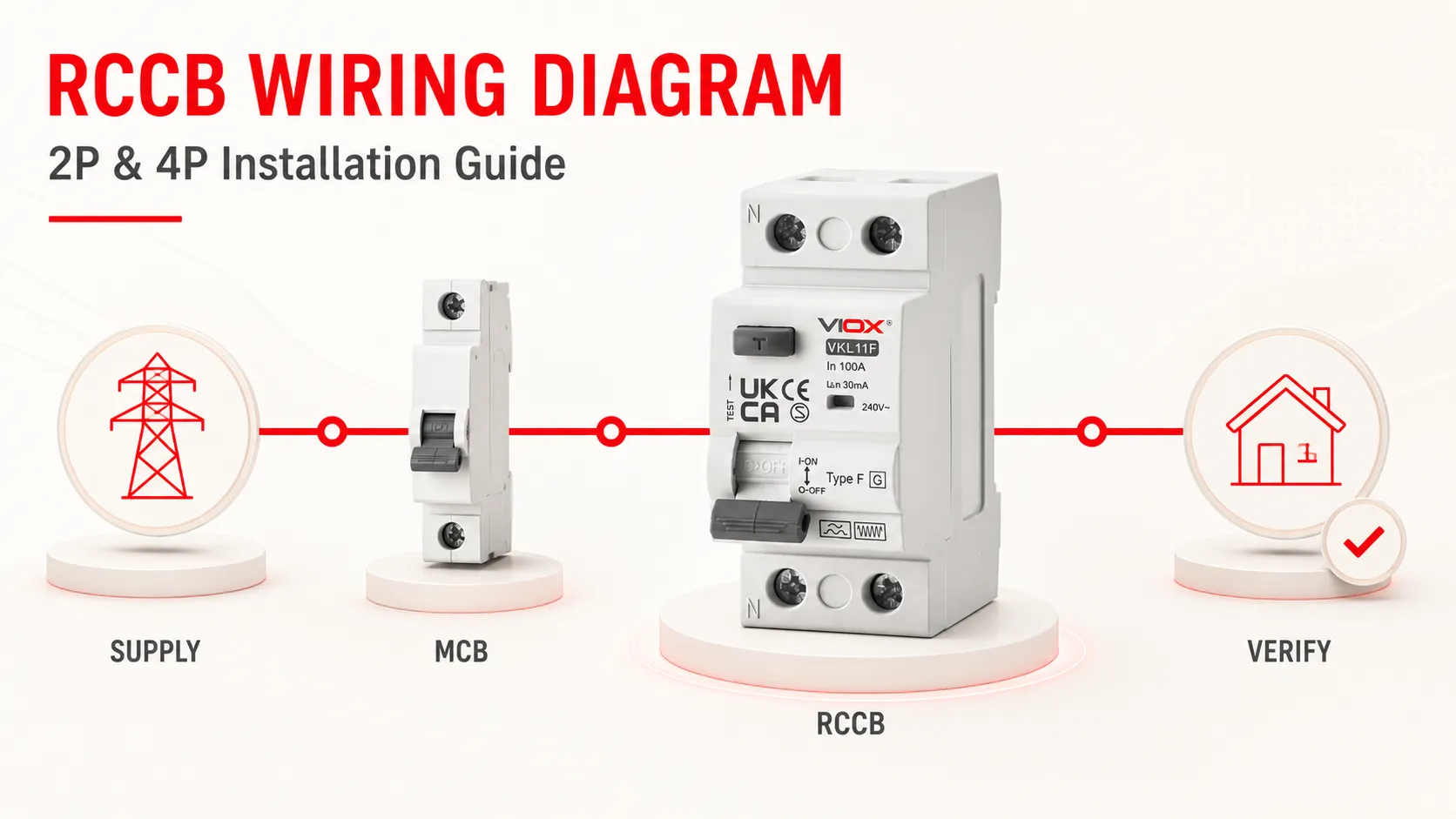
RCCB کو درست طریقے سے وائر کرنے کے لیے، محفوظ شدہ سرکٹ کو سپلائی کرنے والے ہر لائیو کنڈکٹر کو اسی RCCB سے گزاریں. ۔ سنگل فیز سرکٹ میں، اس کا عام طور پر مطلب لائن اور نیوٹرل کو 2-پول RCCB سے گزارنا ہے۔ تھری فیز، فور وائر سرکٹ میں، اس کا مطلب L1، L2، L3 اور نیوٹرل کو 4-پول RCCB سے گزارنا ہے۔ پروٹیکٹو ارتھ (PE) کنڈکٹر براہ راست PE بار سے منسلک ہوتا ہے؛ یہ RCCB کے پول سے نہیں گزرتا۔.
RCCB کو ایک الگ اوور کرنٹ پروٹیکٹو ڈیوائس کے ساتھ مربوط ہونا چاہیے کیونکہ یہ خود اوورلوڈ یا شارٹ سرکٹ سے تحفظ فراہم نہیں کرتا۔ تنصیب کے بعد، وائرنگ اور حفاظتی اقدامات کا معائنہ اور ٹیسٹ قابل اطلاق مقامی قوانین کے تحت کیا جانا چاہیے۔ صرف سامنے والا ٹیسٹ بٹن مکمل تصدیق نہیں ہے۔.
حفاظت اور دائرہ کار: فکسڈ ڈسٹری بیوشن بورڈ پر کام کرنے سے اہلکار بجلی کے جھٹکے، آرک فلیش، بیک فیڈ، اور ہائی فالٹ انرجی کا شکار ہو سکتے ہیں۔ RCCB کی تنصیب اور لائیو تصدیق صرف ایک مستند الیکٹریکل پروفیشنل کو منظور شدہ محفوظ ورک سسٹم کے تحت کرنی چاہیے۔ نیچے دیے گئے ڈایاگرام کنکشن کے اصولوں کی وضاحت کرتے ہیں؛ اصل RCCB پر چھپا ہوا ڈایاگرام، اس کی تنصیب کی ہدایات، پینل بنانے والے کی ضروریات، اور مقامی ضوابط کو فوقیت حاصل ہے۔.
RCCB کی وائرنگ ایک نظر میں
| سرکٹ | عام RCCB | RCCB میں سے گزرنے والے کنڈکٹرز | RCCB کے باہر کنڈکٹر | علیحدہ تحفظ درکار ہے |
|---|---|---|---|---|
| سنگل فیز، لائن + نیوٹرل | 2-پول آر سی سی بی | L اور N | پی ای (PE) | ڈیزائن کے مطابق MCB، MCCB، یا فیوز |
| تھری فیز، 4-وائر | 4-پول آر سی سی بی | L1، L2، L3، اور N | پی ای (PE) | ڈیزائن کے مطابق MCB، MCCB، یا فیوز |
| تھری فیز، 3 وائر | پروڈکٹ سے متعلق | مینوفیکچرر کی منظور شدہ ترتیب کا استعمال کرتے ہوئے تینوں فیزز | پی ای (PE) | ڈیزائن کے مطابق MCB، MCCB، یا فیوز |
ڈیوائس کے اوپری حصے سے سپلائی سائیڈ کا اندازہ نہ لگائیں۔ کچھ RCCBs لائن اور لوڈ کی سمت متعین کرتے ہیں؛ جبکہ کچھ ایک سے زیادہ ترتیب کی اجازت دیتے ہیں۔ اندرونی ٹیسٹ سرکٹ کا انحصار بھی مخصوص ٹرمینلز پر ہو سکتا ہے۔ ہمیشہ درست کیٹلاگ نمبر کے لیے نشانات اور ہدایات پر عمل کریں۔.
اگر آپ کو پہلے ڈیوائس کی بنیادی معلومات درکار ہیں، تو پڑھیں آر سی سی بی کیا ہے؟. اس گائیڈ کا باقی حصہ وائرنگ اور تنصیب کی تصدیق پر مرکوز ہے۔.
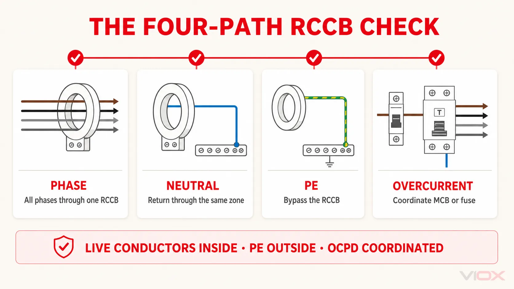
فور-پاتھ RCCB وائرنگ چیک
RCCB ڈایاگرام کی تصدیق کرنا آسان ہوتا ہے جب اسے چار کرنٹ راستوں میں تقسیم کیا جائے۔.
1. فیز پاتھ
ہر وہ فیز جو محفوظ لوڈ کو سپلائی فراہم کرتا ہے، اسے اسی RCCB کے سینسنگ سسٹم سے ایک بار گزرنا چاہیے۔ جو فیز RCCB کو بائی پاس کرتا ہے وہ مطلوبہ پیمائش کو ناکام بنا دیتا ہے؛ غلط طریقے سے سینسنگ پاتھ سے گزارا گیا کنڈکٹر بھی غیر ضروری ٹرپنگ کا باعث بن سکتا ہے۔.
نیوٹرل پاتھ
جہاں نیوٹرل استعمال ہوتا ہے، وہاں محفوظ سرکٹ سے منسلک نیوٹرل کو درست RCCB سے گزرنا چاہیے اور صرف اسی RCCB کے ڈاؤن اسٹریم نیوٹرل زون سے واپس آنا چاہیے۔ مشترکہ نیوٹرل، مستعار نیوٹرل، یا غلط نیوٹرل بار سے کنکشن عام لوڈ کرنٹ کو ریزیڈول کرنٹ کے طور پر ظاہر کر سکتا ہے۔.
پروٹیکٹو ارتھ پاتھ
PE لوڈ کے بے نقاب کنڈکٹیو حصوں کو انسٹالیشن کے پروٹیکٹو ارتھنگ سسٹم سے جوڑتا ہے۔ یہ مسلسل رہتا ہے اور RCCB کی سینسنگ اور سوئچنگ پاتھ سے باہر ہوتا ہے۔ PE کو سوئچ کرنے کے لیے کبھی بھی RCCB پول کا استعمال نہ کریں۔.
اوور کرنٹ پاتھ
ایک RCCB ریزیڈول کرنٹ کے عدم توازن کا پتہ لگاتا ہے۔ ایک مربوط MCB، MCCB، یا فیوز کو سرکٹ اور RCCB کو اوورلوڈ اور شارٹ سرکٹ کی صورتحال سے محفوظ رکھنا چاہیے۔ انتخاب کرتے وقت ڈیزائن کرنٹ، کنڈکٹر کی صلاحیت، ڈی ریٹنگ، متوقع فالٹ کرنٹ، اور مینوفیکچرر کے اعلان کردہ بیک اپ یا مشروط شارٹ سرکٹ کے انتظام کو مدنظر رکھنا چاہیے—صرف دو ایمپیئر مارکنگز کا موازنہ کافی نہیں ہے۔.
یہ چار راستے ایک فوری معائنہ کا اصول فراہم کرتے ہیں: ریزیڈول کرنٹ زون کے اندر تمام مطلوبہ لائیو کنڈکٹرز، اس کے باہر پی ای (PE)، اور مکمل سرکٹ میں اوور کرنٹ پروٹیکشن۔.
ڈسٹری بیوشن بورڈ میں آر سی سی بی (RCCB) کہاں لگایا جاتا ہے؟
گروپ پروٹیکشن کا ایک عام انتظام یہ ہے:
ان کمنگ سپلائیاس انتظام میں، آر سی سی بی (RCCB) ان برانچ ایم سی بیز (MCBs) سے پہلے ہوتا ہے جن کی یہ حفاظت کرتا ہے۔ تاہم، یہ کہنا کہ “آر سی سی بی کو ہر ایم سی بی سے پہلے ہونا چاہیے” بہت وسیع بات ہے۔ ایک پینل میں ہر فائنل سرکٹ کے لیے ایک آر سی بی او (RCBO)، اسپلٹ لوڈ کا انتظام، متعدد آر سی سی بی زونز، یا مختلف فزیکل ترتیب کے ساتھ ٹیسٹ شدہ اسمبلی کا استعمال کیا جا سکتا ہے۔.
ڈیزائن کا سوال صرف یہ نہیں ہے کہ ڈین ریل (DIN rail) پر کون سا آلہ پہلے آتا ہے۔ اس بات کی تصدیق کریں کہ:
- ریزیڈول کرنٹ پروٹیکشن مطلوبہ سرکٹ کا احاطہ کرتی ہے؛;
- اوور لوڈ اور شارٹ سرکٹ پروٹیکشن موجود اور مربوط ہے؛;
- ہر آر سی سی بی (RCCB) زون میں نیوٹرل کی روٹنگ درست ہے۔;
- حفاظتی امتزاج دستیاب فالٹ کرنٹ کے لیے موزوں ہے۔;
- جہاں سروس کا تسلسل اہم ہو، وہاں اپ اسٹریم اور ڈاؤن اسٹریم آر سی ڈی (RCD) سلیکٹیوٹی کا خیال رکھا گیا ہے۔
- اسمبلی اور بس بار کا انتظام استعمال شدہ آلات کے لیے منظور شدہ ہے۔.
آرکیٹیکچر کے فیصلے کے لیے، موازنہ کریں آر سی سی بی (RCCB) + ایم سی بی (MCB) بمقابلہ آر سی بی او (RCBO).
آر سی سی بی (RCCB) نصب کرنے سے پہلے کی جانچ پڑتال
عام کنکشن ڈایاگرام سے شروعات نہ کریں۔ پہلے اصل سرکٹ اور ڈیوائس کی شناخت کریں۔.
| چیک | وائرنگ سے پہلے تصدیق کریں | اس کی اہمیت |
|---|---|---|
| سپلائی | وولٹیج، فریکوئنسی، فیز کی تعداد، نیوٹرل کی دستیابی، ارتھنگ کا انتظام، اور تمام ممکنہ ذرائع | پول کے استعمال اور محفوظ آئسولیشن کے دائرہ کار کا تعین کرتا ہے |
| آر سی سی بی (RCCB) کی شناخت | کیٹلاگ نمبر، 2P/4P، ریٹیڈ کرنٹ میں, ریٹیڈ ریزیڈول آپریٹنگ کرنٹ IΔn, ٹائپ AC/A/F/B، اور ٹائم ڈیلے کی خصوصیات |
غلط حفاظتی فنکشن کی تنصیب سے روکتا ہے |
| ٹرمینل ڈایاگرام | مخصوص سپلائی/لوڈ سائیڈ، نیوٹرل پول، فیڈ کی مجاز سمت، اور کوئی بھی منظور شدہ 3-وائر کنکشن | عمومی ٹرمینل نمبرز آفاقی نہیں ہوتے |
| کنڈکٹرز | میٹریل، کراس سیکشن، تیاری، ٹرمینل کی گنجائش، اور فیرول یا لگ (lug) کے تقاضے | کنٹرولز کنکشن کی وشوسنییتا اور ہیٹنگ |
| ٹارک | پروڈکٹ دستاویزات میں ٹائٹننگ کی درست قدر اور ٹول کی ضرورت | ضرورت سے کم یا زیادہ ٹائٹ کرنا دونوں ہی کنکشن کو نقصان پہنچا سکتے ہیں |
| اوور کرنٹ کوآرڈینیشن | اپ اسٹریم او سی پی ڈی (OCPD)، ڈیزائن کرنٹ، متوقع فالٹ کرنٹ، اور ڈکلیئرڈ بیک اپ پروٹیکشن | آر سی سی بی (RCCB) میں اوور کرنٹ سے تحفظ کا کوئی مربوط نظام نہیں ہوتا |
| پینل سسٹم | ڈین ریل (DIN rail)، بس بار کی مطابقت، انکلوژر کی جگہ، حرارت کا اخراج، رکاوٹیں، اور مینوفیکچرر کی پابندیاں | یہ ڈیوائس ایک اسمبلی کا حصہ ہے، نہ کہ کوئی الگ تھلگ پرزہ |
| تصدیقی منصوبہ | درکار ڈیڈ ٹیسٹ، لائیو ٹیسٹ، آر سی ڈی (RCD) ٹیسٹر کی صلاحیت، ریکارڈز، اور مقامی قبولیت کے معیارات | ٹیسٹنگ کا عمل نصب شدہ ڈیوائس اور متعلقہ دائرہ اختیار کے مطابق ہونا چاہیے |
لوڈ، تحفظ کے مقصد، متوقع لیکیج، مقامی قوانین، اور آلات کی ہدایات کے مطابق حساسیت اور ریزیڈول کرنٹ کی قسم کا انتخاب کریں۔ 30 ملی ایمپیئر (mA) کی مارکنگ کا مطلب ریٹیڈ ریزیڈول آپریٹنگ کرنٹ 0.03 ایمپیئر ہے؛ اس کا یہ مطلب نہیں کہ 30 ملی ایمپیئر آر سی سی بی کی نارمل لوڈ کرنٹ ریٹنگ ہے۔ ملاحظہ کریں آر سی سی بی (RCCB) حساسیت کے انتخاب کی گائیڈ اس فیصلے کے لیے۔.
آر سی سی بی (RCCB) کی وائرنگ سے پہلے محفوظ آئسولیشن
اہل شخص کو سائٹ کے منظور شدہ آئسولیشن کے طریقہ کار اور قابل اطلاق قومی قواعد کی پیروی کرنی چاہیے، اور کام کے ایک محفوظ نظام کا استعمال کرنا چاہیے جیسا کہ درج ذیل اصولوں میں بیان کیا گیا ہے: ایچ ایس ای ایچ ایس جی 85 (HSE HSG85). کم از کم، منصوبہ میں یوٹیلیٹی سپلائی اور کسی بھی جنریٹر، یو پی ایس، فوٹو وولٹک سسٹم، کنٹرول ٹرانسفارمر، کپلڈ سرکٹ، یا کسی بھی ممکنہ بیک فیڈ کو مدنظر رکھنا ضروری ہے۔.
کام کرنے کا ایک عام محفوظ طریقہ کار یہ ہے:
- درست سرکٹ، آلات، اور ہر ذریعہ کی نشاندہی کریں؛;
- جہاں ضرورت ہو لوڈز کو بند کریں؛;
- مناسب آلات کا استعمال کرتے ہوئے سپلائی کو منقطع کریں۔;
- آئسولیشن کو دوبارہ جڑنے سے محفوظ بنائیں اور مطلوبہ انتباہی نوٹس لگائیں۔;
- وولٹیج ڈیٹیکشن آلے (voltage-detection instrument) کو چیک کر کے اس کی درستگی ثابت کریں۔;
- کام کرنے کی جگہ پر تمام متعلقہ کنڈکٹرز میں وولٹیج کی عدم موجودگی کی تصدیق کریں۔
- آلے کو دوبارہ چیک کر کے اس کی درستگی ثابت کریں۔.
ہینڈل کی پوزیشن، انڈیکیٹر لیمپ، نان کانٹیکٹ “وولٹ اسٹک” یا خود RCCB پر اس ثبوت کے طور پر انحصار نہ کریں کہ کنڈکٹرز ڈیڈ (بجلی سے پاک) ہیں۔ جہاں ملحقہ آلات میں بجلی موجود ہو، وہاں اضافی رکاوٹوں اور احتیاطی تدابیر کی ضرورت ہو سکتی ہے۔ اگر کام کو ڈیڈ حالت میں انجام نہیں دیا جا سکتا، تو اس کے لیے ایک الگ اور جائز لائیو ورک اسیسمنٹ اور طریقہ کار درکار ہوتا ہے؛ یہ مضمون ایسا کوئی طریقہ کار فراہم نہیں کرتا۔.
سنگل فیز سرکٹس کے لیے 2-پول RCCB وائرنگ ڈایاگرام
درج ذیل سنگل سرکٹ کا انتظام 2P RCCB سے پہلے لائن پاتھ میں 1P MCB کا استعمال کرتا ہے۔ یہاں، MCB ایک فائنل سرکٹ کے لیے اپ اسٹریم اوور کرنٹ پروٹیکٹو ڈیوائس ہے؛ یہ اوپر بیان کردہ گروپ ارینجمنٹ سے مختلف ہے، جہاں ایک RCCB کئی ڈاؤن اسٹریم برانچ MCBs کو سپلائی فراہم کرتا ہے۔ MCB ڈیزائن کردہ اوور کرنٹ تحفظ فراہم کرتا ہے، لائن اور نیوٹرل دونوں RCCB سے گزرتے ہیں، اور PE دونوں آلات کو بائی پاس کرتا ہے۔.
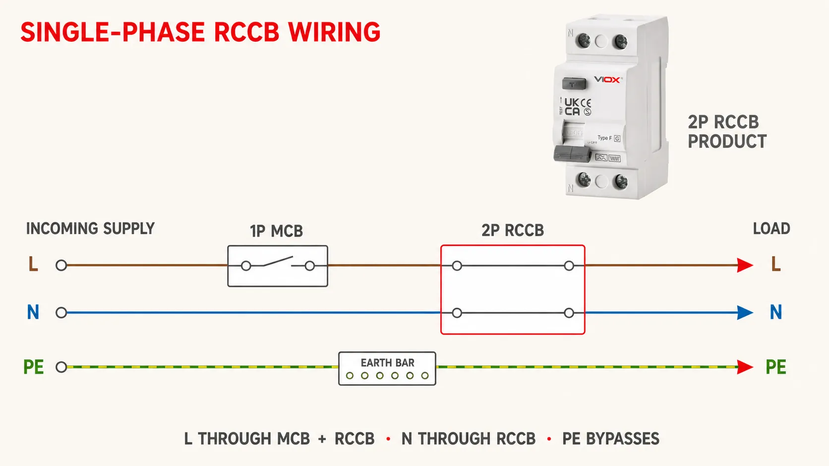
یہ خاکہ کرنٹ کے راستوں کو ظاہر کرتا ہے، نہ کہ یونیورسل ٹرمینل کے مقامات کو:
2-پول آر سی سی بی (RCCB).سنگل فیز کنکشن کی ترتیب
- متعلقہ RCCB پر مخصوص سپلائی اور لوڈ ٹرمینلز اور منظور شدہ حفاظتی ڈیوائس کی ترتیب کی تصدیق کریں۔.
- سورس لائن کو 1P MCB کے ذریعے گزار کر RCCB کے مخصوص سپلائی لائن ٹرمینل سے جوڑیں۔.
- سورس نیوٹرل کو براہ راست RCCB کے مخصوص سپلائی نیوٹرل ٹرمینل سے جوڑیں۔.
- منظور شدہ سرکٹ ڈیزائن کے مطابق، RCCB کے لوڈ سائیڈ لائن ٹرمینل کو محفوظ لوڈ یا ڈاؤن اسٹریم برانچ ڈیوائس سے جوڑیں۔.
- ڈاؤن اسٹریم نیوٹرل کو اس RCCB زون کے لیے مختص نیوٹرل بار سے جوڑیں۔.
- ہر محفوظ سرکٹ کے نیوٹرل کو صرف اسی مخصوص بار (bar) سے منسلک کریں۔.
- پی ای (PE) کنڈکٹرز کو آر سی سی بی (RCCB) پولز سے باہر، پی ای بار سے منسلک کریں۔.
- کنڈکٹر کی سیٹنگ، انسولیشن کلیئرنس، لیبلز، بیریئرز اور ٹرمینل کی سختی کا پروڈکٹ کی ہدایات کے مطابق معائنہ کریں۔.
آر سی سی بی (RCCB) اور برانچ ایم سی بیز (MCBs) کی جسمانی ترتیب منظور شدہ بورڈ ڈیزائن کے مطابق ہونی چاہیے۔ کومب بس بارز، فورک ٹرمینلز، یا ایک کیج میں دو کنڈکٹرز کا استعمال اپنی مرضی سے نہ کریں، جب تک کہ ٹرمینل اور اسمبلی کی دستاویزات اس کی اجازت نہ دیں۔.
تھری فیز سرکٹس کے لیے 4-پول آر سی سی بی (RCCB) وائرنگ ڈایاگرام
نیوٹرل استعمال کرنے والے تھری فیز لوڈ کے لیے، چاروں لائیو کنڈکٹرز عام طور پر ایک 4-پول آر سی سی بی (RCCB) سے گزرتے ہیں:
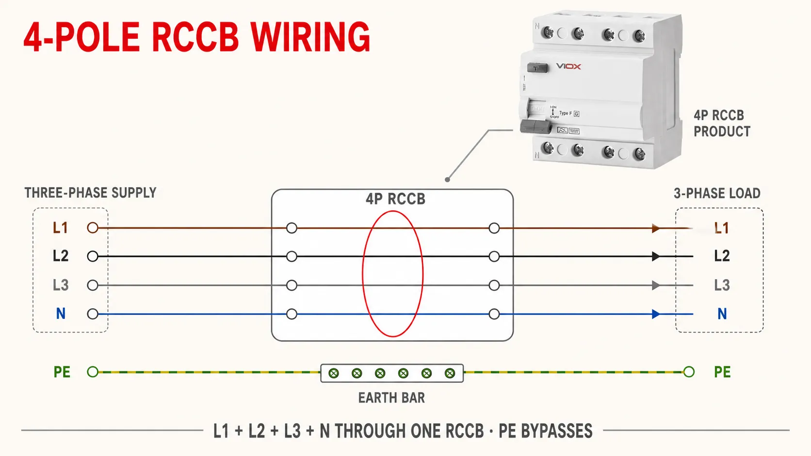
4-پول آر سی سی بی (RCCB) ڈاؤن اسٹریم.کنڈکٹر کی شناخت کو برقرار رکھیں اور نشان زدہ نیوٹرل پول کا استعمال کریں۔ اگر لوڈ یا متعلقہ آلات فیز روٹیشن پر منحصر ہیں، تو منظور شدہ کمیشننگ کے طریقہ کار کا استعمال کرتے ہوئے فیز سیکونس کی تصدیق کریں۔.
اگر تھری فیز سرکٹ میں نیوٹرل نہ ہو تو کیا ہوگا؟
کسی عام تھری وائر ڈایاگرام کو 4-پول آر سی سی بی (RCCB) پر کاپی نہ کریں۔ کچھ آلات بغیر نیوٹرل کے دستاویزی 3P کنکشن کی اجازت دیتے ہیں کیونکہ ان کا ٹیسٹ سرکٹ فیزز کے درمیان سپلائی کیا جاتا ہے۔ دیگر ڈیزائنز کو درست کام کرنے کے لیے مخصوص پول ارینجمنٹ، برج، معاون سپلائی یا نیوٹرل کی ضرورت ہوتی ہے۔ ایسا کنکشن جو لوڈ کو کامیابی سے اٹھا لے، وہ اندرونی ٹیسٹ یا الیکٹرانک ڈیٹیکشن فنکشن کو غلط طریقے سے سپلائی کر سکتا ہے۔.
صرف وہی نو-نیوٹرل ارینجمنٹ استعمال کریں جو خاص طور پر اس آر سی سی بی کے لیے شائع کی گئی ہو۔ مثال کے طور پر، شنائیڈر الیکٹرک (Schneider Electric) شائع کرتا ہے بغیر نیوٹرل کے تھری فیز سسٹم کے لیے ماڈل کے لحاظ سے مخصوص 4-پول آر سی سی بی کنکشن; ؛ اس ارینجمنٹ کو دوسرے آلات پر عام نہیں کیا جانا چاہیے۔ اگر ہدایات میں ایسا کوئی طریقہ نہ دکھایا گیا ہو، تو مینوفیکچرر سے تصدیق حاصل کریں یا خود سے تجربہ کرنے کے بجائے مناسب آلہ منتخب کریں۔.
ڈسٹری بیوشن بورڈ میں آر سی سی بی کو کیسے انسٹال کریں
ایک بار سرکٹ ڈیزائن اور محفوظ آئسولیشن قائم ہو جانے کے بعد، فزیکل تنصیب ایک کنٹرول شدہ ترتیب کے ساتھ کی جاتی ہے۔.
1. ڈیزائن کے مطابق آلے کی تصدیق کریں۔
پول کی تعداد، ریٹیڈ وولٹیج اور فریکوئنسی چیک کریں۔, میں, IΔn, ریزیڈول کرنٹ کی قسم، سلیکٹیو یا فوری ایکشن کا رویہ، ماحولیاتی حدود، اور پروڈکٹ اسٹینڈرڈ کو چیک کریں۔ تصدیق کریں کہ یہ آئٹم RCBO کے بجائے RCCB ہے۔.
2. RCCB کو ماؤنٹ کریں
ڈیوائس کو مطلوبہ سمت میں مخصوص DIN ریل یا پینل سسٹم پر فٹ کریں۔ کلیئرنس، وینٹیلیشن، بس بار کی سیدھ، ٹرمینل تک رسائی، اور ملحقہ آلات اور لوازمات کے ساتھ مطابقت کی تصدیق کریں۔.
3. کنڈکٹرز کو تیار کریں
مینوفیکچرر کی طرف سے منظور شدہ کنڈکٹر میٹریل، سائز، سٹرپ کی لمبائی، فیرولز اور لگز کا استعمال کریں۔ ٹرمینل کے لیے صرف اتنی انسولیشن ہٹائیں جتنی ضروری ہو۔ تاروں کے ریشوں کو بکھرنے سے روکیں اور انسولیشن کو کرنٹ لے جانے والے کلیمپ کے اندر نہ ڈالیں۔.
4. مانیٹر کیے جانے والے کنڈکٹرز کو جوڑیں
ہر فیز اور متعلقہ نیوٹرل کو دستاویزی سپلائی سے لوڈ کی سمت میں تفویض کردہ RCCB پولز کے ذریعے گزاریں۔ ہر RCD زون کے کنڈکٹرز کی شناخت برقرار رکھیں۔ RCCB پولز کو متوازی نہ کریں اور نہ ہی فالتو پولز کو کسی خود ساختہ طریقے سے استعمال کریں۔.
نیوٹرل اور پی ای (PE) کو درست طریقے سے ٹرمینیٹ کریں
ڈاؤن اسٹریم نیوٹرل کو اس کے مخصوص نیوٹرل بار یا لوڈ ٹرمینل سے جوڑیں۔ پی ای (PE) کو براہ راست پی ای بار سے جوڑیں۔ اس بات کو یقینی بنائیں کہ ڈاؤن اسٹریم میں نیوٹرل ٹو ارتھ لنک، مشترکہ نیوٹرل، یا آر سی ڈی (RCD) زونز کے درمیان کوئی کراس کنکشن موجود نہ ہو۔.
دستاویز کردہ ٹارک کے مطابق ٹائٹ کریں
پروڈکٹ کے لیے بیان کردہ ٹارک اور مناسب ٹول کا استعمال کریں۔ آر سی سی بی (RCCB) کے لیے کوئی محفوظ عالمی ٹارک ویلیو نہیں ہے۔ ٹائٹ کرنے کے بعد، ٹرمینیشن کو متاثر کیے بغیر مخصوص پل (pull) یا بصری معائنہ کریں۔.
رکاوٹوں اور لیبلز کو بحال کریں
ٹرمینل شروڈز، ڈیڈ فرنٹ، بلینکس اور کورز کو دوبارہ انسٹال کریں۔ انسٹالیشن کے قواعد کے مطابق محفوظ شدہ سرکٹس، آر سی سی بی زون، ٹیسٹ فنکشن، اور آئسولیٹنگ پوائنٹ پر لیبل لگائیں۔.
نیوٹرل اور ارتھ کے اصول جو زیادہ تر آر سی سی بی مسائل کو روکتے ہیں
| اصول | درست ترتیب | نظر انداز کرنے پر کیا خرابی پیدا ہوتی ہے |
|---|---|---|
| ہر آر سی سی بی (RCCB) کے نیوٹرل کو اسی آر سی سی بی کے ڈاؤن اسٹریم (آؤٹ پٹ سائیڈ) پر رکھیں | محفوظ شدہ سرکٹس کا نیوٹرل واپس اسی مخصوص نیوٹرل بار سے منسلک ہونا چاہیے | نارمل ریٹرن کرنٹ سینسر کو بائی پاس کر دیتا ہے اور ٹرپنگ کا باعث بنتا ہے |
| کبھی بھی کسی دوسرے سرکٹ سے نیوٹرل مستعار نہ لیں | فیز (لائن) اور اس سے منسلک نیوٹرل کو ایک ہی ریزیڈول کرنٹ زون میں رہنا چاہیے | لوڈ کرنٹ کسی بھی آر سی سی بی کے اندر متوازن نہیں رہتا |
| پی ای (PE) کو تمام کرنٹ لے جانے والے پولز سے باہر رکھیں | PE براہ راست حفاظتی ارتھنگ سسٹم سے گزرتا ہے۔ | PE کو سوئچ یا منقطع کرنے سے ایک اہم حفاظتی راستہ ختم ہو سکتا ہے۔ |
| ڈاؤن اسٹریم میں N-PE لنک شامل نہ کریں۔ | سسٹم ڈیزائن کے مطابق نیوٹرل اور PE الگ الگ رہتے ہیں۔ | نیوٹرل کرنٹ PE میں تقسیم ہو کر ریزیڈول عدم توازن پیدا کر سکتا ہے۔ |
| ہر لائیو کنڈکٹر کو ایک ہی RCCB سے گزاریں۔ | L/N یا L1/L2/L3/N کی نگرانی ایک ساتھ کی جاتی ہے۔ | بائی پاس شدہ کنڈکٹر کرنٹ کے مجموعی حساب (summation) کو ناکام بنا دیتا ہے۔ |
جہاں PEN کنڈکٹر موجود ہو، اسے نیوٹرل کنڈکٹر کے طور پر RCCB کے ذریعے روٹ یا سوئچ نہ کریں۔ RCCB کو سسٹم کے صرف اس حصے میں نصب کیا جانا چاہیے جہاں نیوٹرل اور PE کو لاگو تنصیبی اصولوں کے مطابق الگ کر دیا گیا ہو۔.
RCCB کا آپریشن PE سے گزرنے والے نارمل لوڈ کرنٹ پر منحصر نہیں ہوتا؛ یہ مانیٹر کیے گئے لائیو کنڈکٹرز کے درمیان عدم توازن کی پیمائش کرتا ہے۔ یہ ضروری نہیں حفاظتی ارتھنگ (protective earthing) کی ضرورت کو ختم نہیں کرتا۔ RCCB پروٹیکشن اور حفاظتی ارتھنگ مختلف افعال انجام دیتے ہیں، اور دونوں کو انسٹالیشن ڈیزائن کے مطابق ہونا چاہیے۔.
RCCB + MCB یا RCBO؟
دونوں آرکیٹیکچرز ریزیڈول کرنٹ اور اوور کرنٹ سے تحفظ فراہم کر سکتے ہیں، لیکن وہ خطرے اور جگہ کو مختلف طریقے سے تقسیم کرتے ہیں۔.
| فن تعمیر | عملی فائدہ | بنیادی تجارتی سمجھوتہ (Trade-off) |
|---|---|---|
| ایک RCCB جو کئی MCBs کو فیڈ کرتا ہے | ریزیڈول کرنٹ ڈیوائسز کی کم تعداد اور ممکنہ طور پر اجزاء کی کم قیمت | ایک ریزیڈول فالٹ کئی سرکٹس کو منقطع کر سکتا ہے؛ نیوٹرل کی علیحدگی انتہائی اہم ہے۔ |
| ہر فائنل سرکٹ کے لیے ایک RCBO کا استعمال۔ | فالٹ آئسولیشن عام طور پر ایک سرکٹ تک محدود ہوتی ہے؛ نیوٹرل کی ملکیت کا تعین آسان ہوتا ہے۔ | زیادہ ڈیوائسز اور ممکنہ طور پر پینل میں زیادہ جگہ یا زیادہ لاگت۔ |
مقامی قوانین، تسلسل کی ضروریات، لیکیج کرنٹ کا تخمینہ، سلیکٹیوٹی پلان، اور بورڈ ڈیزائن کے مطابق درکار آرکیٹیکچر استعمال کریں۔ صرف ٹرپنگ بڑھا کر نیوسینس ٹرپنگ (nuisance tripping) کا حل نہ نکالیں۔ IΔn; پہلے سرکٹ لیکیج، لوڈ کی خصوصیات، وائرنگ کی غلطیوں، اور تحفظ کے مقصد کی نشاندہی کریں۔.
تنصیب کے بعد کمیشننگ اور تصدیق۔
تنصیب کی تصدیق صرف RCCB کو آن کرنے سے زیادہ ہے۔ درست ترتیب اور حدود کا انحصار قابل اطلاق قومی قوانین، پروجیکٹ دستاویزات، آلات کی ہدایات، اور ٹیسٹر کی اہلیت پر ہوتا ہے۔. IEC 60364-6 کم وولٹیج کی برقی تنصیبات کی ابتدائی اور وقتاً فوقتاً تصدیق کے لیے بین الاقوامی فریم ورک فراہم کرتا ہے۔.
بصری اور ڈیڈ چیکس (بغیر بجلی کے معائنہ)
بجلی بحال کرنے سے پہلے، تصدیق کریں:
- درست RCCB کی قسم اور ریٹنگز نصب کی گئی ہیں؛;
- کنڈکٹرز سرکٹ شیڈول اور ٹرمینل ڈایاگرام کے مطابق ہیں؛;
- محفوظ سرکٹ کے تمام لائیو کنڈکٹرز درست RCCB سے گزرتے ہیں؛;
- ڈاؤن اسٹریم نیوٹرل بار صرف اسی RCCB زون سے تعلق رکھتی ہے؛;
- سسٹم کے لیے PE تسلسل (continuity) اور N-PE علیحدگی درست ہے؛;
- ٹرمینلز دستاویزی ٹارک پر محفوظ طریقے سے کسے ہوئے ہیں؛;
- اوور کرنٹ اور شارٹ سرکٹ کوآرڈینیشن ڈیزائن کے مطابق ہے؛ اور
- کور، بیریئرز، لیبلز، اور انکلوژر پروٹیکشن کو بحال کر دیا گیا ہے۔.
منسلک الیکٹرانک آلات کے لیے موزوں طریقہ کار کا استعمال کرتے ہوئے مطلوبہ تسلسل، انسولیشن ریزسٹنس، پولرٹی، اور دیگر ڈیڈ ٹیسٹ مکمل کریں۔.
فنکشنل ٹیسٹ بٹن چیک
منظور شدہ طریقہ کار کے تحت تنصیب کو محفوظ طریقے سے بجلی فراہم کرنے کے بعد، مینوفیکچرر کی بیان کردہ شرائط کے تحت RCCB کا ٹیسٹ بٹن چلائیں۔ RCCB کو ٹرپ ہونا چاہیے اور مطلوبہ کنڈکٹرز کو منقطع کرنا چاہیے۔.
یہ بٹن اندرونی آپریٹنگ پاتھ اور ٹرپنگ میکانزم کو چیک کرتا ہے۔ یہ حفاظتی کنڈکٹر کے تسلسل، انسولیشن ریزسٹنس، درست پولرٹی، مکسڈ نیوٹرلز کی عدم موجودگی، یا مکمل تنصیب کی پیمائش شدہ ٹرپ کارکردگی کو ثابت نہیں کرتا ہے۔ بٹن ٹیسٹ میں ناکامی غلط سپلائی وولٹیج یا پروڈکٹ کے مخصوص غلط کنکشن کی وجہ سے بھی ہو سکتی ہے، لہذا ڈیوائس کو بار بار چلانے کے بجائے بجلی منقطع کریں اور جانچ پڑتال کریں۔.
آلات کی تصدیق
جہاں ضروری ہو، ایک اہل شخص کو چاہیے کہ وہ مناسب آر سی ڈی (RCD) ٹیسٹ آلات اور مقامی تصدیقی طریقہ کار کا استعمال کرتے ہوئے نصب شدہ حفاظتی اقدامات کی افادیت کی تصدیق کرے۔ ٹیسٹر، ویوفارم سیٹنگ، ٹیسٹ پوائنٹ، منسلک لوڈز، اور قبولیت کے معیارات کا آر سی سی بی (RCCB) کی قسم اور متعلقہ دائرہ اختیار کے مطابق ہونا ضروری ہے۔. آئی ای سی 61557-6 (IEC 61557-6) یہ معیار نصب شدہ سسٹمز میں آر سی ڈی (RCD) کی افادیت کو جانچنے کے لیے استعمال ہونے والے پیمائشی آلات کا احاطہ کرتا ہے؛ یہ قابل اطلاق وائرنگ کے قواعد کی جگہ نہیں لیتا۔.
ڈیوائس کی شناخت، سرکٹ،, IΔn, ، ٹیسٹ کے حالات، نتائج، تاریخ، اور ٹیسٹر کا ریکارڈ رکھیں۔ اگر آر سی سی بی (RCCB) یا تنصیب مطلوبہ جانچ میں ناکام ہو جائے، تو متاثرہ سرکٹ کو اس وقت تک سروس سے باہر رکھیں جب تک کہ خرابی کو دور نہ کر لیا جائے اور تصدیق دوبارہ نہ کر لی جائے۔.
وقتاً فوقتاً جانچ اور گہرائی سے فالٹ تشخیص کے لیے، الگ سے استعمال کریں آر سی سی بی (RCCB) ٹیسٹنگ اور مینٹیننس گائیڈ.
آر سی سی بی (RCCB) کی وائرنگ میں عام غلطیاں
| غلطی | RCCB کیا پتہ لگاتا ہے | اصلاحی سمت |
|---|---|---|
| ڈائریکشنل ڈیوائس کو غلط سائیڈ سے سپلائی دینا | ٹیسٹ فنکشن کا کام نہ کرنا یا تحفظ کا ڈیزائن کے مطابق عمل نہ کرنا | لائن/لوڈ کے درست ڈایاگرام کی پیروی کریں |
| نیوٹرل کا آر سی سی بی (RCCB) کو بائی پاس کرنا | فوری یا لوڈ پر منحصر ٹرپنگ؛ نامکمل تحفظ | متعلقہ نیوٹرل کو درست پول اور نیوٹرل زون سے گزاریں |
| دو آر سی سی بی (RCCBs) کے درمیان نیوٹرلز کا آپس میں مل جانا | جب لوڈ چلتے ہیں تو ایک یا دونوں ڈیوائسز ٹرپ کر جاتی ہیں | ڈاؤن اسٹریم نیوٹرل بارز اور سرکٹس کو الگ کریں اور ان کی شناخت کریں |
| ڈاؤن اسٹریم این-پی ای (N-PE) کنکشن | نارمل نیوٹرل کرنٹ کا کچھ حصہ پی ای (PE) کے ذریعے واپس آتا ہے | منظور شدہ طریقہ کار کے تحت غیر ارادی لنک کو تلاش کریں اور ہٹائیں |
| پی ای (PE) کو ایک پول کے ذریعے روٹ کیا گیا ہے | پروٹیکٹو ارتھ (PE) کا تسلسل منقطع یا سوئچ ہو سکتا ہے | پی ای (PE) کو براہ راست پی ای بار سے منسلک کریں |
| صرف کچھ فیز کنڈکٹرز 4P RCCB سے گزرتے ہیں | کرنٹ کا مجموعہ درست نہیں ہے | منظور شدہ ڈایاگرام کا استعمال کرتے ہوئے تمام لائیو کنڈکٹرز کو روٹ کریں |
| نیوٹرل کے بغیر عام 3P کنکشن استعمال کیا گیا ہے | اندرونی ٹیسٹ/الیکٹرانک سرکٹ کو غلط طریقے سے سپلائی دی گئی ہو سکتی ہے | ماڈل کے لیے مخصوص نو-نیوٹرل (no-neutral) ڈایاگرام استعمال کریں |
| کوئی مربوط OCPD موجود نہیں ہے | RCCB اور کنڈکٹرز میں اوورلوڈ/شارٹ سرکٹ سے تحفظ کا فقدان ہے | ڈیزائن کردہ MCB، MCCB، یا فیوز فراہم کریں اور فالٹ کرنٹ کوآرڈینیشن کی تصدیق کریں۔ |
| ٹرمینل ٹارک کا اندازہ لگانا۔ | ڈھیلا کنکشن، زیادہ گرمی، یا کنڈکٹر کو نقصان۔ | دستاویزی ٹارک اور مناسب اوزار استعمال کریں۔ |
| ٹیسٹ بٹن کو مکمل کمیشننگ سمجھنا۔ | وائرنگ یا حفاظتی اقدامات میں نقائص کا پتہ نہ چلنا۔ | مطلوبہ معائنہ اور آلات کے ٹیسٹ مکمل کریں۔ |
نیا نصب شدہ RCCB فوراً ٹرپ کیوں کر جاتا ہے؟
سب سے پہلے وائرنگ کے مسئلے کو حقیقی ریزیڈول کرنٹ فالٹ سے الگ کریں۔ عام وجوہات میں شامل ہیں:
- ڈاؤن اسٹریم نیوٹرل کا غلط نیوٹرل بار سے منسلک ہونا؛;
- سرکٹس کے درمیان مشترکہ نیوٹرل کا ہونا؛;
- ڈاؤن اسٹریم نیوٹرل ٹو ارتھ کنکشن؛;
- کوئی فیز یا نیوٹرل جو RCCB کو بائی پاس کر رہا ہو؛;
- موجودہ انسولیشن لیکیج یا کئی لوڈز جن کی مجموعی لیکیج جمع ہو رہی ہو؛;
- منسلک الیکٹرانک لوڈ کے لیے غیر موزوں RCCB کی قسم؛;
- تنصیب کے دوران پیدا ہونے والا نقصان؛ یا
- سرکٹس کی غلط کوآرڈینیشن یا گروپنگ۔.
وجہ کی نشاندہی کیے بغیر RCCB کو بار بار ری سیٹ نہ کریں۔ متاثرہ لوڈز کو الگ کریں اور دستاویزی ٹربل شوٹنگ کے طریقہ کار کے تحت تحقیق کریں۔ اصطلاحات کی گائیڈ ریزیڈول کرنٹ، لیکیج کرنٹ، اور گراؤنڈ کرنٹ شامل پیمائشوں میں فرق کرنے میں مدد کر سکتی ہے۔.
اکثر پوچھے گئے سوالات
کیا RCCB کو MCB سے پہلے نصب کیا جانا چاہیے یا بعد میں؟
عام گروپ کی ترتیب میں، RCCB برانچ MCBs کے اپ اسٹریم (اوپر) ہوتا ہے، جبکہ ایک اپ اسٹریم مین ڈیوائس بیک اپ اوور کرنٹ پروٹیکشن فراہم کر سکتی ہے۔ دیگر درست ڈیزائنز میں انفرادی RCBOs یا مختلف فزیکل ترتیب کے ساتھ ٹیسٹ شدہ اسمبلیاں استعمال ہوتی ہیں۔ کسی ایک عالمی ترتیب پر انحصار کرنے کے بجائے کوریج، نیوٹرل زوننگ، کرنٹ ریٹنگ، فالٹ کرنٹ کوآرڈینیشن، اور مینوفیکچرر کی ہدایات کی تصدیق کریں۔.
کیا RCCB کو اوپر یا نیچے سے سپلائی دی جا سکتی ہے؟
صرف تب، اگر مینوفیکچرر اس مخصوص ماڈل کے لیے اس کنکشن کی اجازت دیتا ہو۔ سپلائی کی سمت ٹرمینل کی شناخت، ٹیسٹ سرکٹ، یا وولٹیج پر منحصر الیکٹرانکس کو متاثر کر سکتی ہے۔ پرنٹ شدہ ڈایاگرام اور تنصیب کی ہدایات پر عمل کریں۔.
کیا نیوٹرل RCCB سے گزرتا ہے؟
جی ہاں، جہاں محفوظ سرکٹ نیوٹرل کا استعمال کرتا ہے، وہاں اس کا متعلقہ نیوٹرل عام طور پر RCCB کے مخصوص نیوٹرل پول سے گزرتا ہے۔ اسے پھر ڈاؤن اسٹریم نیوٹرل زون کے ذریعے واپس آنا چاہیے، نہ کہ کسی دوسرے سرکٹ کی نیوٹرل بار کے ذریعے۔.
کیا ارتھ وائر RCCB سے گزرتی ہے؟
نہیں۔ پروٹیکٹو ارتھ کنڈکٹر براہ راست PE بار اور کھلے کنڈکٹیو حصوں سے جڑتا ہے۔ یہ RCCB پول کے ذریعے سوئچ نہیں ہوتا۔ RCCB اس کرنٹ کا پتہ لگاتا ہے جو مطلوبہ لائیو کنڈکٹر کے راستے سے باہر نکل جاتا ہے، لیکن یہ ضروری پروٹیکٹو ارتھنگ کی جگہ نہیں لیتا۔.
2-پول اور 4-پول RCCB وائرنگ ڈایاگرام میں کیا فرق ہے؟
ایک عام 2-پول RCCB سنگل فیز سرکٹ میں لائن اور نیوٹرل کی نگرانی کرتا ہے۔ ایک عام 4-پول RCCB تھری فیز، فور وائر سرکٹ میں L1، L2، L3 اور نیوٹرل کی نگرانی کرتا ہے۔ نیوٹرل کے بغیر تھری فیز سسٹمز کے لیے مینوفیکچرر کی منظور شدہ پروڈکٹ کے مطابق کنکشن درکار ہوتا ہے۔.
کیا آر سی سی بی اوورلوڈ اور شارٹ سرکٹ سے تحفظ فراہم کرتا ہے؟
IEC 61008-1 کے مطابق RCCB ایک ریزیڈول کرنٹ ڈیوائس ہے جس میں انٹیگرل اوور کرنٹ پروٹیکشن نہیں ہوتی۔ لہذا مکمل سرکٹ کے لیے ایک مربوط MCB، MCCB، فیوز، یا مشترکہ RCBO حل کی ضرورت ہوتی ہے۔ مزید جانیں RCCB بمقابلہ MCB.
کیا تنصیب کے بعد ٹیسٹ بٹن دبانا کافی ہے؟
نہیں۔ یہ ایک اہم فنکشنل چیک ہے، لیکن یہ مکمل وائرنگ یا حفاظتی اقدامات کی تصدیق نہیں کرتا۔ ابتدائی تصدیق کے لیے بصری معائنے، ڈیڈ ٹیسٹ، اور قابل اطلاق تنصیبی قواعد کے تحت آلات کے ذریعے ٹیسٹنگ کی بھی ضرورت ہو سکتی ہے۔.
حتمی RCCB وائرنگ چیک لسٹ
سرکٹ کو سروس میں لانے سے پہلے، چار چیزوں کی تصدیق کریں: ہر فیز مطلوبہ RCCB راستے پر ہو، متعلقہ نیوٹرل اسی RCCB زون کے اندر رہے، PE ڈیوائس کے باہر مسلسل برقرار رہے، اور مربوط اوور کرنٹ پروٹیکشن موجود ہو۔. پھر پروڈکٹ کی ہدایات اور قابل اطلاق مقامی قواعد کا استعمال کرتے ہوئے تنصیب کی تصدیق کریں—صرف ٹیسٹ بٹن پر انحصار نہ کریں۔.
ایک بار جب مطلوبہ پول کی تعداد،, میں, IΔn, ، RCCB کی قسم، وولٹیج، اور کوآرڈینیشن کا تعین ہو جائے، تو جائزہ لیں VIOX آر سی سی بی (RCCB) رینج یا ماڈل سے متعلق مخصوص دستاویزات کے لیے VIOX سے رابطہ کریں۔.
تکنیکی حوالہ جات
- IEC 61008-1:2024 — RCCBs بغیر انٹیگرل اوور کرنٹ پروٹیکشن، حصہ 1: عمومی اصول
- IEC 60364-6:2016 — لو وولٹیج الیکٹریکل تنصیبات، حصہ 6: تصدیق
- IEC 61557-6:2019 — RCD حفاظتی اقدامات کی تاثیر کو جانچنے کے لیے آلات
- HSE HSG85 — کام کی جگہ پر بجلی: محفوظ کام کے طریقے
- ABB F200 125 A تنصیب کی ہدایات
- Schneider Electric — بغیر نیوٹرل کے 3-فیز پر 4-پول Acti9 iID RCCB کا استعمال
- Schneider Electric — ریزیڈول کرنٹ ڈیوائسز (RCDs) کی معمول کی آپریٹنگ چیکنگ