এই পৃষ্ঠায়
ক কারেন্ট মনিটরিং রিলে AC বা DC কারেন্ট পরিমাপ করে, এটিকে এক বা একাধিক থ্রেশহোল্ডের সাথে তুলনা করে, টাইমিং এবং রিসেট লজিক প্রয়োগ করে এবং মনিটর করা অবস্থা অস্বাভাবিক হলে একটি কন্ট্রোল আউটপুট পরিবর্তন করে। আউটপুটটি একটি কন্টাক্টরকে কমান্ড দিতে পারে, একটি PLC-কে জানাতে পারে বা একটি অ্যালার্ম পরিচালনা করতে পারে। বেশিরভাগ অ্যাপ্লিকেশনে, মনিটরিং রিলে নিজে থেকে লোড কারেন্ট বিচ্ছিন্ন করে না বা ফল্ট দূর করে না।.
এটি কারেন্ট মনিটরিংকে তখন কার্যকর করে তোলে যখন বৈদ্যুতিক লোড মেশিনের অবস্থার একটি ব্যবহারিক নির্দেশক হয়। কারেন্ট বৃদ্ধি জ্যাম বা অতিরিক্ত যান্ত্রিক লোডের ইঙ্গিত দিতে পারে। কারেন্ট হ্রাস ড্রাই রানিং, বেল্ট ছিঁড়ে যাওয়া, লোড হারানো বা হিটিং এলিমেন্ট খোলা থাকার ইঙ্গিত দিতে পারে। ইঞ্জিনিয়ারিংয়ের কাজ হলো কারেন্ট প্রক্রিয়ার জন্য একটি নির্ভরযোগ্য বিকল্প কি না তা নির্ধারণ করা, তারপর এমন থ্রেশহোল্ড এবং বিলম্ব সেট করা যা স্বাভাবিক অপারেটিং ট্রানজিয়েন্ট থেকে প্রকৃত ফল্টকে আলাদা করতে পারে।.
কারেন্ট মনিটরিং রিলে কী?
একটি কারেন্ট মনিটরিং রিলে—যাকে কারেন্ট সেন্সিং রিলে বা কারেন্ট রিলেও বলা হয়—হলো একটি পরিমাপ ও সিদ্ধান্ত গ্রহণকারী ডিভাইস যা কন্ট্রোল সার্কিটে ব্যবহৃত হয়। এর কাজকে পাঁচটি ধাপে ভাগ করা যায়:
- পরিমাপ: সরাসরি অথবা উপযুক্ত সেন্সরের মাধ্যমে লোড কারেন্ট শনাক্ত করা।.
- তুলনা: পরিমাপ করা মানটিকে একটি ওভারকারেন্ট থ্রেশহোল্ড, আন্ডারকারেন্ট থ্রেশহোল্ড অথবা উভয়ের সাথে পরীক্ষা করা।.
- সময়ের ভিত্তিতে যাচাই: অবস্থাটিকে একটি কনফিগার করা বিলম্ব পর্যন্ত বজায় রাখার প্রয়োজন হয়।.
- আউটপুট অবস্থা পরিবর্তন: একটি ইলেকট্রোমেকানিক্যাল বা সলিড-স্টেট কন্ট্রোল আউটপুট পরিচালনা করুন।.
- একটি বাহ্যিক প্রতিক্রিয়া শুরু করুন: একটি কন্টাক্টর, PLC, অ্যালার্ম বা অন্য কোনো কন্ট্রোল ডিভাইসকে প্রয়োজনীয় কাজটি সম্পাদন করতে দিন।.
এই সিগন্যাল চেইনটি হলো প্রধান পার্থক্য মনিটরিং এবং পাওয়ার ইন্টারাপশন. । একটি রিলে একটি স্টপ সিকোয়েন্স শুরু করতে পারে, তবে পাওয়ার সার্কিট সুইচ বা সুরক্ষা করার জন্য নির্বাচিত ডিভাইসটিকে সেই পৃথক কাজের জন্য রেট করা থাকতে হবে।.
কারেন্ট মনিটরিং রিলে কীভাবে কাজ করে
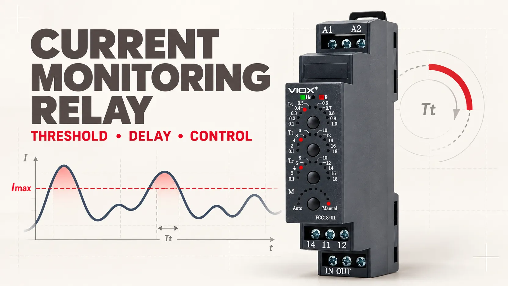
রিলেটি ক্রমাগত মনিটর করা কারেন্ট মূল্যায়ন করে, যা এখানে প্রদর্শিত হয়েছে আমি, একটি অ্যাডজাস্টেবল বা ফিক্সড রেফারেন্সের বিপরীতে।.
ওভারকারেন্ট মনিটরিং
একটি ওভারকারেন্ট মনিটরিং রিলে তার টাইমিং লজিক শুরু করে যখন আমি উচ্চ থ্রেশহোল্ডের উপরে উঠে যায় আইম্যাক্স. । যদি কারেন্ট ট্রিপ ডিলে-এর জন্য থ্রেশহোল্ডের উপরে থাকে, তবে আউটপুট তার অবস্থা পরিবর্তন করে। যদি ডিলে শেষ হওয়ার আগেই কারেন্ট অনুমোদিত সীমার মধ্যে ফিরে আসে, তবে সঠিকভাবে কনফিগার করা রিলে কোনো ফল্ট আউটপুট প্রদান করে না।.
এই ডিলে মোটর স্টার্টিং কারেন্ট, হিটার ইনরাশ, সংক্ষিপ্ত কাটিং পিক বা অন্যান্য প্রত্যাশিত ট্রানজিয়েন্টগুলোকে উপেক্ষা করতে পারে। এটি সঠিকভাবে সমন্বিত শর্ট সার্কিট বা অতিভার সুরক্ষার বিকল্প নয়।.
আন্ডারকারেন্ট মনিটরিং
একটি আন্ডারকারেন্ট রিলে তার টাইমিং লজিক শুরু করে যখন আমি নিম্ন সীমার নিচে নেমে যায় Imin. দীর্ঘস্থায়ী নিম্ন কারেন্ট নির্দেশ করতে পারে যে একটি মোটরের যান্ত্রিক লোড কমে গেছে, একটি পাম্প শুষ্ক অবস্থায় চলছে, একটি বেল্ট ছিঁড়ে গেছে, অথবা একটি হিটার শাখা খোলা রয়েছে। এর ব্যাখ্যা যন্ত্রের ওপর নির্ভর করে: নিম্ন কারেন্ট বৈদ্যুতিক লোড হ্রাসের প্রমাণ, কোনো নির্দিষ্ট যান্ত্রিক ত্রুটির নিশ্চিত প্রমাণ নয়।.
উইন্ডো মনিটরিং
একটি উইন্ডো কারেন্ট রিলে উভয় সীমা পর্যবেক্ষণ করে। কারেন্ট যতক্ষণ পর্যন্ত এর মধ্যে থাকে ততক্ষণ তা গ্রহণযোগ্য Imin এবং আইম্যাক্স. নিম্ন সীমার নিচে নেমে গেলে বা উচ্চ সীমার উপরে উঠে গেলে সংশ্লিষ্ট টাইমিং লজিক শুরু হয়। যখন লোড হারানো এবং অতিরিক্ত লোড উভয়ই গুরুত্বপূর্ণ ত্রুটিপূর্ণ অবস্থা হয়, তখন উইন্ডো মনিটরিং কার্যকর হয়।.
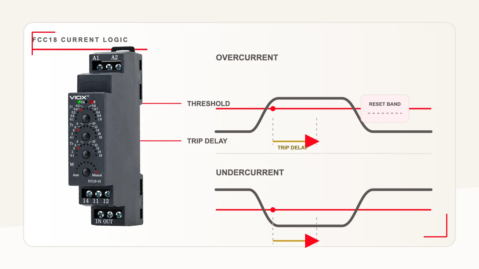
আউটপুট পরিবর্তনের আগে কারেন্টকে অবশ্যই কনফিগার করা বিলম্বের জন্য একটি থ্রেশহোল্ড অতিক্রম করতে হবে; রিসেট আচরণ মডেল-নির্দিষ্ট।.
রিসেট লেভেল এবং হিস্টেরেসিস কেন গুরুত্বপূর্ণ
যদি একটি রিলে ঠিক সেই মানটিতে ট্রিপ করে যেখানে এটি রিসেট হয়, তবে থ্রেশহোল্ডের কাছাকাছি ছোট কারেন্ট ওঠানামা আউটপুটকে চ্যাটারিং বা কাঁপাতে পারে। তাই নির্মাতারা পরিচালনা এবং রিলিজ অবস্থার মধ্যে একটি রিসেট সীমানা বা হিস্টেরেসিস নির্ধারণ করেন। কিছু মডেল এটিকে থ্রেশহোল্ডের শতাংশ হিসেবে প্রকাশ করে; অন্যরা আলাদা পিকআপ এবং ড্রপআউট মান প্রকাশ করে।.
কারেন্ট অনুমোদিত সীমার মধ্যে ফিরে আসার পর রিসেট স্বয়ংক্রিয় হতে পারে, অথবা ম্যানুয়াল হতে পারে যাতে একজন অপারেটরকে ঘটনাটি নিশ্চিত করতে হয়। একটি পৃথক রিসেট বিলম্বও উপলব্ধ থাকতে পারে। সর্বদা নির্বাচিত মডেলের টাইমিং ডায়াগ্রাম পড়ুন: একই রকম ফ্রন্ট-প্যানেল লেবেল ভিন্ন ভিন্ন আউটপুট সিকোয়েন্স তৈরি করতে পারে।.
কারেন্ট মনিটরিং রিলে কী করে—এবং কী করে না
একটি কারেন্ট মনিটর পরিমাপ এবং নিয়ন্ত্রণ স্তরের অন্তর্ভুক্ত। এটিকে প্যানেলের প্রতিটি কারেন্ট-সম্পর্কিত ডিভাইসের স্বয়ংক্রিয় বিকল্প হিসেবে গণ্য করা উচিত নয়।.
| যন্ত্র | প্রধান কাজ | এটি যা প্রদান করে | এটি যা স্বয়ংক্রিয়ভাবে প্রতিস্থাপন করে না |
|---|---|---|---|
| কারেন্ট মনিটরিং রিলে | কারেন্ট অবস্থা শনাক্ত করা এবং একটি কন্ট্রোল আউটপুট পরিবর্তন করা | থ্রেশহোল্ড, টাইমিং, রিসেট এবং সিগন্যালিং লজিক | ব্রাঞ্চ শর্ট সার্কিট সুরক্ষা বা একটি পাওয়ার সুইচিং ডিভাইস |
| কারেন্ট ট্রান্সফরমার (CT) | একটি স্কেলড সেকেন্ডারি মানে কারেন্ট পুনরুৎপাদন করা | সামঞ্জস্যপূর্ণ সরঞ্জামের জন্য গ্যালভানিক্যালি আইসোলেটেড কারেন্ট পরিমাপ ইন্টারফেস | একটি সম্পূর্ণ থ্রেশহোল্ড সিদ্ধান্ত এবং কন্ট্রোল আউটপুট |
| থার্মাল ওভারলোড রিলে | একটি থার্মাল মডেল অনুযায়ী দীর্ঘস্থায়ী মোটর অতিভারের প্রতি সাড়া প্রদান | নির্বাচিত ডিভাইস দ্বারা সংজ্ঞায়িত মোটর অতিভার এবং ফেজ-সম্পর্কিত সুরক্ষা ফাংশন | সাধারণ-উদ্দেশ্যমূলক প্রসেস আন্ডারকারেন্ট মনিটরিং |
| সার্কিট ব্রেকার বা ফিউজ | এর রেটিংয়ের মধ্যে নির্দিষ্ট ফল্ট কারেন্ট বিচ্ছিন্ন করা | ডিজাইন অনুযায়ী ওভারকারেন্ট সুরক্ষা এবং সার্কিট আইসোলেশন | প্রসেস-স্টেট ইন্টারপ্রিটেশন বা অ্যাডজাস্টেবল কন্ট্রোল লজিক |
| যোগাযোগকারী | কয়েলে কমান্ড পাওয়ার পর বারবার লোড চালু এবং বন্ধ করা | রেটেড পাওয়ার সুইচিং | ফল্ট ডিটেকশন বা শর্ট সার্কিট সুরক্ষা |
এই ইকুইপমেন্ট ফ্যামিলিগুলোর বিভিন্ন স্ট্যান্ডার্ড কনটেক্সটও রয়েছে। IEC 60255-1 পরিমাপক রিলে এবং সুরক্ষা সরঞ্জামের সাধারণ প্রয়োজনীয়তাগুলো কভার করে; IEC 61869-2 কারেন্ট ট্রান্সফরমার নিয়ে কাজ করে; IEC 60947-4-1 কন্টাক্টর, মোটর স্টার্টার এবং সংশ্লিষ্ট অতিভার-সুরক্ষা সরঞ্জাম কভার করে; এবং IEC 60947-5-1 ইলেক্ট্রোমেকানিক্যাল কন্ট্রোল-সার্কিট ডিভাইসগুলো কভার করে। এই স্কোপগুলো ফাংশনগুলোকে শ্রেণীবদ্ধ করতে সাহায্য করে, তবে নির্দিষ্ট ডিভাইস এবং মার্কেটের জন্য প্রযোজ্য প্রোডাক্ট স্ট্যান্ডার্ড এবং ইনস্টলেশন নিয়মগুলো অবশ্যই যাচাই করে নিতে হবে।.
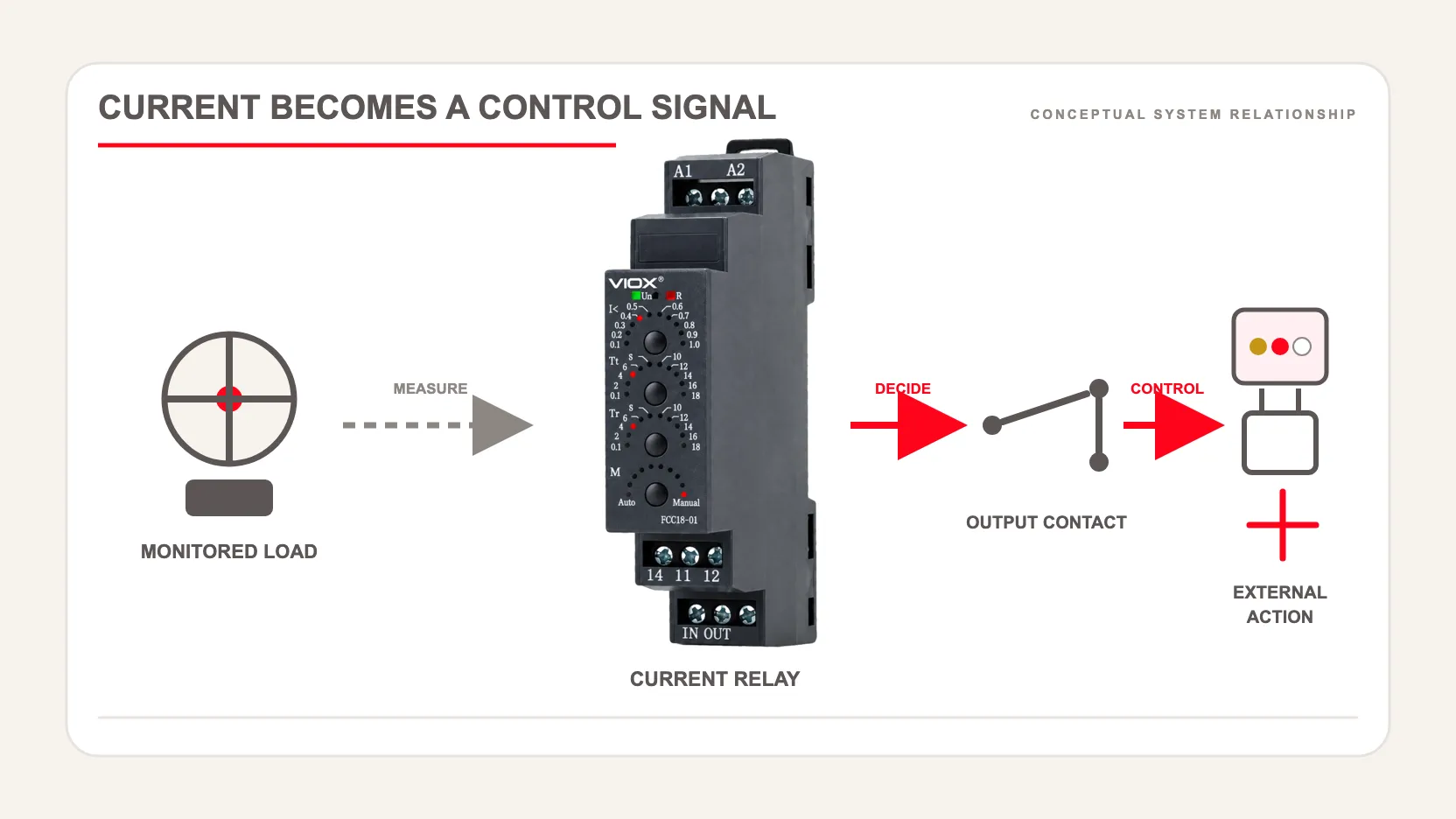
রিলে কারেন্ট মনিটর করে এবং একটি কন্ট্রোল আউটপুট পরিবর্তন করে; একটি বাহ্যিক ডিভাইস চূড়ান্ত কন্ট্রোল অ্যাকশন সম্পাদন করে।.
সুইচিং এবং ইন্টারাপশন ভূমিকার গভীরতর তুলনার জন্য, দেখুন কন্ট্রাক্টর বনাম সার্কিট ব্রেকার. মোটর থার্মাল সুরক্ষার জন্য, আলাদাটি ব্যবহার করুন থার্মাল ওভারলোড রিলে ব্যাখ্যা করা হয়েছে গাইড।.
যে চারটি সেটিংস কার্যপদ্ধতি নির্ধারণ করে
নির্বাচন বা কমিশনিং সংক্রান্ত বেশিরভাগ ভুল হয় কারেন্ট থ্রেশহোল্ডকে একমাত্র সেটিং হিসেবে বিবেচনা করার কারণে। বাস্তবে, চারটি প্যারামিটার রেসপন্স নির্ধারণ করে।.
১. কারেন্ট থ্রেশহোল্ড
শুধুমাত্র মোটরের নেমপ্লেট বা তাত্ত্বিক লোড অনুমানের ওপর ভিত্তি না করে, পরিমাপকৃত স্বাভাবিক অপারেশন থেকে থ্রেশহোল্ড সেট করুন। স্টার্টিং, স্থিতিশীল লোড, সর্বনিম্ন গ্রহণযোগ্য লোড, সর্বোচ্চ গ্রহণযোগ্য লোড এবং প্রতিনিধিত্বমূলক প্রসেস পরিবর্তনের সময় কারেন্ট রেকর্ড করুন। থ্রেশহোল্ডটিকে স্বাভাবিক পরিবর্তনের চেয়ে যথেষ্ট দূরে রাখুন যাতে অনাকাঙ্ক্ষিত অপারেশন না ঘটে, তবে এটি যেন উদ্দিষ্ট অস্বাভাবিক অবস্থা শনাক্ত করার জন্য যথেষ্ট কাছাকাছি থাকে।.
২. ট্রিপ ডিলে
ট্রিপ ডিলে হলো সেই সময়, যা আউটপুট পরিবর্তনের আগে অস্বাভাবিক কারেন্ট অবস্থাকে অবশ্যই বজায় রাখতে হয়। খুব কম ডিলে ইনরাশ বা প্রসেস পিকগুলোকে ফল্ট হিসেবে গণ্য করতে পারে। আবার খুব বেশি ডিলে জ্যাম, ড্রাই রান বা লোড লস অব্যাহত রাখতে পারে। সঠিক মানটি প্রসেস টাইম কনস্ট্যান্ট এবং বিলম্বিত অ্যাকশনের পরিণতির ওপর নির্ভর করে।.
৩. রিসেট কন্ডিশন
স্বয়ংক্রিয় রিসেট সেইসব প্রসেসের জন্য উপযুক্ত যা কারেন্ট স্বাভাবিক অবস্থায় ফিরে আসার পর নিরাপদে পুনরায় শুরু হতে পারে। ম্যানুয়াল রিসেট ফল্ট ইন্ডিকেশন বজায় রাখে এবং স্বীকৃতির প্রয়োজন হয়। যেখানে স্বয়ংক্রিয় রিস্টার্ট বিপদ সৃষ্টি করতে পারে, সেখানে রিসেট আচরণ অবশ্যই মেশিনের নিরাপত্তা এবং রিস্টার্ট ডিজাইনের সাথে সমন্বয় করতে হবে; একটি মনিটরিং রিলে স্বয়ংক্রিয়ভাবে সেফটি রিলে নয়।.
৪. রিসেট ডিলে বা রিস্টার্ট লজিক
কারেন্ট স্বাভাবিক সীমার মধ্যে ফিরে আসার পর দ্রুত সাইক্লিং রোধ করতে একটি রিসেট ডিলে ব্যবহার করা হয়। এটি চাপ, প্রবাহ বা যান্ত্রিক অবস্থার স্থিতিশীল হওয়ার জন্য প্রয়োজনীয় সময়ও প্রদান করতে পারে। কন্টাক্টর ড্রপআউট, PLC লজিক, অ্যালার্ম এবং অনুমোদিত রিস্টার্টসহ সম্পূর্ণ কন্ট্রোল সিকোয়েন্সটি পর্যালোচনা করা উচিত, শুধুমাত্র রিলে কনফিগার করার পরিবর্তে।.
যখন কারেন্ট একটি কার্যকর প্রসেস সিগন্যাল হিসেবে কাজ করে
কারেন্ট মনিটরিং তখনই সবচেয়ে কার্যকর হয় যখন বৈদ্যুতিক লোড সংশ্লিষ্ট যান্ত্রিক বা প্রসেস অবস্থার সাথে সামঞ্জস্য রেখে পরিবর্তিত হয়।.
| কারেন্ট কন্ডিশন | সম্ভাব্য প্রসেস অর্থ | সাধারণ কন্ট্রোল রেসপন্স | যাচাইকরণ প্রয়োজন |
|---|---|---|---|
| কারেন্ট স্বাভাবিকের চেয়ে বৃদ্ধি পায় | জ্যাম, বাইন্ডিং, অতিরিক্ত ফিড, উচ্চ টর্ক চাহিদা | অ্যালার্ম, নিয়ন্ত্রিত স্টপ, আনলোড সিকোয়েন্স | নিশ্চিত করুন যে স্বাভাবিক স্টার্টিং বা কাটিং পিকগুলো ফল্ট অঞ্চলের সাথে ওভারল্যাপ না করে |
| কারেন্ট স্বাভাবিকের নিচে নেমে যায় | ড্রাই-রানিং পাম্প, ছিঁড়ে যাওয়া বেল্ট, যান্ত্রিক লোড হারানো | পাম্প বন্ধ করুন, অ্যালার্ম, স্ট্যান্ডবাইতে সুইচ করুন | নিশ্চিত করুন যে কম-প্রবাহ বা আনলোডেড অপারেশন একটি পুনরাবৃত্তিযোগ্য কারেন্ট পরিবর্তন তৈরি করে |
| কারেন্ট অদৃশ্য হয়ে যায় | ওপেন হিটার, বিচ্ছিন্ন লোড, বন্ধ মোটর | ফল্ট নির্দেশক বা প্রসেস ইন্টারলক | কমান্ডের মাধ্যমে বন্ধ অবস্থা এবং অনিচ্ছাকৃত ওপেন সার্কিটের মধ্যে পার্থক্য করুন |
| কারেন্ট একটি নির্দিষ্ট সীমার মধ্যে থাকে | প্রত্যাশিত অপারেটিং লোড | অপারেশনের অনুমতি দিন বা প্রক্রিয়ার অবস্থা নিশ্চিত করুন | সরবরাহ, তাপমাত্রা এবং পণ্যের পরিবর্তনের ক্ষেত্রে এই সীমাটি যাচাই করুন |
| কারেন্ট একটি সীমার আশেপাশে ওঠানামা করে | অস্থির প্রক্রিয়া বা দুর্বলভাবে পৃথক করা থ্রেশহোল্ড | ডিলে, হিস্টেরেসিস বা ডায়াগনস্টিক পর্যালোচনা | শুধুমাত্র বিলম্ব যোগ করে প্রকৃত যান্ত্রিক অস্থিরতাকে আড়াল করবেন না। |
পাম্প এবং ফ্যান
আন্ডারকারেন্ট হাইড্রোলিক বা অ্যারোডাইনামিক লোড হারানোর ইঙ্গিত দিতে পারে, যার মধ্যে কিছু ড্রাই-রানিং অবস্থাও অন্তর্ভুক্ত। ওভারকারেন্ট ব্লকেজ, বিয়ারিং সমস্যা বা অতিরিক্ত চাপের ইঙ্গিত দিতে পারে। যেহেতু পাম্পের ধরন, স্পিড কন্ট্রোল, তরলের বৈশিষ্ট্য এবং অপারেটিং পয়েন্ট কারেন্টকে প্রভাবিত করে, তাই কমিশনিং পরিমাপ অপরিহার্য।.
কনভেয়র, ক্রাশার এবং মিক্সার
ওভারকারেন্ট মনিটরিং দীর্ঘস্থায়ী বাইন্ডিং বা অতিরিক্ত উপাদান লোড শনাক্ত করতে পারে। আন্ডারকারেন্ট একটি ভাঙা কাপলিং, ভাঙা বেল্ট বা অনুপস্থিত পণ্যের সংকেত দিতে পারে। একটি থ্রেশহোল্ড বিলম্বের মাধ্যমে স্বাভাবিক লোড ধাপগুলো অতিক্রম করা উচিত, তবে যান্ত্রিক পরিণতি অগ্রহণযোগ্য হওয়ার আগেই কাজ করা উচিত।.
হিটার
কারেন্টের উপস্থিতি নিশ্চিত করতে পারে যে একটি হিটার শাখা এনার্জাইজড আছে। প্রত্যাশার চেয়ে কম মান একটি ওপেন এলিমেন্ট বা মাল্টি-এলিমেন্ট ব্যাংকের কোনো ব্যর্থ পর্যায় প্রকাশ করতে পারে। শুধুমাত্র কারেন্ট সরবরাহকৃত তাপমাত্রা নিশ্চিত করে না, তাই এটি তাপমাত্রা সেন্সর এবং তাপমাত্রা-সীমা নির্ধারণকারী ডিভাইসের পরিপূরক হিসেবে কাজ করে, তাদের প্রতিস্থাপন করে না।.
মেশিন টুলস এবং অটোমেটেড স্টেশন
কারেন্ট স্পিন্ডল, অ্যাকচুয়েটর, সোলেনয়েড এবং অন্যান্য লোডের জন্য একটি সাশ্রয়ী লোড বা অপারেশন সিগনেচার প্রদান করতে পারে। এটি পুনরাবৃত্তিযোগ্য প্রক্রিয়ার জন্য সবচেয়ে উপযুক্ত। যদি ফল্ট এবং স্বাভাবিক কারেন্টের ব্যান্ড উল্লেখযোগ্যভাবে ওভারল্যাপ করে, তবে ভাইব্রেশন, চাপ, প্রবাহ, অবস্থান বা পাওয়ার মনিটরিং আরও নির্ভরযোগ্য সংকেত প্রদান করতে পারে।.
কিভাবে একটি কারেন্ট মনিটরিং রিলে নির্বাচন করবেন
অ্যাপ্লিকেশনটিকে একটি গ্রহণযোগ্য স্পেসিফিকেশনে রূপান্তর করতে নিম্নলিখিত ক্রমটি ব্যবহার করুন।.
১. প্রথমে অস্বাভাবিক অবস্থাটি নির্ধারণ করুন
প্রক্রিয়ার ঘটনাটি সহজ ভাষায় বর্ণনা করুন: “একটি ব্লকড কনভেয়ার শনাক্ত করা,” “দীর্ঘক্ষণ লোড না থাকলে পাম্প বন্ধ করা,” অথবা “হিটার চালু করার নির্দেশ দেওয়ার পর সেটি কারেন্ট নিচ্ছে কিনা তা নিশ্চিত করা।” এরপর সিদ্ধান্ত নিন যে ওভারকারেন্ট, আন্ডারকারেন্ট, লস-অফ-কারেন্ট বা উইন্ডো মনিটরিংয়ের মধ্যে কোনটি সেই ঘটনাটিকে সবচেয়ে ভালোভাবে উপস্থাপন করে।.
২. AC বা DC এবং পরিমাপের পরিসীমা মিলিয়ে নিন
মনিটর করা সার্কিটটি AC নাকি DC, প্রাসঙ্গিক ক্ষেত্রে এর ফ্রিকোয়েন্সি এবং প্রত্যাশিত সর্বনিম্ন, স্বাভাবিক, স্টার্টিং ও ফল্ট কারেন্ট নিশ্চিত করুন। স্বাভাবিক অপারেটিং ব্যান্ডটি রিলে-এর অ্যাডজাস্টেবল রেঞ্জের মধ্যে সুবিধাজনকভাবে থাকা উচিত। শুধুমাত্র লোড রেটিংয়ের সাথে সর্বোচ্চ মান মিলে যায় বলেই কোনো রেঞ্জ নির্বাচন করবেন না।.
রিলে কীভাবে কারেন্ট পরিমাপ করে তাও যাচাই করুন। ডিস্টর্টেড ওয়েভফর্ম, ফেজ-অ্যাঙ্গেল কন্ট্রোল, রেকটিফায়ার এবং ভেরিয়েবল-ফ্রিকোয়েন্সি ড্রাইভের ক্ষেত্রে এভারেজ-রেসপন্ডিং এবং ট্রু-RMS পদ্ধতি ভিন্নভাবে কাজ করতে পারে। নির্দিষ্ট কোনো রিলে সেই ওয়েভফর্ম বা অবস্থানের জন্য উপযুক্ত কিনা তা প্রস্তুতকারকের নির্দেশিকা অনুযায়ী নির্ধারিত হয়।.
৩. সরাসরি পরিমাপ অথবা বাহ্যিক সেন্সর নির্বাচন করুন
কিছু রিলে মনিটর করা কন্ডাক্টরকে ডিভাইসের ভেতর দিয়ে অথবা এর কারেন্ট টার্মিনাল দিয়ে নিয়ে যায়। অন্যান্য সিস্টেমে বাহ্যিক কারেন্ট ট্রান্সফরমার বা সেন্সর ব্যবহার করা হয়। সরাসরি পরিমাপ লো-কারেন্ট অ্যাপ্লিকেশনের ক্ষেত্রে সহজ হতে পারে; বাহ্যিক সেন্সর পরিসীমা বাড়াতে বা পৃথকীকরণ প্রদান করতে পারে। সেন্সরের অনুপাত, বার্ডেন, নির্ভুলতা, পোলারিটি এবং সুরক্ষার প্রয়োজনীয়তাগুলো রিলে ইনপুটের সাথে সামঞ্জস্যপূর্ণ হতে হবে।.
যেখানে প্রচলিত CT ব্যবহৃত হয়, সেখানে CT প্রস্তুতকারকের সেকেন্ডারি-সার্কিট সুরক্ষা পদ্ধতি অনুসরণ করুন; ওপেন-সার্কিট টেস্টিং বা ইনস্টলেশনের ক্ষেত্রে নিজে থেকে কোনো পদ্ধতি তৈরি করবেন না।.
৪. মনিটরিং এবং রিসেট ফাংশন নির্বাচন করুন
ওভারকারেন্ট, আন্ডারকারেন্ট, উইন্ডো, ল্যাচিং/ম্যানুয়াল রিসেট বা অটোমেটিক রিসেট নির্দিষ্ট করুন। স্টার্টআপ ইনহিবিশন, আলাদা ট্রিপ এবং রিসেট ডিলে, সাপ্লাই লসের পরে মেমোরি এবং ফেইল-সেফ আউটপুট লজিক প্রয়োজন কিনা তা পরীক্ষা করুন। শুধুমাত্র “Normally open” কন্টাক্ট নোটেশন স্বাভাবিক অপারেশন, অক্সিলিয়ারি সাপ্লাই বিচ্ছিন্ন হওয়া বা মনিটর করা কোনো ত্রুটির সময় আউটপুট অবস্থা ব্যাখ্যা করে না।.
৫. অক্সিলিয়ারি সাপ্লাই যাচাই করুন
রিলে-এর সাপ্লাই ভোল্টেজ মনিটর করা কারেন্ট রেঞ্জ থেকে আলাদা। AC বা DC সাপ্লাই, অনুমোদিত টলারেন্স, ফ্রিকোয়েন্সি, বিদ্যুৎ খরচ এবং অক্সিলিয়ারি সাপ্লাই বিচ্ছিন্ন হলে কী ঘটবে তা নিশ্চিত করুন।.
৬. আউটপুট ইন্টারফেস ডিজাইন করুন
আউটপুটটি কী নিয়ন্ত্রণ করবে তা চিহ্নিত করুন: PLC ইনপুট, ইন্টারপোজিং রিলে, কন্টাক্টর কয়েল, অ্যালার্ম বা শাটডাউন সার্কিট। কন্টাক্ট বিন্যাস, রেটেড ইউটিলাইজেশন ক্যাটাগরি বা DC সুইচিং ডেটা, ন্যূনতম সুইচিং লোড, বৈদ্যুতিক স্থায়িত্ব এবং ইনডাকটিভ কয়েলের জন্য সাপ্রেশন প্রয়োজনীয়তা যাচাই করুন। শুধুমাত্র একটি অ্যাম্পিয়ার ভ্যালু কোনো নির্দিষ্ট কন্টাক্টর কয়েল বা DC লোডের জন্য উপযুক্ততা প্রমাণ করে না।.
৭. নির্ভুলতা এবং পরিবেশ পরীক্ষা করুন
থ্রেশহোল্ডের নির্ভুলতা, পুনরাবৃত্তিযোগ্যতা, তাপমাত্রার প্রভাব, রেসপন্স টাইম, ইন্সটলেশন ক্যাটাগরি, ইনসুলেশন, এনক্লোজার, পলিউশন ডিগ্রি, মাউন্টিং, ভাইব্রেশন এবং প্রযোজ্য অনুমোদনগুলো পর্যালোচনা করুন। বর্তমান ডিভাইসের ম্যানুয়াল এবং স্থানীয় ইন্সটলেশন নিয়মগুলোকে নিয়ন্ত্রণকারী নথি হিসেবে ব্যবহার করুন।.
VIOX FCC18 উদাহরণ: অ্যাপ্লিকেশনের সাথে ফাংশনের সামঞ্জস্য বিধান
দ্য VIOX FCC18 সিঙ্গেল-ফেজ কারেন্ট রিলে একটি প্রোডাক্ট ফ্যামিলি কীভাবে কারেন্ট-মনিটরিংয়ের কাজগুলোকে চারটি কার্যকরী ভেরিয়েন্টে বিভক্ত করতে পারে তা প্রদর্শন করে।.
| FCC18 ভেরিয়েন্ট | প্রকাশিত মনিটরিং ফাংশন | রিসেট পদ্ধতি | উদাহরণস্বরূপ ব্যবহারের ক্ষেত্র |
|---|---|---|---|
| FCC18-01 এর কীওয়ার্ড | অতিরিক্ত প্রবাহ | কারেন্ট প্রকাশিত রিসেট সীমার নিচে নেমে আসার পর স্বয়ংক্রিয়ভাবে | দীর্ঘস্থায়ী অতিরিক্ত লোড বা বাইন্ডিং শনাক্ত করা |
| FCC18-02 এর কীওয়ার্ড | আন্ডারকারেন্ট | কারেন্ট প্রকাশিত রিসেট সীমার উপরে ফিরে আসার পর স্বয়ংক্রিয়ভাবে | লোড হারানো বা ড্রাই-রানিং অবস্থা শনাক্ত করা যেখানে কারেন্ট একটি কার্যকর নির্দেশক |
| FCC18-03 সম্পর্কে | ওভারকারেন্ট এবং আন্ডারকারেন্ট | ম্যানুয়াল রিসেট | অপারেটরের স্বীকৃতির জন্য উচ্চ বা নিম্ন-কারেন্ট ইভেন্ট সংরক্ষণ করা |
| FCC18-04 সম্পর্কে | ওভারকারেন্ট এবং আন্ডারকারেন্ট | স্বয়ংক্রিয় রিসেট | স্বয়ংক্রিয়ভাবে পুনরুদ্ধারযোগ্য প্রক্রিয়ায় অনুমোদিত কারেন্ট উইন্ডো পর্যবেক্ষণ করা |
পুরো ফ্যামিলি জুড়ে, VIOX 0.05–0.5 A থেকে 1.6–16 A পর্যন্ত কারেন্ট-রেঞ্জ ভেরিয়েন্ট এবং 0.1 থেকে 20 সেকেন্ড পর্যন্ত টাইমিং অ্যাডজাস্টমেন্ট প্রকাশ করে। এর স্বয়ংক্রিয়-রিসেট বর্ণনার জন্য, প্রোডাক্ট পেজটি ওভারকারেন্ট অপারেশনের ক্ষেত্রে উচ্চ থ্রেশহোল্ডের 95% এর নিচে এবং আন্ডারকারেন্ট অপারেশনের ক্ষেত্রে নিম্ন থ্রেশহোল্ডের 105% এর উপরে রিটার্ন সীমানা চিহ্নিত করে। এই সংখ্যাগুলো FCC18 ফ্যামিলি পেজের বর্ণনা দেয়; এগুলোকে অন্যান্য কারেন্ট রিলে-র ক্ষেত্রে সাধারণীকরণ করা উচিত নয়।.
সঠিক ভেরিয়েন্টটি এখনও পর্যবেক্ষণকৃত ওয়েভফর্ম, স্বাভাবিক এবং অস্বাভাবিক কারেন্ট পরিমাপ, অক্সিলিয়ারি সাপ্লাই, আউটপুট ডিউটি, রিসেট ফিলোসফি, ইনস্টলেশন শর্তাবলী এবং বর্তমান প্রোডাক্ট ডকুমেন্টেশনের উপর নির্ভর করে। ব্রাউজ করুন VIOX কারেন্ট রিলে রেঞ্জ যখন মনিটরিং ফাংশনটি সংজ্ঞায়িত করা হয়েছে।.
অপ্রয়োজনীয় ট্রিপ ছাড়াই কমিশনিং
একটি সুশৃঙ্খল কমিশনিং প্রক্রিয়া রেটেড কারেন্টের শতাংশ অনুমান করার চেয়ে বেশি নির্ভরযোগ্য।.
- নথিতে উল্লেখ আছে: কমান্ডেড-অফ, স্টার্টআপ, নো-লোড, স্বাভাবিক সর্বনিম্ন, স্বাভাবিক সর্বোচ্চ এবং উদ্দিষ্ট ফল্ট স্টেটগুলোর তালিকা করুন।.
- প্রতিনিধিত্বমূলক কারেন্ট পরিমাপ করুন: সরবরাহের সহনশীলতা, উষ্ণ ও ঠান্ডা সরঞ্জাম এবং বাস্তবসম্মত পণ্য বা প্রক্রিয়ার তারতম্য অন্তর্ভুক্ত করুন।.
- একটি অস্থায়ী থ্রেশহোল্ড সেট করুন: স্বাভাবিক তারতম্য এবং শনাক্তযোগ্য ফল্ট ব্যান্ডের মধ্যে একটি স্পষ্ট মার্জিন বজায় রাখুন।.
- সর্বনিম্ন প্রয়োজনীয় বিলম্ব সেট করুন: প্রক্রিয়ার সর্বোচ্চ গ্রহণযোগ্য ফল্ট ডিউরেশনের মধ্যে থেকে বৈধ ট্রানজিয়েন্টগুলোকে যেতে দিন।.
- সম্পূর্ণ রেসপন্স পরীক্ষা করুন: রিলে ইন্ডিকেশন, আউটপুট স্টেট, কন্টাক্টর বা PLC অ্যাকশন, অ্যালার্মের আচরণ এবং রিসেট সিকোয়েন্স যাচাই করুন।.
- অক্সিলিয়ারি সাপ্লাই বিচ্ছিন্ন হওয়ার পরীক্ষা করুন: নিশ্চিত করুন যে ফলাফলস্বরূপ আউটপুট স্টেটটি কন্ট্রোল ফিলোসফির সাথে সামঞ্জস্যপূর্ণ।.
- সেটিংগুলো রেকর্ড করুন: প্যানেল রেকর্ডের ভেতরে চূড়ান্ত থ্রেশহোল্ড, টাইমিং, রিসেট মোড, পরীক্ষার শর্তাবলী এবং গ্রহণযোগ্যতার ফলাফল নথিবদ্ধ করুন।.
যদি স্বাভাবিক এবং ফল্ট কারেন্ট একে অপরের ওপর আপতিত হয়, তবে বিলম্ব বৃদ্ধি করলে অনাকাঙ্ক্ষিত ট্রিপ কমতে পারে কিন্তু পরিমাপের ক্ষেত্রে কোনো পার্থক্য তৈরি করতে পারে না। সেন্সরের অবস্থান, মূল্যায়নের জন্য ব্যবহৃত মেশিনের অবস্থা অথবা যে প্রসেস ভেরিয়েবল পর্যবেক্ষণ করা হচ্ছে তা পুনর্বিবেচনা করুন।.
কারেন্ট মনিটরিং বনাম ভোল্টেজ মনিটরিং
কারেন্ট উত্তর দেয় “সরঞ্জামটি কতটুকু বৈদ্যুতিক লোড টানছে?” ভোল্টেজ উত্তর দেয় “প্রত্যাশিত সরবরাহ কি উপস্থিত আছে এবং সীমার মধ্যে আছে?” এগুলো ভিন্ন ভিন্ন ফেইলিওর মোড প্রকাশ করে। একটি আটকে যাওয়া মোটর অতিরিক্ত কারেন্ট টানলেও স্বাভাবিক সরবরাহ ভোল্টেজ বজায় রাখতে পারে; একটি ওপেন লোড কোনো কারেন্ট না টানলেও কন্ট্রোল পয়েন্টে ভোল্টেজ বজায় রাখতে পারে। বিপরীতভাবে, ফেজ সিকোয়েন্স, ফেজ লস বা সরবরাহ-ভোল্টেজের সীমা নির্ধারণের কাজগুলো ভোল্টেজ বা ফেজ মনিটরিং ডিভাইসের জন্য।.
ব্যবহার করুন ভোল্টেজ মনিটরিং রিলে গাইড যখন প্রাথমিক ভেরিয়েবলটি লোড কারেন্টের পরিবর্তে সরবরাহের অবস্থা হয়। কিছু সিস্টেমে উভয় পরিমাপের প্রয়োজন হয়, যেখানে PLC বা কন্ট্রোল সার্কিট তাদের আউটপুট সমন্বয় করে।.
ইঞ্জিনিয়ারিং মূল বিষয়সমূহ
একটি কারেন্ট মনিটরিং রিলে মূল্যবান কারণ এটি একটি বৈদ্যুতিক লোড সিগনেচারকে একটি সময়ভিত্তিক কন্ট্রোল সিদ্ধান্তে রূপান্তর করে। নির্ভরযোগ্য প্রয়োগ পাঁচটি পছন্দের ওপর নির্ভর করে: সঠিক প্রসেস সিগন্যাল, উপযুক্ত পরিমাপের পরিসীমা ও পদ্ধতি, স্বাভাবিক পরিবর্তন থেকে আলাদা থ্রেশহোল্ড, প্রকৃত ট্রানজিয়েন্টের সাথে সামঞ্জস্যপূর্ণ বিলম্ব এবং চূড়ান্ত কাজ সম্পাদনকারী ডিভাইসের জন্য প্রকৌশলগতভাবে তৈরি আউটপুট ইন্টারফেস।.
এটিকে কন্ট্রোল এবং প্রোটেকশন আর্কিটেকচারের একটি স্তর হিসেবে বিবেচনা করুন। শর্ট সার্কিট প্রোটেকশন, মোটর অতিভার প্রোটেকশন, সেফটি ফাংশন এবং পাওয়ার সুইচিংয়ের কাজগুলো সেই দায়িত্বের জন্য ডিজাইন করা ও রেটিংপ্রাপ্ত সরঞ্জামের ওপর ন্যস্ত রাখুন।.
Sources Used
- VIOX FCC18-01/2/3/4 একক-ফেজ কারেন্ট রিলে — ফার্স্ট-পার্টি প্রোডাক্ট ফাংশন, পরিসীমা, টাইমিং এবং রিসেট আচরণ।.
- VIOX কারেন্ট রিলে প্রোডাক্ট ক্যাটাগরি — সম্পর্কিত পণ্য পরিবারের প্রেক্ষাপট।.
- IEC 60255-1:2022 — পরিমাপক রিলে এবং সুরক্ষা সরঞ্জামের জন্য সাধারণ প্রয়োজনীয়তা এবং পরিধি।.
- IEC 61869-2:2012 — কারেন্ট ট্রান্সফরমারের জন্য অতিরিক্ত প্রয়োজনীয়তা।.
- আইইসি ৬০৯৪৭-৪-১:২০২৩ — কন্টাক্টর, মোটর স্টার্টার এবং সংশ্লিষ্ট সরঞ্জামের পরিধি।.
- IEC 60947-5-1:2024 — ইলেক্ট্রোমেকানিক্যাল কন্ট্রোল-সার্কিট ডিভাইসের পরিধি।.