
Why Electrical Enclosure Fire Protection Matters
Electrical fires account for approximately 25,000 residential and commercial incidents annually, with distribution panels and control cabinets representing critical fire hazards in industrial facilities. Unlike open-space fires, electrical enclosure fires present unique challenges: confined spaces amplify thermal buildup, energized components complicate suppression efforts, and traditional extinguishing methods often cause collateral damage that exceeds fire-related losses.
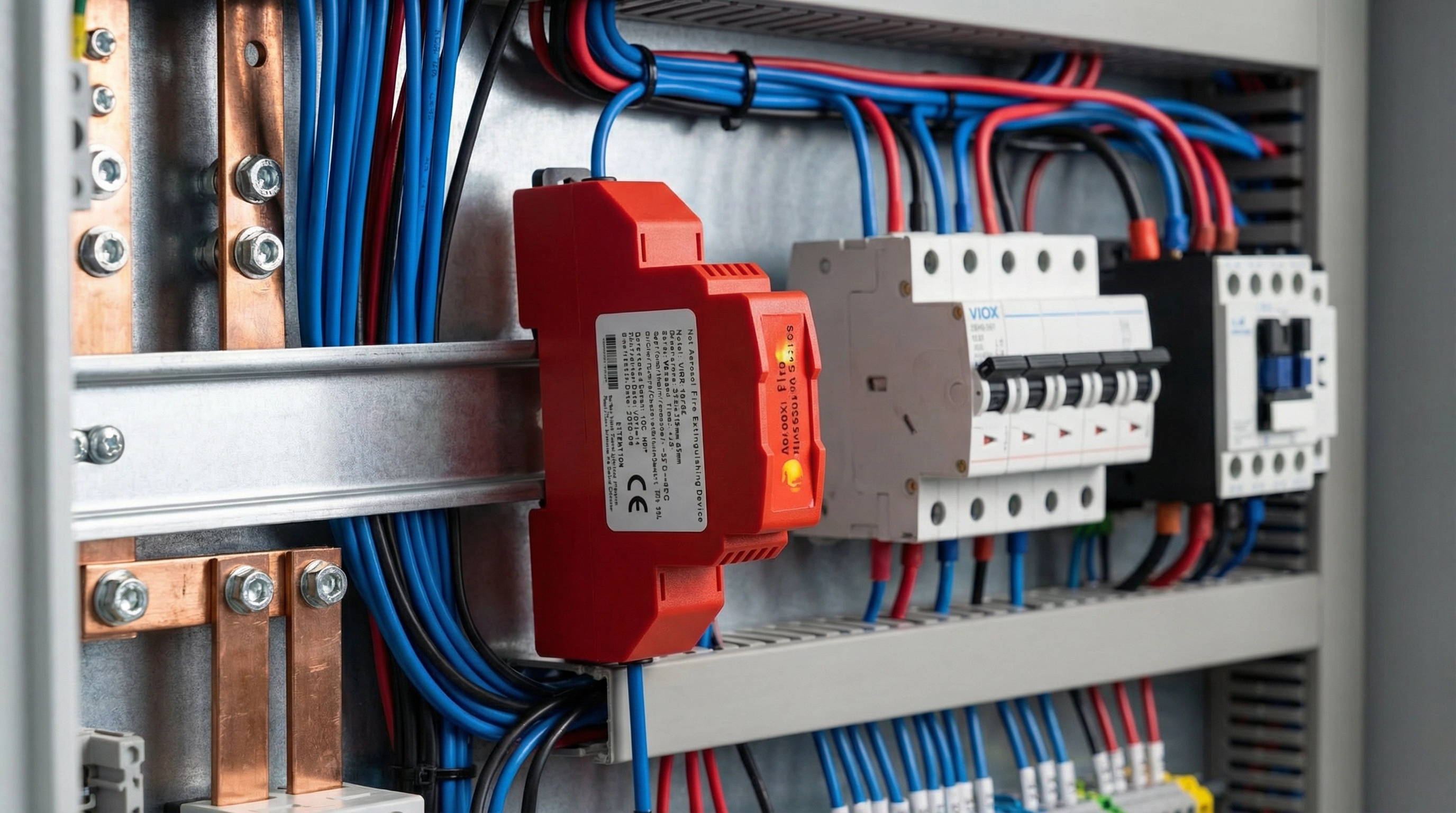
The aerosol fire extinguisher represents a paradigm shift in electrical cabinet fire suppression. These compact, self-contained units deploy ultra-fine potassium-based particles that suppress fires through chemical chain reaction interruption rather than oxygen displacement or cooling. For facility managers specifying fire protection systems, understanding proper sizing ensures adequate protection without over-engineering costs or installation complexity.
This comprehensive guide walks through the technical considerations, calculation methodologies, and product selection criteria for aerosol extinguisher sizing in electrical enclosures, with specific reference to VIOX Electric’s DIN rail-mounted aerosol fire extinguisher systems.
Understanding Aerosol Fire Suppression Technology
How Condensed Aerosol Systems Work
Condensed aerosol fire suppression operates through a three-phase mechanism fundamentally different from conventional extinguishing agents:
Chemical Inhibition: Upon activation, the aerosol-forming compound undergoes rapid thermal decomposition, generating ultra-fine particles (0.1-10 microns) of potassium carbonates and other metal salts. These particles intercept combustion free radicals (H•, OH•, O•) at the molecular level, terminating the chain reaction that sustains fire propagation. Unlike CO₂ or inert gas systems that rely on oxygen displacement, aerosol agents maintain breathable atmosphere levels (typically reducing O₂ by less than 3%).
Physical Cooling: The endothermic decomposition process absorbs significant thermal energy from the flame zone, reducing local temperatures below ignition thresholds for common electrical insulation materials (typically 300-400°C).
Flame Dilution: The dense particulate cloud creates a barrier effect that physically separates fuel sources from oxidizer, providing secondary suppression through flame structure disruption.
Advantages Over Traditional Fire Suppression Methods
| Criterion | Aerosol Systems | CO₂ | Dry Chemical | Water/Foam |
|---|---|---|---|---|
| Electrical Safety | Non-conductive | Non-conductive | Conductive residue | Highly conductive |
| Residue Impact | Minimal fine dust | None | Heavy corrosive powder | Water damage |
| Space Requirements | 18-67mm width | Large cylinders + piping | Medium cylinders | Extensive piping |
| Installation Complexity | DIN rail clip-on | Professional piping | Moderate | Complex wet system |
| Maintenance Frequency | 10-year service life | Annual inspection | 6-12 months | Quarterly testing |
| Environmental Impact | Zero ODP/GWP | High GWP | Moderate ODP | None |
| Activation Speed | <3 seconds | 10-30 seconds | 5-15 seconds | 30-60 seconds |
The aerosol advantage becomes particularly pronounced in electrical distribution applications where space constraints, residue sensitivity, and rapid response requirements converge. VIOX’s aerosol fire extinguishing devices address these specific pain points through form-factor optimization and electrical integration.
Key Sizing Factors for Aerosol Fire Extinguishers
Protected Volume Calculation
Accurate volume determination forms the foundation of proper aerosol system sizing. The basic calculation follows:
V = L × W × H
Where:
- V = Protected volume (m³)
- L = Enclosure length (m)
- W = Enclosure width (m)
- H = Enclosure height (m)
Deduction Considerations: Subtract volumes occupied by:
- Solid permanent structures (bus bars, mounting plates >5mm thickness)
- Large transformers or capacitor banks occupying >15% of enclosure volume
- Equipment creating isolated compartments with restricted aerosol circulation
Do Not Deduct: Space occupied by:
- Cable bundles and wire harnesses (aerosol penetrates between conductors)
- Standard circuit breakers and contactors
- Control relays and terminal blocks
Agent Density Requirements
Aerosol extinguishing effectiveness depends on achieving minimum agent concentration throughout the protected volume. Standard design densities:
| Fire Class | Minimum Density | Typical Application |
|---|---|---|
| Class C (Electrical) | 100-130 g/m³ | Distribution panels, control cabinets |
| Class A (Surface) | 80-100 g/m³ | Cable trays, document storage |
| Class B (Flammable Liquid) | 120-150 g/m³ | Transformer oil, hydraulic systems |
For electrical enclosures, VIOX systems target 100 g/m³ as the baseline concentration, with safety factors built into product capacity ratings.
Environmental Compensation Factors
Real-world installations require adjustment for operational conditions:
K₁ (Height Distribution Factor): Accounts for aerosol settling in tall enclosures
- Enclosures <1.5m height: K₁ = 1.0
- 1.5-3.0m height: K₁ = 1.1-1.2
- > 3.0m height: K₁ = 1.3-1.5
K₂ (Leakage Compensation Factor): Adjusts for enclosure integrity
- Gasketed/sealed cabinets: K₂ = 1.0
- Standard electrical enclosures: K₂ = 1.1-1.2
- Ventilated/perforated panels: K₂ = 1.3-1.5 (or not suitable)
Complete Sizing Formula:
M = K₁ × K₂ × V × q
Where:
- M = Required agent mass (grams)
- q = Design density (100 g/m³ for electrical)
- V = Net protected volume (m³)
VIOX Aerosol Fire Extinguisher Product Range
QRR Series Technical Specifications
VIOX Electric manufactures a comprehensive range of aerosol fire suppression devices optimized for electrical distribution applications:
| Model | Agent Mass | Protected Volume | Dimensions (L×W×H) | Mounting Type |
|---|---|---|---|---|
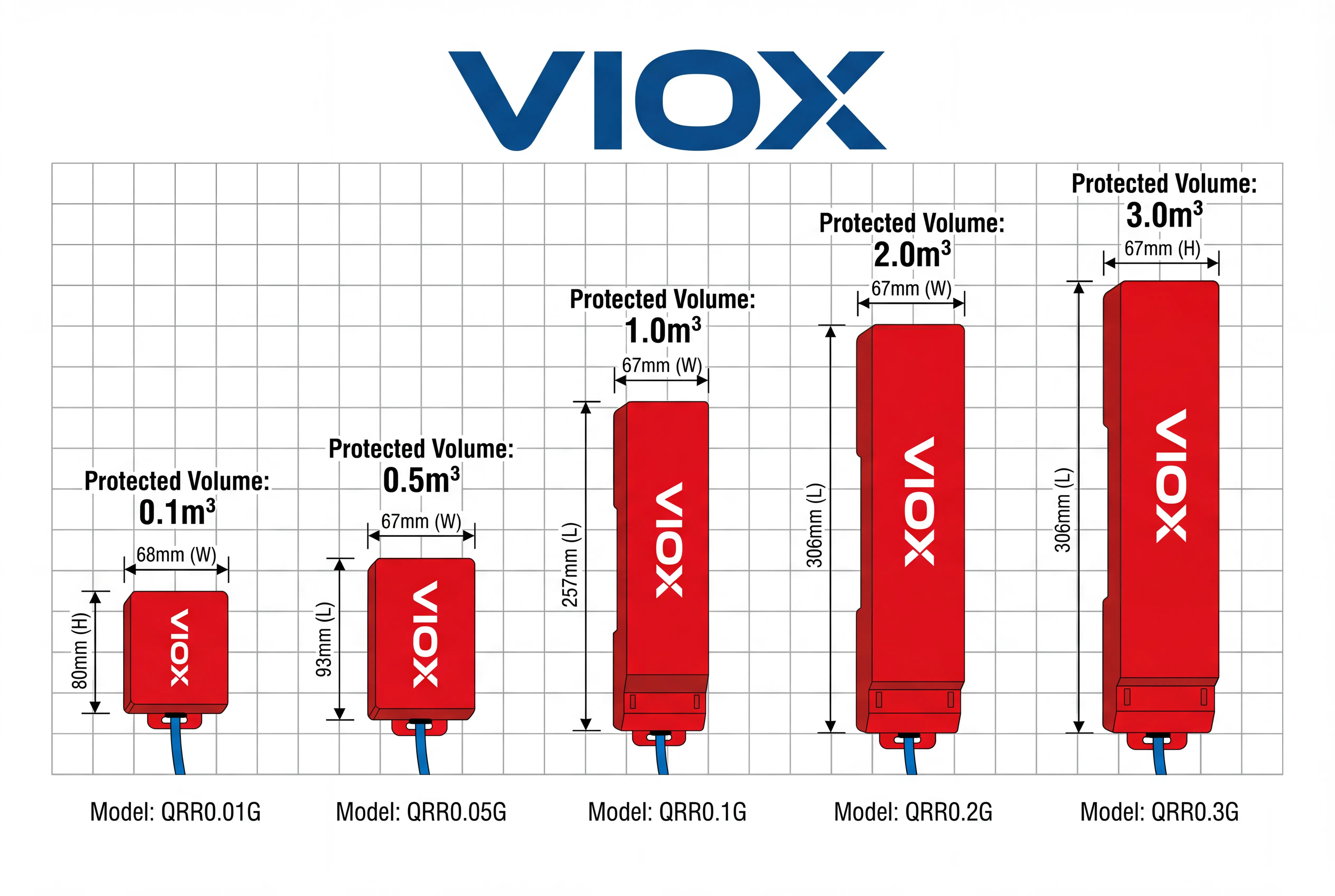
| QRR0.01G/S | 10g ± 1g | ≤0.1 m³ | 80×68×20mm | DIN rail (1P) |
| QRR0.05G/S | 50g ± 2g | ≤0.5 m³ | 93×67×47mm | Magnetic/screw |
| QRR0.1G/S | 100g ± 2g | ≤1.0 m³ | 257×67×47mm | Magnetic/screw |
| QRR0.2G/S | 200g ± 2g | ≤2.0 m³ | 306×67×47mm | Magnetic/screw |
| QRR0.3G/S | 300g ± 2g | ≤3.0 m³ | 306×67×47mm | Magnetic/screw |
Performance Characteristics
Activation Methods:
- Thermal cord detection (1.5m heat-sensitive cable, 170°C ± 5°C activation)
- Electrical activation (12-24VDC signal from fire alarm panel)
- Manual emergency button (break-glass or push-button)
Discharge Performance:
- Spray time: ≤14 seconds (full agent release)
- Response delay: ≤0.5 seconds (from trigger to discharge initiation)
- Nozzle temperature: ≤75°C at 400mm distance (safe for adjacent equipment)
Operating Environment:
- Temperature range: -40°C to +70°C (all models maintain functionality across extreme conditions)
- Humidity tolerance: <95% RH non-condensing
- Vibration resistance: Suitable for mobile applications (tested to IEC 60068-2-6)
Service Life: 10-year maintenance-free operation with factory seal intact
Step-by-Step Sizing Guide with Practical Examples
Example 1: Standard Distribution Cabinet
Application: Low-voltage distribution panel in commercial building
- Enclosure dimensions: 600mm (H) × 400mm (W) × 300mm (D)
- Configuration: Standard ventilated enclosure with MCBs and RCCBs
- Temperature: Indoor controlled environment (20-30°C)
Calculation Steps:
- Volume Calculation:
- V = 0.6m × 0.4m × 0.3m = 0.072 m³
- Factor Determination:
- K₁ = 1.0 (height <1.5m)
- K₂ = 1.1 (standard ventilated enclosure)
- Required Agent Mass:
- M = 1.0 × 1.1 × 0.072 × 100 = 7.92 grams
- Product Selection:
- Recommended: QRR0.01G/S (10g capacity)
- Provides 26% safety margin
- DIN rail mounting integrates directly with existing electrical components
- Single-pole (18mm) width preserves panel space
Example 2: Control Panel with Dense Equipment
Application: PLC control cabinet in industrial automation system
- Enclosure dimensions: 800mm × 600mm × 400mm
- Equipment density: ~30% volume occupied by PLC modules, power supplies
- Environment: Factory floor with temperature variations
Calculation Steps:
- Gross Volume: 0.8m × 0.6m × 0.4m = 0.192 m³
- Equipment Deduction: 0.192 × 0.7 = 0.134 m³ (net volume, accounting for 30% equipment occupation)
- Environmental Factors:
- K₁ = 1.0 (height acceptable)
- K₂ = 1.2 (industrial environment, moderate leakage)
- Required Agent: M = 1.0 × 1.2 × 0.134 × 100 = 16.08 grams
- Product Selection:
- Recommended: QRR0.05G/S (50g capacity)
- Significant safety margin accommodates future equipment additions
- Magnetic mounting allows flexible positioning
- 1.5m thermal cable can route throughout cabinet interior
Example 3: Large Switchgear Cabinet
Application: Medium-voltage switchgear compartment
- Enclosure dimensions: 2000mm × 800mm × 600mm
- Configuration: Sealed metal-clad enclosure with SF6 circuit breaker
- Special consideration: High-value equipment requires maximum protection
Calculation Steps:
- Volume: 2.0m × 0.8m × 0.6m = 0.96 m³
- Height Factor: K₁ = 1.2 (2m height requires distribution compensation)
- Enclosure Factor: K₂ = 1.0 (sealed construction)
- Required Agent: M = 1.2 × 1.0 × 0.96 × 100 = 115.2 grams
- Product Selection:
- Recommended: QRR0.2G/S (200g capacity)
- Oversizing ensures complete suppression in large volume
- Two units can be installed for redundancy (100g each, strategically positioned)
- Alternative: Single QRR0.2G/S with centralized mounting
Installation Considerations for Optimal Protection
DIN Rail Mounting Guidelines
The QRR0.01G/S model’s DIN rail compatibility represents a breakthrough in electrical panel integration:
Mounting Process:
- Confirm 35mm DIN rail availability (standard EN 60715 profile)
- Position unit within upper third of enclosure for optimal aerosol distribution
- Snap unit onto rail using standard clip mechanism (identical to circuit breaker installation)
- Verify 500mm clearance in front of discharge nozzle
- Route thermal detection cable in serpentine pattern covering all cable bundles and connection points
Electrical Integration:
- Standalone operation: Thermal cord provides autonomous fire detection (no external power required)
- Integrated operation: Connect 12V/24V DC signal from fire alarm panel to electrical activation terminals
- Status monitoring: Optional contact output for SCADA/BMS integration
Placement Strategy for Maximum Effectiveness
Vertical Positioning:
- Preferred: Upper 1/3 of enclosure (aerosol naturally disperses downward)
- Acceptable: Middle mounting for tall cabinets (>1.5m)
- Avoid: Bottom mounting (reduces effectiveness, requires increased agent mass)
Horizontal Orientation:
- Discharge nozzle should face toward center of protected volume
- Maintain 300mm minimum distance from protected equipment (prevents thermal shock)
- For multiple units: stagger positions to ensure overlapping coverage zones
Thermal Cord Routing:
- Cover all cable entry points (highest fire probability zones)
- Route through densest wiring areas in serpentine pattern
- Secure with cable ties at 150-200mm intervals
- Avoid sharp bends (>90°) that could damage sensing element
- Excess cable can be trimmed (1.5m standard length accommodates most installations)
Clearance Requirements:
| Zone | Minimum Distance | Reason |
|---|---|---|
| Discharge nozzle to personnel access | 1.5m | Thermal safety during activation |
| Nozzle to protected equipment | 0.3m | Prevents thermal damage to components |
| Nozzle clearance (unobstructed) | 0.5m | Ensures proper aerosol dispersion pattern |
| Side/rear clearances | 50mm | Allows airflow for thermal management |
Multi-Unit Configurations
For enclosures exceeding single-unit capacity, implement distributed suppression:
Series Configuration (single detection zone):
- Multiple aerosol units connected to single thermal cord
- Simultaneous activation ensures uniform concentration
- Suitable for regular rectangular enclosures
Zone Configuration (segregated detection):
- Individual thermal cords per unit
- Targeted suppression reduces unnecessary discharges
- Optimal for compartmentalized switchgear
Example: 3.0 m³ enclosed switchgear
- Option A: Single QRR0.3G/S unit (centrally mounted)
- Option B: Three QRR0.1G/S units (distributed at 1m intervals)
- Option B provides faster response and better distribution in elongated enclosures
Product Comparison and Selection Matrix
Capacity-Based Selection Chart
Application-Specific Recommendations
| Application Type | Typical Volume Range | Recommended Model | Installation Notes |
|---|---|---|---|
| Meter boxes | 0.05-0.15 m³ | QRR0.01G/S | DIN rail mount, thermal cord mandatory |
| Distribution panels | 0.2-0.5 m³ | QRR0.05G/S | Magnetic mount acceptable, dual activation preferred |
| Motor control centers | 0.5-1.2 m³ | QRR0.1G/S | Upper mounting, consider multiple units for >0.8m³ |
| Drive cabinets (VFD) | 1.0-2.5 m³ | QRR0.2G/S | Account for heat generation zones, electrical activation recommended |
| Switchgear compartments | 2.0-3.5 m³ | QRR0.3G/S | Sealed installations, may require dual units for redundancy |
| Server racks | Variable | Per calculation | Assess equipment density, sealed rear preferred |
| Battery enclosures | 0.3-1.5 m³ | Based on volume | Enhanced thermal monitoring due to lithium-ion risks |
Decision Tree for Product Selection
Start Here → Measure Enclosure Volume
If V ≤ 0.1 m³:
- → Standard panel → QRR0.01G/S
- → Dense equipment → Calculate net volume → Select based on adjusted value
If 0.1 m³ < V ≤ 0.5 m³:
- → QRR0.05G/S (standard choice)
- → High-value equipment → Consider QRR0.1G/S for safety margin
If 0.5 m³ < V ≤ 1.0 m³:
- → QRR0.1G/S
- → Tall enclosure (>1.5m) → Use K₁ factor → May require QRR0.2G/S
If 1.0 m³ < V ≤ 2.0 m³:
- → QRR0.2G/S (single unit)
- → Consider 2× QRR0.1G/S for distributed coverage
If 2.0 m³ < V ≤ 3.0 m³:
- → QRR0.3G/S
- → Complex geometry → Multiple smaller units preferred
If V > 3.0 m³:
- → Multiple units required
- → Consider larger aerosol generators for whole-room protection
- → Consult VIOX engineering for system design
Frequently Asked Questions
Q: Can aerosol fire extinguishers be used in continuously occupied electrical rooms?
A: Yes, with proper safety protocols. Aerosol systems maintain oxygen levels above 18% during discharge (compared to CO₂ systems that reduce O₂ to dangerous levels). However, installations should include:
- Pre-discharge alarms (10-30 second evacuation warning)
- Emergency shutdown of HVAC to prevent aerosol dispersal
- Post-discharge ventilation procedures before re-entry
- Personnel training on aerosol exposure (mild eye/respiratory irritation possible)
The VIOX systems comply with ISO 15779 safety standards for occupied space protection when properly configured with detection delays and warning systems.
Q: How do I determine if my enclosure leakage rate requires compensation?
A: Apply the “visual inspection method” for preliminary assessment:
- Sealed enclosures (gasketed doors, sealed cable entries): K₂ = 1.0
- Standard panels (typical gaps around doors/vents <5mm total): K₂ = 1.1-1.2
- Ventilated (louvers, fan openings, perforated panels): K₂ = 1.3-1.5 or not suitable
For critical applications, conduct a door fan test per NFPA 2001 Annex C: target equivalent leakage area (ELA) <0.01 m² per m³ of volume for aerosol system suitability.
Q: What maintenance does a VIOX aerosol extinguisher require during its 10-year service life?
A: Maintenance requirements are minimal compared to conventional systems:
- Monthly: Visual inspection of pressure indicator (green zone), check for physical damage, verify thermal cord integrity
- Quarterly: Test electrical activation circuit (if installed), inspect mounting security
- Annually: Professional inspection documenting unit serial numbers, installation dates, activation system functionality
- No recharging required: Sealed units maintain pressure without annual recertification
After 10 years or any activation event, units must be replaced. The QRR series uses tamper-evident seals that indicate if unauthorized access has occurred.
Q: Can multiple aerosol units be connected to a single fire alarm panel?
A: Yes, VIOX aerosol extinguishers support multiple integration architectures:
Parallel Activation: All units receive simultaneous 12/24VDC signal from single relay output (common for distributed protection in same fire zone)
Zone-Selective Activation: Individual units controlled by separate detection zones (optimal for compartmentalized equipment)
Hybrid Configuration: Thermal cord provides local autonomous protection + electrical activation enables remote manual release
Electrical specifications:
- Input: 12-24VDC (3-5W momentary, <500mW standby)
- Activation: 50-200ms pulse duration required
- Output: Dry contact (SPDT) for system feedback/monitoring
Q: What happens to electrical equipment after aerosol discharge?
A: Post-discharge cleanup and restoration procedures:
Immediate Effects (0-4 hours):
- Fine white/gray dust settles on surfaces (potassium carbonate, carbonates)
- No corrosive action on metal or electronic components (neutral pH)
- Residue is non-conductive in dry state (hygroscopic if exposed to moisture)
Cleanup Procedures:
- De-energize protected equipment
- Vacuum loose residue using HEPA-filtered equipment (avoid blowing or brushing which disperses particles)
- Wipe surfaces with dry cloth or isopropyl alcohol for sensitive electronics
- Inspect for heat damage from original fire (aerosol itself causes no thermal damage)
- Confirm insulation resistance before re-energization
Equipment Impact Studies: NIST testing demonstrates electronic equipment functionality maintained with aerosol residue levels up to 3× typical discharge concentrations, provided moisture ingress is prevented.
Q: How do I size aerosol protection for an enclosure with variable equipment loading?
A: Design for maximum anticipated configuration using conservative approach:
Method 1 – Future-Proof Sizing:
- Calculate based on empty enclosure volume
- Select next-larger capacity model
- Example: 0.4 m³ cabinet → Use QRR0.1G/S instead of QRR0.05G/S
Method 2 – Phased Protection:
- Install capacity matching current equipment (with 20% margin)
- Add supplementary units as equipment density increases
- Example: 1.5 m³ initially requiring 165g → Install QRR0.2G/S now, add second unit if expansion exceeds 1.8 m³
Method 3 – Modular Approach:
- Use multiple smaller units distributed strategically
- Allows selective activation in zone-based detection schemes
- Example: 2.0 m³ → Two QRR0.1G/S units instead of one QRR0.2G/S
For equipment with seasonal/operational variations (e.g., added modules during peak production), size for maximum configuration to avoid mid-lifecycle system modifications.
Conclusion: Implementing Effective Aerosol Fire Protection
Selecting the appropriate aerosol fire extinguisher size for electrical enclosures demands systematic evaluation of protected volume, environmental conditions, equipment density, and operational requirements. The VIOX QRR series provides scalable solutions from compact 0.1 m³ distribution panels to 3.0 m³ switchgear compartments, with DIN rail integration simplifying installation in space-constrained applications.
Key takeaways for specification professionals:
- Always calculate net protected volume accounting for major equipment obstructions and apply appropriate compensation factors (K₁, K₂) for height and leakage
- Select capacity with 15-25% safety margin to accommodate minor calculation variations and future equipment modifications
- Prioritize proper placement (upper third mounting, unobstructed discharge zones, comprehensive thermal cord coverage) over raw agent quantity
- Consider multi-unit distributed configurations for enclosures exceeding 1.5 m³ or irregular geometries to ensure uniform aerosol concentration
- Integrate with existing fire alarm systems where available, while maintaining autonomous thermal activation as backup protection
The economic advantages of aerosol technology—elimination of piping infrastructure, extended maintenance intervals, residue-free discharge, and compact form factors—make VIOX systems particularly compelling for retrofit applications where traditional suppression methods impose prohibitive costs or space constraints.
Ready to Protect Your Electrical Infrastructure?
VIOX Electric provides complete technical support for aerosol fire suppression system design, including:
- Free volume calculation assistance for complex enclosure geometries
- CAD integration support for panel layout optimization
- Custom activation system design for facility-wide fire alarm integration
- Compliance documentation for AHJ approval (NFPA 2010, UL 2775, ISO 15779)
Visit VIOX DIN Rail Aerosol Fire Extinguisher product page for detailed specifications, installation manuals, and direct purchasing options. For application-specific guidance, contact VIOX technical sales at [contact information] or request a site assessment to receive tailored recommendations for your facility’s electrical fire protection requirements.
Don’t wait for a catastrophic electrical fire to expose protection gaps—implement proven aerosol suppression technology that safeguards equipment while minimizing business disruption.
