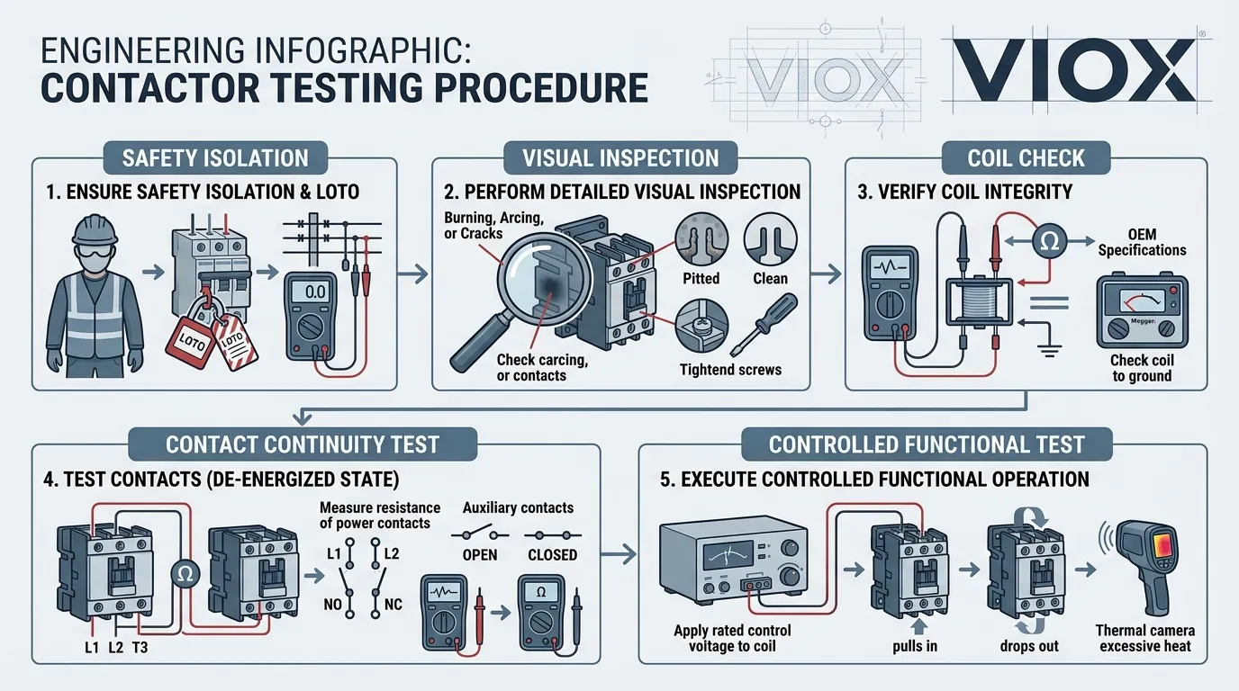
To test a contactor properly, start with the simplest checks first: isolate power, inspect the device visually, verify the coil circuit, check contact continuity, and then confirm switching behavior under the correct control conditions. In most cases, a bad contactor shows up through one or more of these symptoms:
- the coil does not pull in
- the contacts do not close or open correctly
- the contactor chatters or hums abnormally
- the contacts show overheating, burning, or severe wear
- the output side does not follow the control signal
The key is to test the contactor in a logical order instead of jumping straight to replacement.
Key Takeaways
- Always begin with lockout/tagout and voltage verification.
- A good contactor test sequence is: visual check -> coil check -> continuity/contact check -> controlled functional check.
- Coil problems, worn contacts, weak control voltage, and mechanical sticking are the most common causes of failure.
- Do not rely on one reading alone. A contactor can have a good coil and still fail because of damaged contacts or a weak moving mechanism.
- If the contact surfaces are badly damaged or the moving assembly is unreliable, replacement is usually more practical than repair.
What You Are Actually Testing
A contactor is not one single test point. It is a device with several failure areas:
- the coil
- the main contacts
- the auxiliary contacts
- the moving mechanism
- the terminal connections
- the control circuit feeding the coil
That is why a useful testing method has to separate:
- coil failure
- contact failure
- control-supply failure
- mechanical sticking
If you need background on device construction first, see What Is a Contactor? and Inside AC Contactor Components Design Logic.
Safety Before Testing
Before any test, make the circuit safe.
Minimum safety steps
- isolate the supply
- apply lockout/tagout
- verify absence of voltage with an appropriate meter
- discharge stored energy if present
- follow site arc-flash and PPE requirements
If an energized functional check is required later, it should only be done by qualified personnel following the site procedure.
Tools Needed
The exact tool set depends on how deep the diagnosis needs to go, but a practical field setup usually includes:
- digital multimeter
- continuity or resistance function
- insulated test probes
- control schematic or wiring diagram
- insulation resistance tester when insulation condition is in question
- clamp meter if control current or line current behavior needs to be checked
For product evaluation after diagnosis, see the VIOX AC Contactor product page.
Step 1: Start With the Symptom
Before touching the device, define the actual complaint.
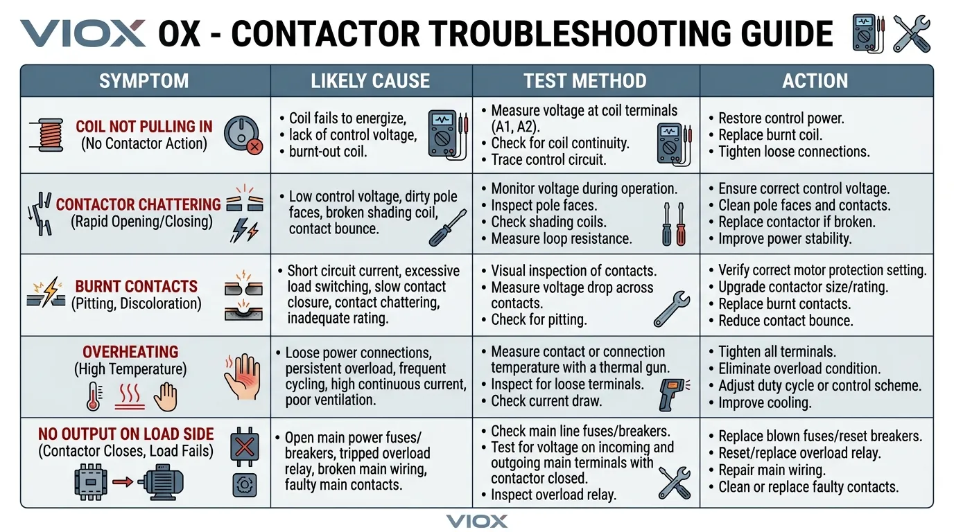
Common symptom patterns include:
- the contactor does not pull in at all
- the contactor pulls in but the load does not energize
- the contactor chatters
- the contactor gets hot
- the contactor remains stuck
- the load drops out intermittently
This matters because different symptoms point to different test priorities.
| Symptom | First Thing to Check |
|---|---|
| Coil does not pull in | Control voltage and coil condition |
| Coil pulls in but load stays off | Main contacts and line/load continuity |
| Chattering or humming | Weak control voltage, incorrect coil rating, mechanical wear |
| Overheating | Contact wear, overload condition, loose terminals |
| Stuck closed or unreliable release | Mechanical damage or welded contacts |
Step 2: Perform a Visual Inspection
Visual inspection is the fastest way to catch obvious failure.
Check for:
- cracked or melted housing
- discoloration
- burnt smell
- loose terminals
- carbon buildup
- pitted or welded contacts
- dust, oil, or contamination
- damaged auxiliary blocks
Also check whether the contactor has been replaced previously with the wrong coil voltage or wrong application class.
If the contactor is badly overheated or physically damaged, deeper electrical testing may only confirm what is already obvious.
Step 3: Verify the Coil Circuit
If the contactor does not pull in, the first serious test is usually the coil circuit.
What to check
- Is the correct control voltage reaching the coil terminals?
- Does the coil have continuity?
- Is the coil rated for the actual control system voltage and frequency?
Practical sequence
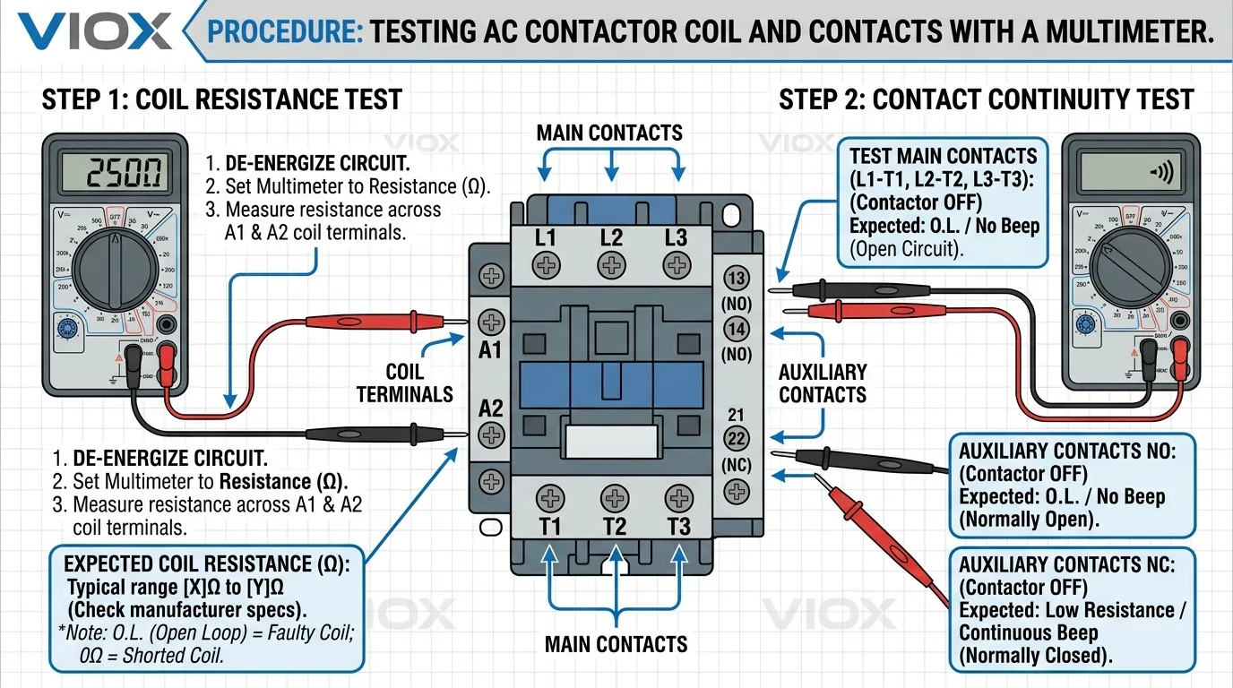
- Identify the coil terminals, usually marked
A1andA2. - Compare the coil rating on the device nameplate with the control circuit.
- With power isolated, check coil continuity or resistance.
- If safe and permitted, confirm whether the correct control voltage appears at the coil when the command is given.
What the result means
- No continuity can indicate an open coil.
- Unexpectedly low resistance can suggest coil damage.
- No control voltage at the coil may indicate the problem is upstream in the control circuit, not inside the contactor itself.
This is why “the contactor is bad” should never be assumed before checking whether the coil is actually being told to operate.
For broader device differences, see AC vs DC Contactors: Understanding Their Types and Functions.
Step 4: Check Main Contacts and Auxiliary Contacts
If the coil is operating but the load side is not behaving correctly, move to the contacts.
With the contactor de-energized
Check whether the contact state matches the normal condition:
- main power contacts should be open on a standard contactor
- NO auxiliary contacts should be open
- NC auxiliary contacts should be closed
With the contactor energized
Check whether:
- the main contacts close properly
- auxiliary contacts change state correctly
- there is continuity through the intended contact path
What to look for
- no continuity when the contact should be closed
- unstable or intermittent continuity
- obvious pitting or burn damage
- signs that contacts are sticking or welding
If the moving mechanism pulls in but the contact path is poor, the problem is often contact wear, contamination, or contact damage rather than the coil.
Step 5: Check for Mechanical Movement Problems
A contactor can fail mechanically even if the coil and contacts look reasonable on a meter.
Inspect:
- armature movement
- return spring action
- sticking or binding
- contamination in the magnetic path
- incomplete travel
Common field symptoms include:
- humming without full pull-in
- partial pull-in
- delayed release
- repeated chattering
If the mechanism is not moving cleanly, contact readings can become misleading because the real fault is mechanical.
Step 6: Inspect Terminal Tightness and Heat Damage
Loose power or coil terminals can imitate a bad contactor.
Check for:
- overheated terminals
- discolored conductor ends
- loose screws or clamps
- damaged lugs
- insulation darkening near the contactor
Sometimes the contactor itself is still functional, but poor terminal connection has caused the symptom.
Step 7: Perform a Controlled Functional Test
If the device passes the basic dead tests and site conditions allow it, perform a controlled functional check.
During the functional check, verify:
- the coil receives the correct control command
- the contactor pulls in cleanly
- the load side follows the contactor state
- the contactor releases correctly
- there is no abnormal chattering, delay, or overheating trend
Do not treat this as a “just energize it and see” step. The purpose is to confirm whether the contactor operates correctly under the real control sequence.
Step 8: Decide Whether the Fault Is the Contactor or the Circuit Around It
This is where many technicians lose time.
A contactor may appear bad when the real problem is:
- missing control voltage
- faulty overload relay reset condition
- open interlock circuit
- PLC or control relay problem
- wrong coil voltage
- broken control transformer output
If the coil never gets the proper command, replacing the contactor will not solve the outage.
What the Results Mean
| Test Result | Likely Meaning | Typical Next Action |
|---|---|---|
| Coil has no continuity | Open or failed coil | Replace contactor or coil assembly if applicable |
| Coil is healthy but never receives command voltage | Upstream control fault | Troubleshoot control circuit |
| Coil pulls in but main contacts do not pass power reliably | Worn, burnt, or damaged contacts | Replace contactor |
| Main contacts work, but chatter occurs | Weak or unstable control supply, mechanical issue, wrong coil rating | Check control voltage and mechanism |
| Severe heat marks or welded contacts | Advanced wear or fault damage | Replace contactor |
| Terminals overheated but contactor otherwise functional | Loose or poor termination | Correct connection and inspect for damage |
When to Replace Instead of Repair
In practice, a contactor is usually replaced instead of repaired when:
- contacts are badly burnt or welded
- the moving mechanism is unreliable
- the coil is failed
- the housing is heat-damaged
- repeated faults have already occurred
Minor cleaning may help in limited cases, but heavily worn contactors are usually not worth trusting in service.
If you are at the replacement stage, compare against the VIOX AC Contactor range and review the surrounding circuit design. In many motor-control systems, the contactor should also be considered together with the upstream protection. For that design context, see Contactor vs Circuit Breaker and How to Select Contactors and Circuit Breakers Based on Motor Power.
A Smarter Testing Order for Field Work
If the goal is speed, this order usually works best:
- Confirm the complaint.
- Isolate and make the circuit safe.
- Perform visual inspection.
- Check coil continuity and coil command voltage.
- Check main and auxiliary contact behavior.
- Inspect terminal tightness and heat damage.
- Perform controlled live verification if required.
- Decide: contactor fault, surrounding control fault, or system fault.
That workflow is faster and more reliable than starting with deep measurements before checking the obvious.
Related Contactor Topics
- What Is a Contactor?
- AC vs DC Contactors
- Inside AC Contactor Components Design Logic
- How to Choose the Right Surge Suppressor for a Contactor Coil
- AC Contactor Product Page
Conclusion
If you want to know how to test a contactor, the practical answer is to test it in layers: visual condition, coil condition, contact behavior, mechanical movement, terminal condition, and real operating response.
A good diagnosis does not stop at “the contactor does not work.” It identifies whether the real fault is:
- the coil
- the contacts
- the mechanism
- the control circuit
- or the surrounding installation
That is what turns contactor testing from guesswork into reliable troubleshooting.
FAQ
How do you test a contactor with a multimeter?
Use the multimeter to verify coil continuity, check whether the correct control voltage reaches the coil, and check continuity across the relevant contacts in both de-energized and energized conditions where safe and permitted.
How do I know if a contactor is bad?
Common signs include failure to pull in, burnt or pitted contacts, chattering, overheating, welded contacts, and a mismatch between the control signal and the output behavior.
Can a contactor test good on the coil but still be bad?
Yes. A contactor can have a healthy coil but still fail because of damaged contacts, mechanical sticking, loose terminals, or control-circuit problems.
What causes a contactor to chatter?
Chattering is often caused by weak or unstable control voltage, incorrect coil rating, mechanical wear, or contamination in the magnetic assembly.
Should I repair or replace a bad contactor?
If the device has severe contact damage, heat damage, a failed coil, or unreliable movement, replacement is usually the safer and more practical choice.
Do I need to remove the contactor to test it?
Not always. Many useful checks can be performed in place. However, some inspections become easier or more reliable when the device is isolated and removed from the circuit.
