
When specifying a switch-disconnector or load-break switch for an electrical installation, you’ll encounter four cryptic designations in the manufacturer’s datasheet: AC-20A, AC-21A, AC-22A, and AC-23A. These aren’t arbitrary codes—they represent the IEC 60947-3 utilization categories, a classification system that defines what type of electrical load each switching device is designed to handle.
The distinction matters profoundly. A switch rated for AC-21A (resistive loads like heaters) will fail prematurely if applied to AC-23A duty (motor switching with high inrush currents). Yet many engineers select switching devices based solely on current rating, overlooking the utilization category entirely. The consequence: nuisance failures, shortened equipment life, and safety hazards from devices operating beyond their design limits.
For electrical engineers designing motor control systems, panel builders selecting switching devices, and maintenance professionals replacing failed equipment, understanding utilization categories is essential. This guide explains the IEC 60947-3 classification system, the characteristics and applications of each category, and practical criteria for matching switching devices to their intended loads.
What is IEC 60947-3?
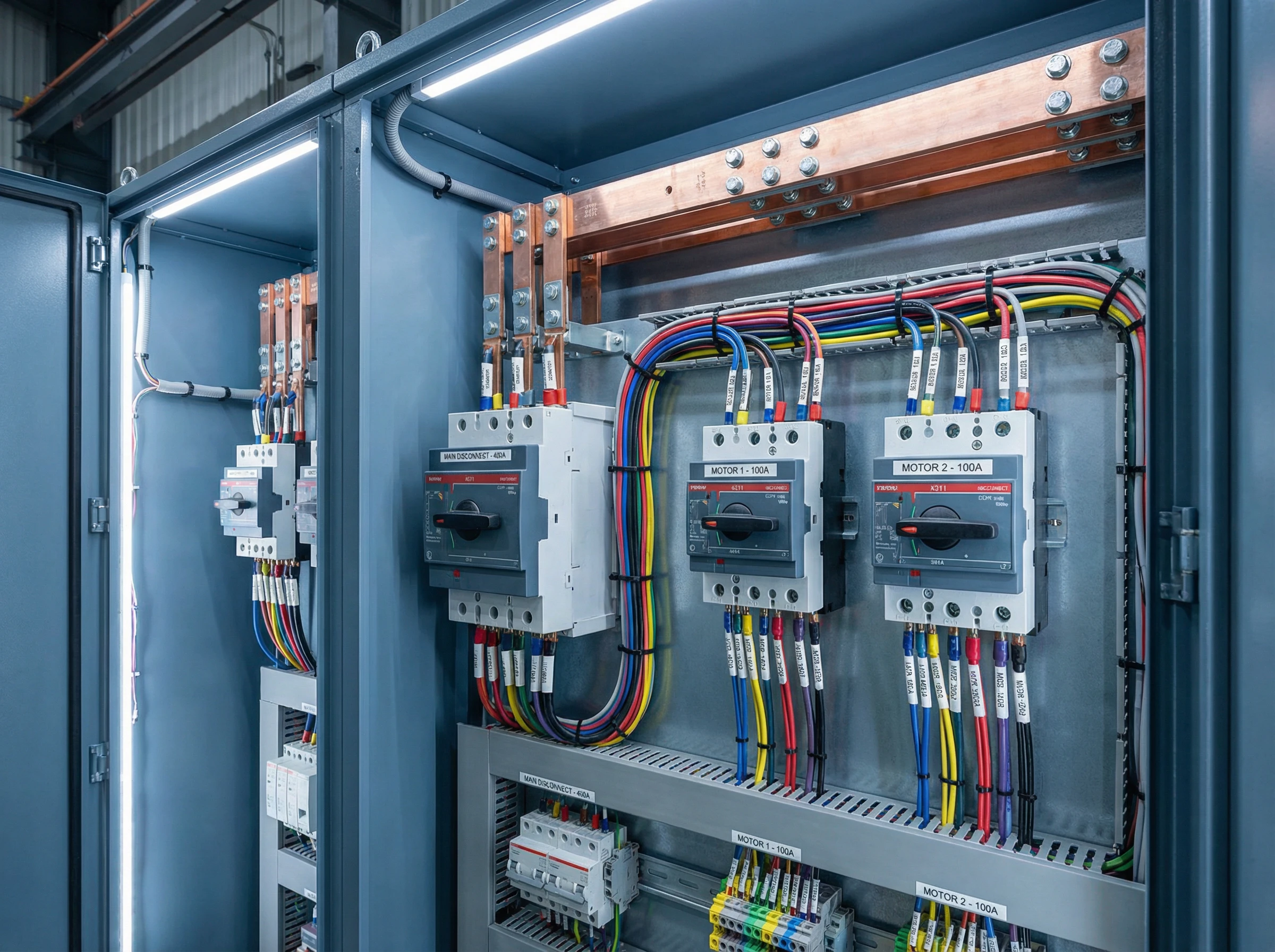
Figure 1: IEC 60947-3 governs switch-disconnectors and their utilization categories (AC-20A, AC-21A, AC-22A, AC-23A), which classify devices by the type of electrical load they’re designed to switch. VIOX Electric manufactures switch-disconnectors engineered to IEC 60947-3 standards.
IEC 60947-3 is the international standard that governs switches, disconnectors, switch-disconnectors, and fuse-combination units used in low-voltage electrical systems (up to 1,000 V AC or 1,500 V DC). Published and maintained by the International Electrotechnical Commission’s Technical Committee 121, this standard establishes performance requirements, testing procedures, and classification systems for mechanical switching devices.
The standard distinguishes between three primary device types:
Switches are mechanical devices capable of making, carrying, and breaking currents under normal operating conditions, including specified overloads. They can carry fault currents for a specified time and may be capable of making (but not breaking) short-circuit currents.
Disconnectors are mechanical devices that, when open, provide an isolating function—creating a visible or verifiable air gap that ensures safe de-energization for maintenance. Disconnectors are not designed to interrupt load currents; they operate only under no-load or negligible-load conditions.
Switch-disconnectors (also called load-break switches) combine both capabilities: they can make, carry, and break currents under normal load conditions while also providing the isolating function when open. This dual capability makes switch-disconnectors the most versatile and commonly specified devices in motor control and distribution applications.
The 2025 consolidated edition (IEC 60947-3:2020+AMD1:2025) introduced significant updates, including conditional short-circuit ratings for devices protected by upstream circuit breakers, critical load current tests for DC applications, and new categories for high-efficiency motors with elevated locked-rotor currents. These updates reflect the evolving demands of modern electrical systems and variable-speed drive technology.
Understanding Utilization Categories
IEC 60947-3 classifies switching devices by utilization category—a designation that defines the type of electrical load the device is designed to switch and the operational duty it must withstand. This classification system recognizes that switching a resistive heater (where current is in phase with voltage and inrush is minimal) imposes vastly different stresses than switching a motor (where locked-rotor currents can reach 6-8 times rated current and power factor is poor during starting).
The utilization category determines the device’s rated operational current (Ie)—the maximum current the device can safely make, carry, and break under its intended duty. Critically, the same physical switch may have different Ie ratings depending on utilization category. For example, a switch-disconnector might be rated for 100A at AC-21A (resistive duty) but only 63A at AC-23A (motor duty) at the same voltage, because motor switching with high inrush demands requires derating.
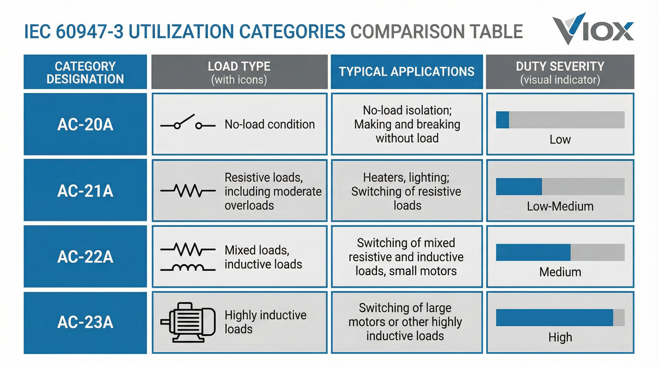
For AC applications, IEC 60947-3 defines four primary categories, designated with an “A” suffix (AC-20A, AC-21A, AC-22A, AC-23A) to distinguish them from DC categories. Understanding these categories is fundamental to proper device selection and reliable system performance.
AC-20A: No-Load Isolation Duty
AC-20A is the lowest-duty utilization category, designed exclusively for isolation switching under no-load or negligible-load conditions. Devices rated for AC-20A are not intended to interrupt significant currents; their primary function is to provide a safe isolating disconnect when circuits are already de-energized or carrying minimal current.
This category typically applies to disconnectors—devices used for sectioning and isolation where load interruption is handled by other equipment (such as contactors or circuit breakers upstream). The AC-20A designation means the device is rated to open and close under conditions where current flow is essentially zero or limited to small capacitive or leakage currents.
Typical AC-20A Applications
- Main isolation switches in distribution boards where the load has been disconnected by other means before operating the isolator
- Sectioning switches for maintenance isolation, providing a visible break for lockout/tagout procedures
- Busbar sectionalizers in switchgear for segmenting distribution systems
- Transfer switch isolation where load transfer is handled by other switching elements
Because AC-20A devices don’t interrupt significant load currents, they can be simpler and more economical than load-break switches. However, it’s critical that operating procedures ensure the circuit is de-energized or de-loaded before operating an AC-20A device. Attempting to break load currents with an AC-20A-rated disconnector can cause contact welding, arcing damage, and safety hazards.
AC-21A: Resistive Load Switching
AC-21A is the utilization category for switching resistive or slightly inductive loads where inrush current is minimal and the current waveform is essentially in phase with the voltage. This category represents straightforward load-break switching without the complications of high inrush or poor power factor.
In AC-21A duty, the making current (the current when closing contacts) is approximately equal to the steady-state load current. There’s no significant inrush surge, and the breaking operation occurs with current and voltage in phase, creating relatively benign arcing conditions. This makes AC-21A the baseline for load-break switching capability.
Typical AC-21A Applications
- Resistive heating loads: Electric furnaces, space heaters, industrial ovens, and process heating elements where the load is purely resistive
- Incandescent lighting circuits: Traditional filament lighting (though LED lighting introduces different characteristics)
- General distribution circuits: Feeders and branch circuits supplying predominantly resistive loads
- Transformer primary switching: Where magnetizing inrush is not a concern (depends on transformer design and switching strategy)
AC-21A Ratings and Performance
Switch-disconnectors rated for AC-21A duty typically offer the highest Ie current rating at a given voltage compared to other categories. For instance, a device might be rated:
- 100A at 400V AC for AC-21A duty
- 80A at 400V AC for AC-22A duty
- 63A at 400V AC for AC-23A duty
The higher AC-21A rating reflects the lower stress imposed by resistive switching. The contacts, arc chambers, and operating mechanisms don’t need to handle the high make currents and poor power factor conditions of inductive loads.
AC-22A: Mixed Resistive and Inductive Loads
AC-22A addresses the middle ground: mixed loads combining both resistive and inductive components, with moderate overload capability required. This category covers distribution circuits and equipment where some inductance is present but motor starting with high locked-rotor currents is not the primary duty.
AC-22A duty recognizes that many real-world loads aren’t purely resistive. Circuits feeding machine tools, industrial equipment, or mixed distribution panels often include transformers, solenoids, small motors, and power supplies alongside resistive elements. The inductive component introduces phase lag between voltage and current, creating more challenging arc extinction conditions compared to AC-21A.
Typical AC-22A Applications
- Mixed distribution feeders: Panelboards or sub-distribution circuits supplying a combination of resistive and inductive loads
- Machine circuits: Industrial machinery with both heating elements and electromagnetic components (coils, solenoids, small motors)
- Lighting circuits with ballasts: Fluorescent or discharge lighting where ballast inductance affects power factor
- Welding equipment: Resistance welders or equipment with significant transformer inductance
- HVAC unit disconnects: Where the load includes both compressor motors and resistive heating (though pure motor duty would be AC-23A)
AC-22A Requirements
The standard requires AC-22A devices to handle moderate overloads and to make and break currents at lower power factors than AC-21A. The making capacity must accommodate brief inrush surges associated with inductive loads, though not to the extent of motor locked-rotor currents.
Manufacturers derate Ie for AC-22A compared to AC-21A at the same voltage, typically by 10-20%, reflecting the increased duty severity. The contacts and arc-quenching systems must handle lagging power factor conditions where current and voltage are out of phase, making arc extinction more difficult.
AC-23A: Motor and Highly Inductive Loads
AC-23A is the most demanding utilization category, designed specifically for switching motors and other highly inductive loads where locked-rotor (starting) currents impose severe make and break stresses. This is the category that matters most in motor control applications, and selecting the wrong category here leads directly to premature switch failure.
When an induction motor starts, it draws locked-rotor current typically 5 to 8 times its full-load rated current, with a power factor as low as 0.3 to 0.5. A switch closing onto a starting motor must make this high inrush current without contact welding or excessive arcing. When breaking motor circuits, the lagging power factor and inductive energy storage create sustained arcs that stress the switching mechanism.
Typical AC-23A Applications
- Direct-on-line (DOL) motor starters: Switch-disconnectors providing both load-break switching and isolation for motor circuits
- Motor feeder disconnects: Main switches upstream of motor control centers or individual motor starters
- Pump and compressor circuits: Direct switching of motor-driven equipment with high starting currents
- Fan and blower controls: Industrial ventilation motors and process air handling equipment
- Conveyor systems: Material handling motors with frequent start-stop cycles
- High-efficiency motor switching (AC-23Ae): A subcategory introduced in recent standards for IE3/IE4 high-efficiency motors that exhibit even higher locked-rotor currents due to optimized electromagnetic design
AC-23A Requirements and Ratings
IEC 60947-3 requires AC-23A devices to handle locked-rotor making currents and to break motor circuits under full-load conditions with poor power factor. The standard specifies test sequences including:
- Making operations at 6-10 times rated current (simulating motor locked-rotor conditions)
- Breaking operations at rated current with inductive loads at specified power factors
- Endurance testing over thousands of operations to verify contact life
As a result, AC-23A ratings are significantly lower than AC-21A ratings for the same device. The 100A switch rated AC-21A at 400V might only be rated 63A for AC-23A duty—a 37% reduction reflecting the severity of motor switching.
AC-23Ae: High-Efficiency Motors
The latest standard edition recognizes AC-23Ae, a specialized subcategory for high-efficiency motors meeting IEC 60034-12 and IEC 60034-30-1 efficiency classes (IE3, IE4). These motors achieve superior efficiency through design changes that inadvertently increase locked-rotor apparent power and starting current. Switches rated AC-23Ae are tested to higher make currents and must handle the elevated inrush demands of modern efficient motor designs.
Key Technical Differences Between Categories
Understanding what distinguishes the utilization categories helps clarify why proper selection matters and what happens when a device is misapplied.
Duty Severity and Current Ratings
The categories represent a progression of increasing duty severity:
- AC-20A: No-load isolation only; not rated for load interruption
- AC-21A: Baseline load-break capability with resistive loads; minimal inrush, in-phase current
- AC-22A: Moderate inductive duty with mixed loads; some phase lag and modest inrush
- AC-23A: Severe motor duty with high locked-rotor inrush and poor power factor at breaking
This severity progression directly determines current ratings. For a typical switch-disconnector at 400V AC:
| Category | Rated Operational Current (Ie) | Relative Rating |
| AC-21A | 100A | 100% (baseline) |
| AC-22A | 80A | 80% |
| AC-23A | 63A | 63% |
The lower ratings for AC-22A and AC-23A aren’t arbitrary derating—they reflect genuine physical limits imposed by inrush handling, arc extinction capability, and contact endurance under demanding conditions.
Making (Closing) Current
Making current is the current that flows when the switch closes onto an energized circuit. This distinguishes categories dramatically:
- AC-20A: Essentially zero making current (no-load)
- AC-21A: Making current ≈ steady-state load current (no significant inrush)
- AC-22A: Making current = 1.5-3× steady-state (moderate inrush from inductance)
- AC-23A: Making current = 6-10× rated current (motor locked-rotor conditions)
AC-23A devices must close contacts onto motor starting currents without welding, requiring robust contact materials, high contact pressure, and arc suppression features that AC-21A devices don’t need.
Breaking (Opening) Current and Power Factor
Breaking imposes different stresses. Resistive loads (AC-21A) present current and voltage in phase; when contacts separate near a natural current zero, the arc extinguishes easily. Inductive loads (AC-22A, AC-23A) present lagging current; the arc sustains longer because current doesn’t cross zero when voltage does.
AC-23A devices must interrupt motor currents at power factors as low as 0.35, creating sustained arcs that require robust arc chutes, blow-out coils, or magnetic arc deflection to force extinction. This is why AC-23A-rated switches have more sophisticated arc management than AC-21A devices.
Operational Endurance
The standard requires different endurance testing by category. AC-23A devices undergo more severe testing with higher make currents and lower power factor breaking, resulting in shorter rated contact life compared to AC-21A at the same physical switch design. Manufacturers publish electrical endurance figures (number of operations at rated current) that decrease from AC-21A to AC-23A.
Applications and Use Cases
Matching utilization categories to real-world applications ensures reliable switching performance and avoids premature device failure.
Industrial Motor Control
Motor control represents the most demanding application and the primary use case for AC-23A devices. In manufacturing facilities, process plants, and industrial infrastructure:
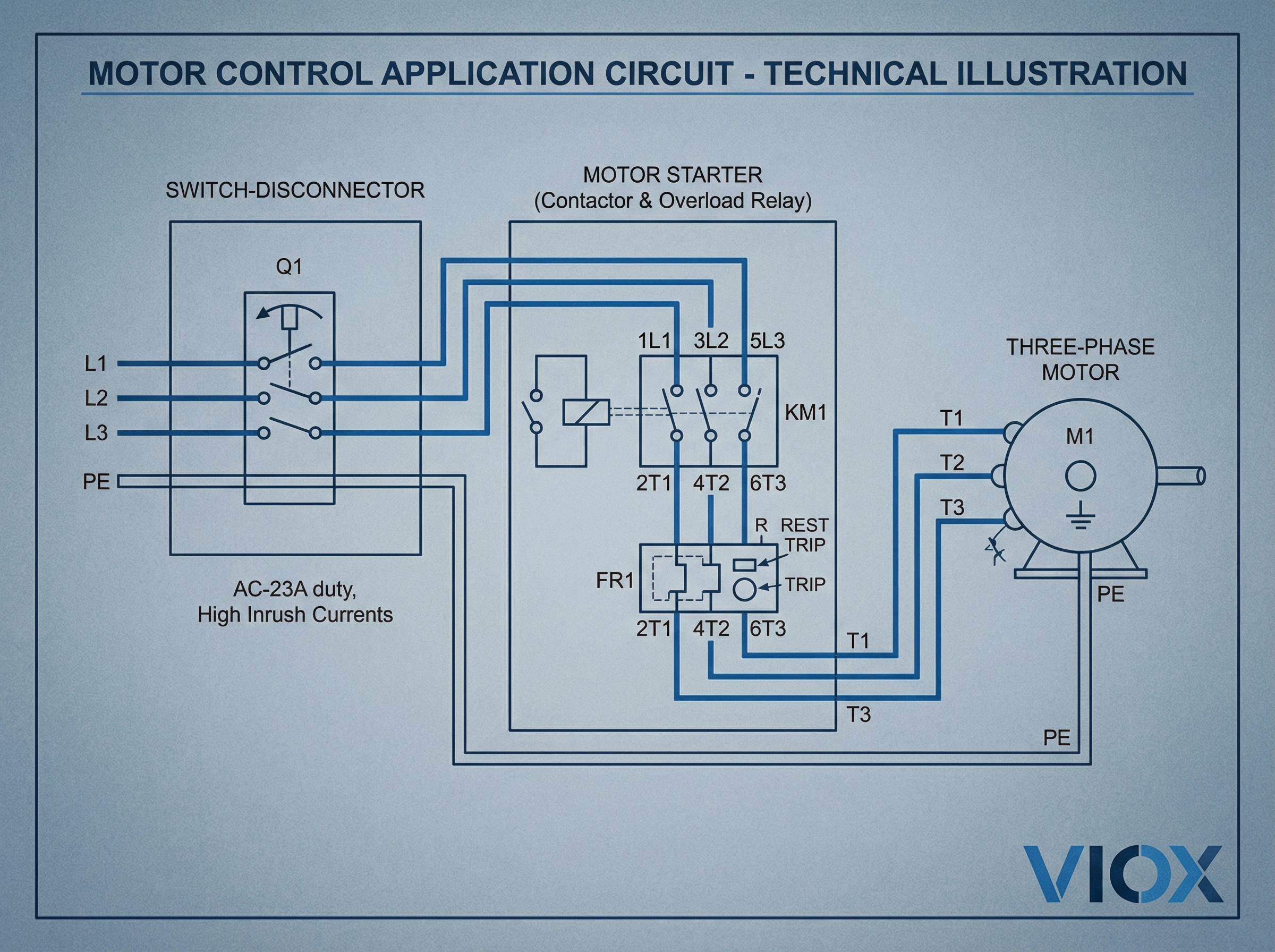
- Motor control centers (MCCs): Switch-disconnectors rated AC-23A serve as main disconnects for individual motor feeders, providing load-break capability and isolation for maintenance. They must handle repeated motor starts with locked-rotor currents 6-8 times full-load.
- Direct-on-line starters: Combined with contactors and overload relays, AC-23A switch-disconnectors enable safe motor starting, stopping, and isolation without requiring separate isolation devices.
- Pump and compressor stations: Motors driving critical infrastructure equipment where reliable switching under inductive load is essential.
- Variable frequency drive (VFD) input disconnects: While VFDs soft-start motors, the input disconnect still faces inrush from DC bus charging capacitors and transformer magnetizing, making AC-22A or AC-23A appropriate depending on drive design.
Commercial Building Distribution
Commercial facilities use switch-disconnectors across all categories:
- HVAC equipment disconnects: Rooftop units and air handlers with compressor motors require AC-23A rating. Pure air handling fans might use AC-22A if inrush is moderate.
- Lighting panel main disconnects: AC-21A for resistive loads (incandescent, LED without significant inrush); AC-22A for fluorescent or discharge lighting with magnetic ballasts.
- Distribution board main switches: AC-21A or AC-22A depending on the mix of downstream loads. Mixed commercial loads typically warrant AC-22A.
- Emergency power transfer: AC-22A or AC-23A depending on connected loads, as the switch must handle making current when transferring between sources.
Process and Manufacturing Equipment
Industrial machinery presents varied switching duties:
- Machine tool disconnects: AC-22A for machines with mixed spindle motors, solenoids, and control power. AC-23A if large direct-started motors are present.
- Conveyor and material handling: AC-23A for direct-started conveyor motors; AC-22A if using soft-start or VFD control.
- Welding equipment: AC-22A for resistance welders with significant transformer inductance but no motor starting duty.
- Process heaters and ovens: AC-21A for purely resistive heating elements; AC-22A if SCR/thyristor control introduces harmonic content or if transformer coupling is involved.
Misapplication Consequences
Applying the wrong category creates predictable failure modes:
- Using AC-21A for motor duty (AC-23A required): Contacts weld during motor starting due to inadequate make capacity; contacts erode rapidly from sustained arcs during breaking; electrical endurance falls far short of expectations, leading to nuisance failures and unplanned downtime.
- Using AC-20A under load (any load-break category required): Severe arcing damages contacts and enclosure; potential for contact welding, creating a safety hazard; device may fail to provide isolation function after load-break operation.
- Oversizing category unnecessarily: Using AC-23A where AC-21A is sufficient increases cost without benefit, though this is a less critical error than under-specification.
Selection Criteria: Matching Category to Application
Selecting the correct utilization category requires analyzing the load characteristics and operational duty. Follow this systematic approach:
Step 1: Identify Load Type and Characteristics
Determine what the switch will control:
- Isolation only, no load breaking: AC-20A (disconnector function)
- Resistive loads (heaters, incandescent lighting, distribution feeding predominantly resistive equipment): AC-21A
- Mixed resistive and inductive loads (distribution with moderate inductance, mixed machinery, fluorescent lighting): AC-22A
- Motors or highly inductive loads (direct motor starting, pump/compressor/fan motors, high-inrush equipment): AC-23A
- High-efficiency motors (IE3/IE4 motors per IEC 60034-30-1): AC-23Ae if available, otherwise AC-23A with appropriate derating
Step 2: Calculate Required Operational Current
Determine the steady-state load current (full-load current for motors, rated current for resistive loads). For motor applications, also identify:
- Motor full-load current (FLC)
- Locked-rotor current or starting current (typically 6-8× FLC for standard motors)
- Motor power factor at starting and running conditions
The switch’s rated operational current Ie for the selected utilization category must meet or exceed the load’s steady-state current. Do not use AC-21A current ratings for motor loads—you must use the AC-23A rating.
Step 3: Verify Voltage Rating and System Compatibility
Confirm the switch’s rated insulation voltage (Ui) and rated operational voltage (Ue) match the system voltage. Check impulse withstand voltage (Uimp) for the installation category (typically CAT III or CAT IV for fixed installations).
Step 4: Check Making Capacity
For AC-23A applications, verify the switch can handle the motor’s locked-rotor current during closing. Manufacturer datasheets specify making capacity as a multiple of Ie (e.g., “making capacity: 10×Ie for AC-23A”). For a motor with 6×FLC locked-rotor current and FLC = 50A, the locked-rotor current is 300A. An AC-23A switch with Ie ≥ 50A and making capacity ≥10×Ie will safely close onto this motor.
Step 5: Evaluate Operational Frequency
Consider how often the switch operates. High-frequency switching (multiple operations per hour) demands attention to electrical endurance ratings. Manufacturer datasheets publish expected operational life (e.g., “electrical endurance: 8,000 operations at Ie for AC-23A”). If operational frequency exceeds this, consider:
- Derating the switch (operating below full Ie to extend contact life)
- Using contactors for frequent switching, reserving the switch-disconnector for isolation and infrequent main switching
Step 6: Consider Isolation Requirements
If the device must provide isolation (lockout/tagout, maintenance disconnect), specify a switch-disconnector rather than a switch. Verify the device meets disconnector isolation requirements per IEC 60947-3 (visible break or position indication, adequate clearance and creepage distances).
Step 7: Review Coordination and Protection
Ensure the switch coordinates with upstream and downstream protection:
- The switch’s rated conditional short-circuit current (if applicable) must meet or exceed the prospective fault current, assuming upstream circuit breaker or fuse protection
- For motor circuits, confirm compatibility with overload relays and short-circuit protection devices
Common Selection Scenarios
Scenario 1: 15 kW / 400V three-phase motor, FLC = 30A, locked-rotor = 180A (6×FLC)
- Load type: Motor → AC-23A required
- Required Ie: ≥30A at AC-23A, 400V
- Making capacity check: Device must handle 180A make current → Verify 10×Ie ≥180A → Ie = 30A, 10×30 = 300A ✓
- Selection: Switch-disconnector rated Ie ≥30A, AC-23A, 400V, with isolation function
Scenario 2: 50 kW electric resistance heater, 400V three-phase, FLC = 72A
- Load type: Resistive → AC-21A suitable
- Required Ie: ≥72A at AC-21A, 400V
- No significant inrush, making ≈ steady-state
- Selection: Switch-disconnector rated Ie ≥80A, AC-21A, 400V
Scenario 3: Distribution panel feeding mixed loads, 100A rated
- Load type: Mixed commercial/industrial → AC-22A appropriate (unless specific motor feeders, which should be separately switched)
- Required Ie: ≥100A at AC-22A
- Selection: Switch-disconnector rated Ie ≥100A, AC-22A, with isolation
Conclusion
IEC 60947-3 utilization categories—AC-20A, AC-21A, AC-22A, and AC-23A—provide a systematic framework for classifying switching devices by the type of electrical load they’re designed to handle. This classification directly determines device ratings, with the same physical switch offering different operational current (Ie) values depending on category: highest for AC-21A resistive duty, progressively lower for AC-22A mixed loads, and lowest for AC-23A motor duty with severe inrush demands.
For electrical engineers specifying switching devices, panel designers selecting components, and maintenance professionals replacing equipment, understanding utilization categories is essential to reliable system operation. Misapplication—particularly using AC-21A devices on motor loads requiring AC-23A—leads to predictable failures: contact welding from inadequate make capacity, rapid contact erosion from sustained inductive arcs, and shortened operational life.
Proper category selection requires analyzing load characteristics (resistive, mixed, or motor), calculating operational current requirements, verifying making capacity for inrush conditions, and ensuring the device meets isolation requirements where needed. The category designation on manufacturer datasheets isn’t optional information—it defines the switching duty the device has been tested to handle and the conditions under which published ratings apply.
VIOX Electric manufactures switch-disconnectors engineered to IEC 60947-3 standards, with clear utilization category ratings and comprehensive technical documentation. For application guidance, technical specifications, or to discuss your specific switching requirements, contact VIOX’s engineering team.
Select the right utilization category for reliable switching performance. Contact VIOX Electric to discuss your switch-disconnector requirements.
