
Why Heating Methods Matter for Motor Protection
Selecting the right thermal overload relay requires understanding two critical factors: the heating element technology and the reset mechanism. The heating method determines response accuracy and thermal memory characteristics, while the reset mode affects maintenance requirements and operational safety. For three-phase motor applications, bimetallic relays with manual reset provide the most reliable protection for standard industrial loads, whereas eutectic alloy types excel in high-precision applications requiring consistent trip points. This guide examines both factors to help you match relay characteristics to your motor protection requirements.
Key Takeaways
- Bimetallic relays use differential thermal expansion for gradual, predictable tripping—ideal for 90% of industrial motor applications
- Eutectic alloy relays provide precise, repeatable trip points through phase-change technology but require manual reset only
- Manual reset forces operator investigation before restart, preventing repeated damage from unresolved faults
- Automatic reset enables remote operation but risks equipment damage if the overload cause persists
- Trip Class selection (10/20/30) must align with motor thermal capacity and starting characteristics
- Ambient temperature compensation is essential for outdoor installations and variable-temperature environments
Understanding Thermal Overload Relay Heating Technologies
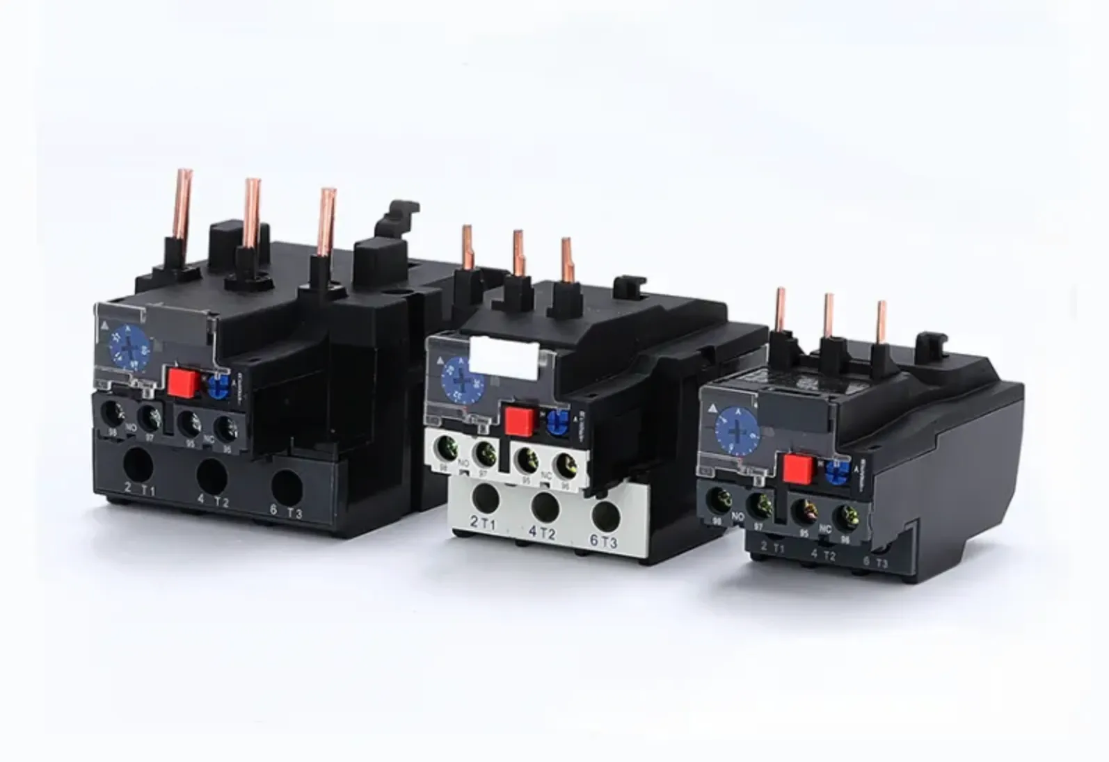
Bimetallic Thermal Overload Relays
Bimetallic thermal overload relays represent the most widely deployed motor protection technology in industrial applications. These devices utilize two dissimilar metals—typically steel paired with a copper-nickel or nickel-chromium alloy—bonded together to form a composite strip. Each metal exhibits a distinct coefficient of thermal expansion, causing the strip to bend predictably when heated by motor current flowing through an adjacent heater element.
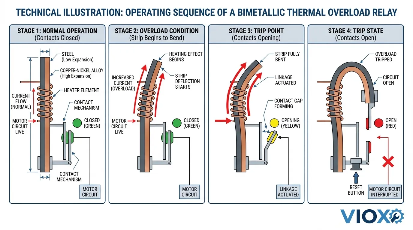
Operating Principle: Current passing through the motor circuit also flows through a calibrated heater coil positioned near the bimetallic strip. As motor load increases, the heater temperature rises proportionally, causing differential expansion between the two metal layers. The strip bends toward the metal with the lower expansion coefficient, eventually actuating a mechanical trip mechanism that opens the control circuit contacts.
Thermal Memory Advantage: Bimetallic relays possess inherent thermal memory—they retain accumulated heat from previous overload events. This characteristic provides superior protection for motors experiencing repeated start-stop cycles or intermittent overloads, as the relay “remembers” the thermal stress and trips faster on subsequent events. The cooling period required before the strip returns to its original shape prevents immediate restart, allowing the motor to dissipate heat safely.
Key Applications:
- General-purpose three-phase motor protection (1-800 HP range)
- Applications with frequent starts and variable loads
- Environments requiring ambient temperature compensation
- Retrofit installations where automatic reset capability is desired
Advantages:
- Cost-effective for most applications
- Available in both manual and automatic reset configurations
- Gradual trip characteristic reduces nuisance tripping during motor startup
- Proven reliability with decades of field performance data
Limitations:
- Trip point accuracy affected by ambient temperature variations (±10-15% typical)
- Mechanical wear over time can affect calibration
- Slower response compared to electronic relays for severe overloads
Eutectic Alloy Thermal Overload Relays
Eutectic alloy overload relays employ a fundamentally different protection mechanism based on phase-change thermodynamics. These devices contain a precisely formulated tin-lead solder alloy sealed within a tube assembly. The alloy composition is engineered to melt at a specific temperature corresponding to the motor’s thermal damage threshold.
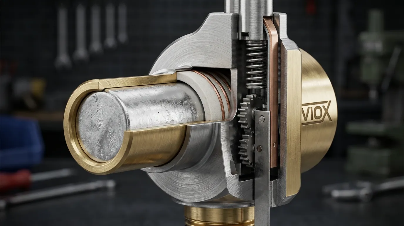
Operating Principle: Motor current flows through a heater winding wrapped around the eutectic alloy tube. Under normal operating conditions, the solid alloy mechanically restrains a spring-loaded ratchet wheel. When sustained overcurrent causes the heater to reach the alloy’s melting point (typically 183°C for standard tin-lead eutectic), the material undergoes rapid liquefaction. This phase change releases the ratchet mechanism, which rotates under spring tension to open the control circuit contacts.
Precision Trip Characteristics: The eutectic alloy’s sharp melting point provides exceptional trip repeatability (±2-3% variation) compared to bimetallic designs. This precision makes eutectic relays the preferred choice for applications where consistent protection thresholds are critical, such as hermetic compressor motors or precision machinery drives.
Reset Requirement: Eutectic relays mandate manual reset—automatic reset is physically impossible because the alloy must cool and resolidify before the ratchet mechanism can be manually re-engaged. This forced intervention ensures that operators investigate the overload cause before restarting equipment.
Key Applications:
- NEMA-rated motor starters (Size 1-6)
- Hermetic refrigeration compressor protection
- Critical process motors requiring precise trip points
- Applications where manual reset verification is mandatory
Advantages:
- Superior trip point accuracy and repeatability
- Unaffected by mechanical vibration
- Excellent long-term calibration stability
- Inherent manual reset provides safety verification
Limitations:
- Manual reset only—no remote restart capability
- Higher initial cost compared to bimetallic types
- Longer cooling period required before reset (5-15 minutes typical)
- Limited availability for smaller motor ratings
Comparative Analysis: Bimetallic vs. Eutectic Technology
| Characteristic | Bimetallic Relay | Eutectic Alloy Relay |
|---|---|---|
| Trip Mechanism | Differential thermal expansion | Phase-change liquefaction |
| Trip Accuracy | ±10-15% (temperature dependent) | ±2-3% (highly repeatable) |
| Reset Options | Manual or automatic | Manual only |
| Thermal Memory | Excellent (gradual cooling) | Moderate (binary solid/liquid state) |
| Response Speed | Gradual (Class 10/20/30 selectable) | Rapid at trip point |
| Ambient Compensation | Available in premium models | Inherent due to fixed melting point |
| Typical Cost | Lower | 20-40% higher |
| Maintenance | Periodic calibration recommended | Minimal—inherently stable |
| Best Applications | General industrial motors, variable loads | Precision applications, hermetic motors |
Reset Mode Selection: Manual vs. Automatic
The reset mechanism determines how a thermal overload relay returns to normal operation after a trip event. This choice significantly impacts operational safety, maintenance requirements, and system automation capabilities.
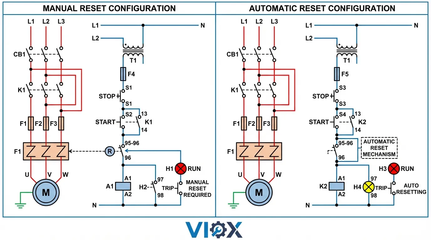
Manual Reset Configuration
Manual reset relays require physical operator intervention to restore the circuit after a trip. A reset button or lever on the relay housing must be pressed or rotated to mechanically re-engage the contact mechanism. This design enforces a mandatory investigation period before equipment restart.
Safety Advantages: Manual reset provides a critical safety checkpoint. When a motor trips on overload, the forced manual intervention ensures that:
- Operators physically inspect the motor and driven equipment for mechanical faults
- Overload causes (jammed bearings, excessive load, phase imbalance) are identified and corrected
- Cooling time is sufficient before restart attempts
- Documentation of trip events occurs for maintenance trending
Ideal Applications:
- Critical safety systems where unattended restart poses hazards
- Motors driving equipment that could be damaged by unexpected restart (conveyors, mixers, crushers)
- Installations with limited remote monitoring capability
- Applications subject to OSHA lockout/tagout requirements
- Hermetic compressors requiring cooling verification before restart
Limitations:
- Requires local access to relay location
- Increases downtime in remote or difficult-to-reach installations
- Not suitable for fully automated processes requiring unattended operation
- May require additional personnel for 24/7 operations
Automatic Reset Configuration
Automatic reset relays self-restore once the thermal element cools below the reset threshold. The contact mechanism re-engages without operator intervention, allowing the motor starter to re-energize when control power is restored.
Operational Advantages: Automatic reset enables:
- Remote system restart via PLC or SCADA control
- Reduced downtime for transient overload events
- Unmanned operation in remote installations (pump stations, HVAC systems)
- Simplified integration with building automation systems
Critical Considerations:
- Repeated Restart Cycles: If the overload cause persists, automatic reset allows repeated motor starts that can rapidly overheat windings beyond thermal damage limits
- Unexpected Equipment Motion: Automatic restart can create hazards if personnel are working near machinery assuming it is disabled
- Masked Failure Modes: Transient trips may reset before operators notice, hiding developing mechanical or electrical problems
- Compressor Damage Risk: Refrigeration systems may restart before refrigerant pressure equalizes, causing compressor failure
Reset Mode Selection Matrix
| Application Type | Recommended Reset Mode | Justification |
|---|---|---|
| Conveyor systems | Manual | Prevents restart with jammed material or personnel near equipment |
| Submersible pumps (remote) | Automatic | Enables remote restart; monitor via SCADA for repeated trips |
| Machine tool drives | Manual | Ensures investigation of mechanical binding or tool breakage |
| HVAC air handlers | Automatic | Transient overloads common; building automation integration required |
| Hermetic compressors | Manual | Mandatory cooling period; prevents short-cycle damage |
| Irrigation pumps | Automatic | Remote locations; acceptable transient overload during startup |
| Mixer/agitator drives | Manual | Prevents restart with solidified material or mechanical failure |
| Packaged rooftop units | Automatic | Integrated controls; remote monitoring via BMS |
Trip Class Selection for Motor Thermal Protection
Trip class defines the maximum time a thermal overload relay permits sustained overcurrent before interrupting the circuit. This standardized classification, defined by IEC 60947-4-1 and UL standards, ensures relay response characteristics match motor thermal capacity and starting profiles.
Understanding Trip Class Standards
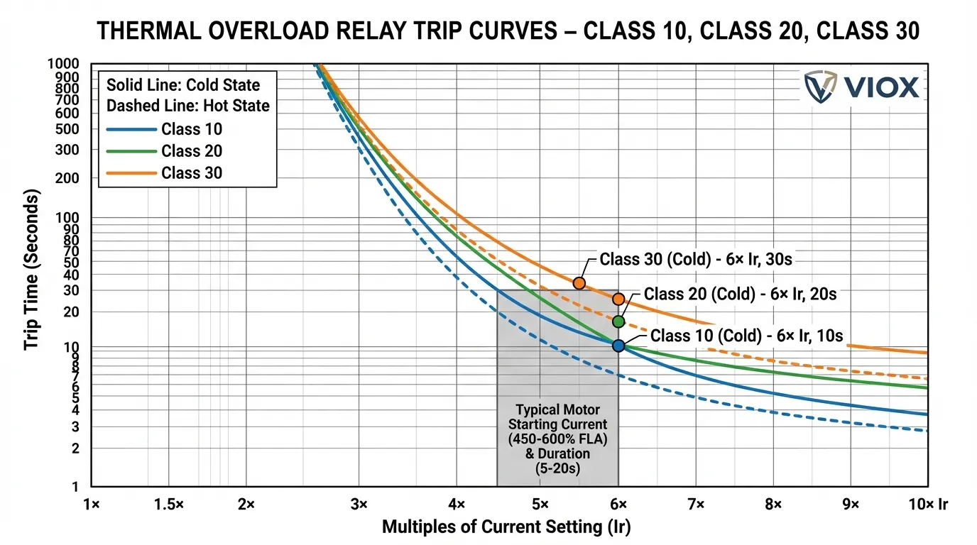
Trip class is expressed as a number (5, 10, 20, or 30) representing the maximum trip time in seconds when the relay carries 600% of its current setting from a cold start. This standardized test condition provides a consistent basis for comparing relay response across manufacturers.
| Trip Class | Trip Time at 600% Current | Typical Applications |
|---|---|---|
| Class 5 | 5 seconds maximum | Submersible pumps, hermetic compressors (limited thermal mass) |
| Class 10 | 10 seconds maximum | IEC motors, quick-start applications, artificially cooled motors |
| Class 20 | 20 seconds maximum | NEMA design B motors, general industrial applications (most common) |
| Class 30 | 30 seconds maximum | High-inertia loads, mill-duty motors, extended acceleration times |
Cold State vs. Hot State Trip Curves
Thermal overload relays exhibit significantly different response characteristics depending on their initial thermal condition:
Cold State Operation: When a motor starts after sufficient cooling time (typically 2+ hours at ambient temperature), the thermal element begins from room temperature. The relay requires maximum time to accumulate heat and reach the trip threshold. Published trip curves typically represent cold-state performance.
Hot State Operation: Motors that cycle frequently or restart shortly after stopping begin with elevated thermal element temperatures. Hot-state trip curves show 20-30% faster response times because the relay starts closer to the trip threshold. This accelerated response provides critical protection for motors experiencing repeated overload events without adequate cooling periods.
Practical Implications:
- Frequent start-stop applications must consider hot-state curves to avoid nuisance tripping
- Motors with duty cycles exceeding 60% operate predominantly in hot-state conditions
- Temperature-compensated relays adjust trip characteristics based on ambient temperature to maintain consistent protection
Application-Specific Trip Class Selection
Class 10 Selection Criteria:
- Motors with limited thermal capacity (submersible pumps, close-coupled designs)
- Quick-start applications where acceleration completes within 3-5 seconds
- IEC-rated motors designed for faster protection response
- Applications where motor damage occurs rapidly during locked-rotor conditions
Example: A 15 HP submersible well pump motor with Class B insulation operates submerged in 50°F water. The external cooling allows aggressive Class 10 protection without nuisance tripping during normal starts, while providing rapid response if the pump runs dry or encounters mechanical binding.
Class 20 Selection Criteria (Most Common):
- NEMA Design B motors with standard thermal capacity
- General industrial applications with 5-10 second acceleration times
- Loads with moderate starting torque requirements
- Applications where occasional transient overloads are acceptable
Example: A 50 HP motor driving a centrifugal fan in an HVAC system experiences 5-7 second acceleration with 450% starting current. Class 20 protection accommodates normal startup while tripping within 20 seconds if the fan becomes mechanically bound or experiences bearing failure.
Class 30 Selection Criteria:
- High-inertia loads requiring extended acceleration (15-25 seconds)
- Mill-duty or severe-duty motors with enhanced thermal capacity
- Applications with high breakaway torque (crushers, ball mills, extruders)
- Loads where startup current exceeds 500% FLA for extended periods
Example: A 200 HP motor driving a ball mill requires 18-22 seconds to reach full speed due to the massive rotating mass. The mill’s charge weight creates 550% starting current throughout acceleration. Class 30 protection prevents nuisance tripping during normal starts while still protecting against locked-rotor or mechanical jam conditions.
Common Trip Class Selection Errors
Oversizing for Nuisance Trip Avoidance: Selecting Class 30 protection for a standard motor experiencing nuisance trips masks underlying problems (mechanical binding, voltage issues, improper relay sizing) rather than addressing root causes. This practice exposes motors to thermal damage during genuine overload events.
Undersizing for “Better Protection”: Specifying Class 10 relays for high-inertia loads causes repeated nuisance trips during normal acceleration. This leads to operators defeating protection systems or oversizing relay settings—both practices that eliminate effective motor protection.
Ignoring Hot-State Curves: Applications with frequent cycling must evaluate hot-state trip characteristics. A motor that successfully starts cold may experience nuisance trips after several rapid cycles due to accumulated thermal element heat.
Ambient Temperature Compensation
Thermal overload relays are calibrated for optimal performance at 40°C (104°F) ambient temperature per IEC standards. Significant deviations from this reference point affect trip accuracy and response time, potentially compromising motor protection or causing nuisance trips.
Temperature Effects on Relay Performance
High Ambient Temperatures (>40°C):
- Thermal elements start closer to trip threshold
- Trip times decrease by 10-20% at 50°C ambient
- Risk of nuisance tripping during normal motor operation
- Effective current setting reduced (relay trips at lower actual current)
Low Ambient Temperatures (<20°C):
- Thermal elements require more heat accumulation to trip
- Trip times increase by 15-25% at 0°C ambient
- Risk of inadequate motor protection during genuine overloads
- Effective current setting increased (relay may not trip until motor damage occurs)
Compensation Technologies
Bimetallic Compensation: Premium bimetallic relays incorporate additional compensating bimetal elements that counteract ambient temperature effects. These elements adjust the trip mechanism position based on surrounding temperature, maintaining consistent trip characteristics across -25°C to +60°C operating ranges.
Electronic Temperature Sensing: Modern electronic overload relays use thermistor or RTD sensors to measure ambient temperature and algorithmically adjust trip thresholds. This active compensation provides ±3% accuracy across wide temperature ranges and enables advanced features like motor thermal modeling.
Application Guidelines
Outdoor Installations: Motors in outdoor enclosures experience ambient temperatures ranging from -20°C to +50°C depending on climate and solar loading. Temperature-compensated relays are mandatory for consistent protection across seasonal variations.
High-Temperature Environments: Foundries, steel mills, and other high-temperature industrial settings require relays rated for continuous operation at 60°C ambient with appropriate derating of current settings or selection of high-temperature models.
Cold Storage Applications: Refrigerated warehouses and cold storage facilities operating at -20°C to 0°C require low-temperature-rated relays with compensation to prevent delayed tripping during motor overloads.
Practical Selection Workflow
Step 1: Determine Motor Thermal Characteristics
Gather the following motor nameplate and application data:
- Full Load Amps (FLA) from motor nameplate
- Service Factor (SF)—typically 1.0 or 1.15 for industrial motors
- Insulation class (B, F, or H) indicating thermal capacity
- Duty cycle and expected starts per hour
- Acceleration time under full load conditions
Step 2: Select Heating Technology
Choose Bimetallic If:
- General industrial motor protection (1-800 HP)
- Automatic reset capability desired for remote operation
- Budget constraints favor lower initial cost
- Application involves variable loads or frequent cycling
Choose Eutectic Alloy If:
- Precise, repeatable trip points required
- NEMA-rated starter integration (Size 1-6)
- Hermetic compressor or critical process motor
- Manual reset verification mandatory for safety compliance
Step 3: Determine Trip Class
Select Class 10 If:
- Motor acceleration time <5 seconds
- IEC-rated motor or submersible pump application
- Limited motor thermal capacity requires fast protection
- Quick-start application with low inertia load
Select Class 20 If (Default Choice):
- NEMA Design B motor with standard thermal capacity
- Acceleration time 5-10 seconds
- General industrial application without special requirements
- Motor manufacturer does not specify alternative class
Select Class 30 If:
- High-inertia load with acceleration time >15 seconds
- Mill-duty or severe-duty motor rating
- Motor manufacturer specifically recommends Class 30
- Documented nuisance tripping with Class 20 during normal starts
Step 4: Choose Reset Mode
Select Manual Reset If:
- Safety regulations require operator verification before restart
- Equipment could be damaged by unexpected restart
- Local access to relay location is practical
- Application involves lockout/tagout procedures
Select Automatic Reset If:
- Remote installation requires unattended operation
- SCADA or BMS integration needed for automated restart
- Transient overloads are expected and acceptable
- Comprehensive remote monitoring and alarming implemented
Step 5: Consider Environmental Factors
Temperature Compensation Required If:
- Ambient temperature varies >±10°C from 40°C reference
- Outdoor installation subject to seasonal temperature extremes
- High-temperature environment (foundries, steel mills)
- Cold storage or refrigerated space installation
Additional Environmental Considerations:
- Corrosive atmospheres require sealed relay enclosures
- High-vibration environments favor eutectic alloy technology
- Dusty conditions require NEMA 12 or IP54 minimum enclosure rating
Integration with Motor Protection Systems
Thermal overload relays function as part of a comprehensive motor protection strategy. Understanding their role within the broader protection architecture ensures effective coordination and prevents protection gaps.
Coordination with Upstream Protective Devices
Circuit Breaker Coordination: The upstream circuit breaker or motor circuit protector (MCP) must provide short-circuit protection without interfering with overload relay operation. Proper coordination ensures:
- Circuit breaker instantaneous trip set above motor locked-rotor current (typically 10-12× FLA)
- Overload relay provides all protection for 115-600% FLA range
- No overlap or gap in protection coverage across current ranges
Fuse Coordination: When fuses provide short-circuit protection, select Class RK1 or Class J fuses with time-delay characteristics that permit motor starting current without opening. Coordination curves should show clear separation between fuse minimum melt time and overload relay maximum trip time.
Integration with Contactors
Thermal overload relays mount directly to contactors in IEC configurations or install separately in NEMA assemblies. The overload relay’s auxiliary contacts connect in series with the contactor coil circuit, ensuring that any overload trip de-energizes the contactor and interrupts motor power.
Critical Wiring Considerations:
- Overload relay auxiliary contacts rated for control circuit voltage and current
- Proper phasing ensures all three motor phases monitored (three-pole relays)
- Heater elements sized for actual motor FLA, not circuit breaker rating
- Control circuit includes overload reset status indication
For detailed guidance on contactor selection and motor control fundamentals, see our comprehensive guide on what contactors are and how they work.
Advanced Protection Features
Modern electronic overload relays offer enhanced protection capabilities beyond basic thermal modeling:
Ground Fault Protection: Detects current imbalance between phases indicating ground fault conditions. Particularly critical for personnel safety in wet or conductive environments.
Phase Loss/Imbalance Protection: Monitors all three phases and trips if voltage or current imbalance exceeds 10-15%. Prevents single-phasing damage to three-phase motors.
Locked Rotor Protection: Provides faster trip response when motor fails to accelerate, preventing winding damage during mechanical jam conditions.
Motor Thermal Modeling: Electronic relays calculate accumulated motor heat based on current history, duty cycle, and cooling time. This sophisticated algorithm provides superior protection compared to simple thermal element response.
For foundational understanding of thermal overload relay operation and components, refer to our detailed article on thermal overload relay basics.
Installation and Commissioning Best Practices
Proper Relay Sizing and Setting
Current Setting Procedure:
- Locate motor nameplate Full Load Amps (FLA)
- For motors with 1.15 Service Factor: Set relay to motor FLA
- For motors with 1.0 Service Factor: Set relay to 90% of motor FLA
- Verify setting accounts for any current unbalance in three-phase systems
Common Sizing Errors:
- Setting relay to circuit breaker rating instead of motor FLA
- Failing to account for service factor in setting calculation
- Oversizing relay setting to prevent nuisance trips rather than addressing root causes
- Using single-phase relay current rating for three-phase motor applications
Mounting and Environmental Considerations
Orientation Requirements: Most thermal overload relays are calibrated for vertical mounting position (±30° from vertical). Horizontal mounting can affect trip accuracy by 10-15% due to gravity effects on mechanical trip mechanisms. Consult manufacturer specifications for approved mounting orientations.
Enclosure Selection:
- Indoor, clean environments: NEMA 1 / IP20 minimum
- Outdoor or dusty locations: NEMA 3R or 4 / IP54 or IP65
- Corrosive atmospheres: NEMA 4X stainless steel / IP66
- Hazardous locations: Explosion-proof enclosures per NEC Article 500
Ventilation Requirements: Ensure adequate air circulation around thermal relays. Enclosed starters in hot environments may require forced ventilation or oversized enclosures to prevent ambient temperature from affecting relay performance.
Testing and Verification
Initial Commissioning Tests:
- Continuity Test: Verify auxiliary contact operation through manual test button
- Current Setting Verification: Confirm dial or digital setting matches motor FLA
- Trip Class Confirmation: Verify relay trip class matches motor requirements
- Reset Function Test: Confirm manual or automatic reset operates correctly
- Phase Balance Check: Measure current on all three phases under full load
Periodic Maintenance Testing:
- Annual trip time verification using primary current injection (600% FLA test)
- Contact resistance measurement on auxiliary contacts
- Visual inspection for signs of overheating, corrosion, or mechanical damage
- Calibration verification for adjustable relays (compare to manufacturer specifications)
Troubleshooting Common Issues
Nuisance Tripping
| Symptom | Probable Cause | Diagnostic Procedure | Solution |
|---|---|---|---|
| Trips during motor startup | Trip class too fast for application | Measure acceleration time; compare to relay trip curve | Upgrade to slower trip class (10→20 or 20→30) |
| Trips after several rapid starts | Insufficient cooling between starts | Monitor duty cycle; check hot-state trip curve | Reduce start frequency or select relay with better thermal memory |
| Trips in hot weather only | Ambient temperature compensation inadequate | Measure enclosure temperature during trip events | Install temperature-compensated relay or improve ventilation |
| Random trips under normal load | Loose heater element connections | Inspect heater element terminals; measure voltage drop | Tighten connections; replace damaged heaters |
| Trips on one phase only | Phase imbalance or single heater failure | Measure current on all three phases | Balance load; replace faulty heater element |
Failure to Trip During Overload
Critical Safety Issue: A relay that fails to trip during genuine overload conditions exposes the motor to thermal damage and potential fire hazards. Immediate investigation required.
Diagnostic Steps:
- Verify relay current setting matches motor FLA (not oversized)
- Test relay trip function using manual test button
- Measure actual motor current under load conditions
- Compare measured current to relay setting and trip curve
- Perform primary injection test at 150% and 200% of relay setting
Common Causes:
- Relay setting inadvertently increased to prevent nuisance trips
- Heater elements damaged or incorrect size installed
- Mechanical trip mechanism binding or worn
- Automatic reset relay repeatedly resetting before operator notices trips
Frequently Asked Questions
Q: Can I use a Class 20 thermal overload relay with a Class 10 motor?
A: No. Using a slower trip class than the motor requires exposes the motor to thermal damage during overload conditions. The motor manufacturer specifies the required trip class based on the motor’s thermal capacity and cooling design. Always match or exceed (faster) the motor’s specified trip class requirement. If experiencing nuisance trips with the correct trip class, investigate the root cause (mechanical binding, voltage issues, improper sizing) rather than selecting a slower relay.
Q: How do I know if my application needs ambient temperature compensation?
A: Temperature compensation is essential when ambient temperature varies more than ±10°C from the 40°C calibration standard. Calculate the expected temperature range at the relay location, considering seasonal variations, solar loading on outdoor enclosures, and heat from adjacent equipment. Applications requiring compensation include outdoor installations, high-temperature industrial environments (>50°C), and cold storage facilities (<20°C). Modern electronic overload relays include automatic temperature compensation as a standard feature.
Q: What’s the difference between thermal overload relays and motor circuit protectors?
A: Thermal overload relays provide time-delayed protection against sustained overcurrent conditions (115-600% FLA range), allowing motors to start normally while protecting against overload damage. Motor circuit protectors (MCPs) are specialized circuit breakers providing instantaneous short-circuit protection (typically >10× FLA) without time delay. Complete motor protection requires both devices: MCPs for short-circuit protection and thermal overload relays for overload protection. Some modern motor protection circuit breakers (MPCBs) combine both functions in a single device.
Q: Can I replace eutectic alloy thermal units with bimetallic elements?
A: No. Eutectic alloy and bimetallic relays have different mounting configurations, heater element specifications, and trip characteristics. The relay base and contactor are designed for a specific thermal element type. Mixing technologies will result in improper fit, incorrect trip characteristics, and loss of motor protection. When replacing thermal elements, always use the exact manufacturer part number specified for your relay model. Cross-referencing between manufacturers requires careful verification of electrical ratings and trip curves.
Q: Why does my automatic reset relay keep cycling on and off?
A: Repeated automatic reset cycling indicates the overload condition has not been resolved. The relay trips, cools, resets, and immediately trips again because the motor continues drawing excessive current. This cycling can rapidly overheat motor windings beyond thermal damage limits. Immediate actions required: (1) Switch to manual reset mode or install a lockout device to prevent further cycling, (2) Investigate the overload cause—check for mechanical binding, excessive load, phase imbalance, or voltage problems, (3) Measure actual motor current under load and compare to nameplate FLA, (4) Verify relay setting matches motor requirements. Never increase the relay setting to stop cycling without identifying and correcting the root cause.
Conclusion
Selecting the appropriate thermal overload relay requires balancing heating technology, reset mode, trip class, and environmental factors against your specific motor protection requirements. Bimetallic relays offer versatile, cost-effective protection for most industrial applications, while eutectic alloy types provide precision trip characteristics for critical processes. Manual reset enforces safety verification but limits automation, whereas automatic reset enables remote operation with careful monitoring protocols.
The trip class selection directly impacts nuisance tripping frequency and motor protection effectiveness—Class 20 serves as the default for NEMA motors, with Class 10 or 30 specified only when motor thermal characteristics or load profiles demand faster or slower response. Ambient temperature compensation becomes essential for installations experiencing significant temperature variations.
For comprehensive motor protection system design, integrate thermal overload relays with properly coordinated upstream short-circuit protection and consider advanced electronic relays for applications requiring ground fault detection, phase monitoring, or sophisticated thermal modeling capabilities. Regular testing and maintenance ensure continued protection reliability throughout the relay’s service life.
