
Introduction
When designing photovoltaic installations, few decisions carry as much long-term impact as properly sizing your solar combiner box. This critical junction point collects multiple PV strings into a single, higher-current output—and undersizing it today can force expensive equipment replacement when you’re ready to expand tomorrow. According to field data from commercial solar contractors, nearly 40% of expansion projects face delays or cost overruns because the original combiner box lacked adequate capacity for additional strings.
The good news: with systematic planning and proper application of NEC Article 690 requirements, you can size a solar combiner box that accommodates both your current installation and future string additions without over-engineering or wasting budget. This guide walks through a proven, step-by-step methodology that balances immediate specifications with expansion flexibility—ensuring your PV system can grow efficiently from 12 strings to 20 or beyond without reworking the entire DC architecture.
Understanding Expansion Requirements
Before calculating wire sizes or selecting enclosures, you need a clear picture of how your PV array might grow. Commercial and utility-scale solar projects frequently deploy in phases—installing 60% of planned capacity in year one and reserving land, interconnection allocation, and electrical infrastructure for future build-outs. Residential rooftop installations also expand when homeowners add electric vehicles or battery storage, creating demand for additional string circuits.
Effective expansion planning starts with realistic forecasting. Ask: Will you add strings within 12 months, or is this a five-year horizon? Are future modules the same electrical specifications, or will you adopt higher-current bifacial panels? Understanding these drivers determines whether you need two extra input positions or eight, and whether your branch current ratings must accommodate today’s 10A strings or tomorrow’s 15A modules. Financial modeling often reveals that buying a combiner with 20–24 positions today—even if you only populate 12—costs far less than replacing an undersized unit mid-project, avoiding downtime, labor, and permit revisions.
Key Sizing Parameters for Solar Combiner Box
Successful combiner sizing depends on four fundamental electrical and mechanical parameters. Each must be calculated for both your present installation and anticipated expansion to ensure code compliance and safe operation.
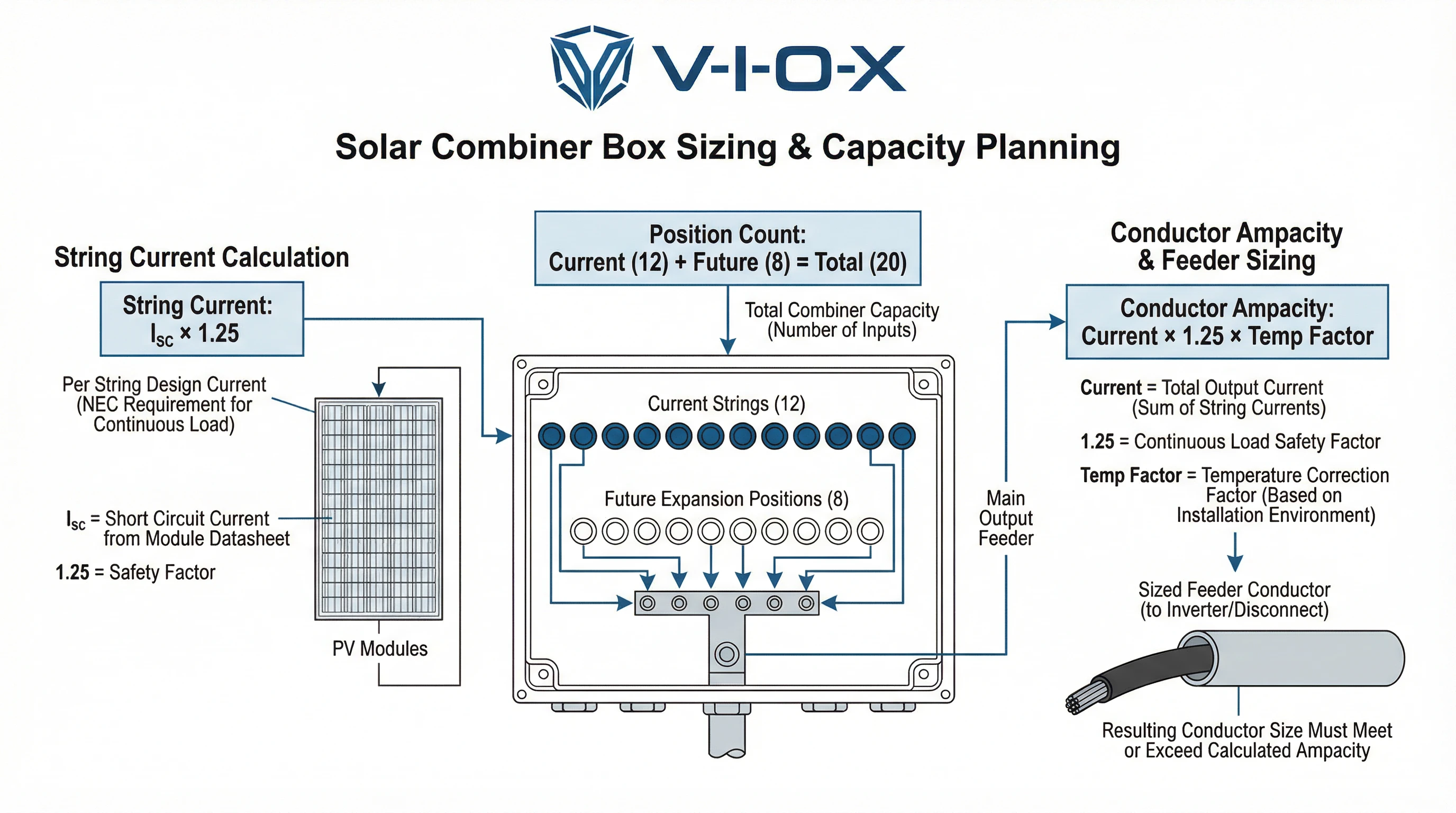
Maximum String Current (Isc × 1.25): Under NEC 690.8(A), you must size circuits to handle the module’s short-circuit current (Isc) multiplied by 1.25 to account for irradiance variation. For example, a module rated at 11A Isc produces a maximum circuit current of 13.75A. This factor applies to every string, and the combined total determines your combiner’s output busbar requirements.
Number of Input Positions: This is the count of physical terminals or fuse holders inside the solar combiner box—one per string. If you’re installing 12 strings today but plan to reach 18 within three years, specify at least 18 positions. Many manufacturers offer modular product lines (16/18/20/24 inputs) in the same enclosure footprint, making future population straightforward without wholesale replacement.
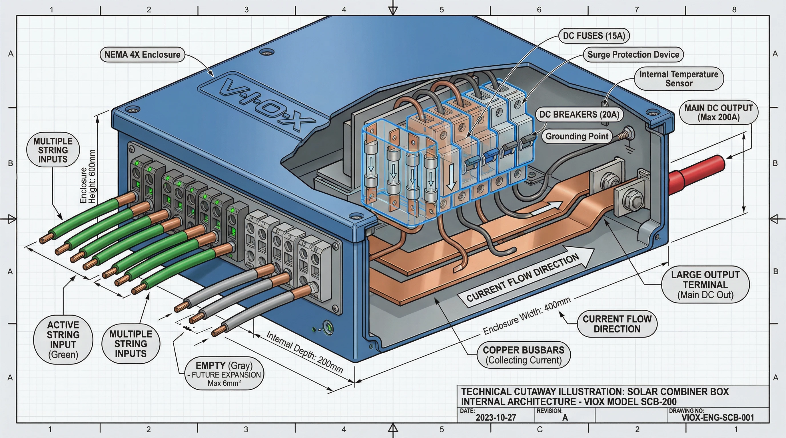
Busbar and Terminal Ampacity: Busbars collect the paralleled string currents and feed the PV output circuit. Under NEC 690.8(B), you must size conductors to at least 125% of the maximum continuous current, then apply temperature and installation derating factors. A combiner supporting 12 strings at 13.75A each produces 165A combined, requiring conductor ampacity around 206A before environmental corrections.
Enclosure Thermal Capacity: Solar combiner boxes operate outdoors, often in direct sunlight with ambient temperatures exceeding 40°C. Adequate ventilation, thermal dissipation design, and proper IP ratings (IP65 or IP67) prevent internal overheating that degrades terminals and accelerates component failure. When planning for expansion, confirm the enclosure can handle increased I²R losses as string count grows.
Step 1: Calculate Current System Requirements
Start by establishing the baseline electrical characteristics of your existing or initial PV array. This forms the foundation for all subsequent expansion calculations.
Determine Maximum Circuit Voltage (Vmax): Using NEC 690.7, calculate Vmax as the module’s open-circuit voltage (Voc) multiplied by the number of series modules and the temperature correction factor for your coldest expected ambient. For example, 12 modules at 50V Voc in a cold climate (factor 1.12) yields 672 Vdc. Select a combiner voltage rating that exceeds this value—typically 1000 Vdc for commercial installations or 1500 Vdc for utility-scale projects.
Calculate String Current: Take the module datasheet Isc and apply the 1.25 multiplier per NEC 690.8(A). If your modules are rated 11A Isc, your maximum string current is 13.75A. This value dictates the minimum rating for string-level overcurrent protection devices (fuses or breakers) and the branch current capacity of your combiner.
Count Required Input Positions: For a 12-string array, you need 12 input terminals. However, stop here—this is only the starting point. Document these present-day values as your sizing baseline: The string count is 12, with module specification Isc at 11A. Maximum string current calculates to 13.75A (11A × 1.25), producing a combined array current of 165A (12 × 13.75A). Continuous conductor sizing requirements reach 206A (165A × 1.25 per NEC 690.8(B)).
These figures represent what you need today, but not what you should specify for a future-ready solar combiner box.
Step 2: Forecast Future String Additions
Now project your PV system’s realistic growth trajectory. This step requires balancing technical capacity against business planning and site constraints.
Identify Growth Drivers: Common expansion triggers include phased project financing, available roof or land area, future load increases (EV charging, heat pumps), and battery storage integration. Utility-scale projects often plan 2–3 build phases over five years, while commercial rooftops might reserve capacity for a single 30–40% expansion within two years.
Establish String Count Targets: Based on your growth drivers, determine the maximum credible string count. If you’re installing 12 strings in phase one and your site can accommodate 20 total, plan for 20 positions. Avoid over-specifying to 40 strings unless your interconnection agreement and land permit support it—excess capacity costs money and complicates equipment selection.
Assess Module Technology Trends: Future strings might use different modules. Today’s 10–11A Isc panels are giving way to bifacial, large-format cells with 13–15A ratings. If you expect to mix module generations, use the higher current rating when sizing branch capacity and OCPDs. A combiner rated for 15A branches today will accept both your current 11A strings and future 14A additions without modification.
Document your expansion forecast clearly: “Current: 12 strings at 11A Isc. Target: 20 strings, allowing up to 15A Isc per string.” This becomes your specification anchor.
Step 3: Apply Derating and Safety Factors
Raw calculations aren’t enough—code compliance and safe long-term operation demand systematic derating. This step transforms your forecast into defensible specifications.
NEC 690.8 Continuous Current Requirements: The National Electrical Code mandates that PV conductors and overcurrent devices handle 125% of maximum circuit current. This accounts for continuous daytime operation under peak irradiance. For 20 strings at 15A Isc each, your maximum combined current is 20 × 15A × 1.25 = 375A. Conductor ampacity must then reach 375A × 1.25 = 469A before temperature corrections—this double application of 125% (once for irradiance, once for continuous duty) is critical and frequently missed.
Temperature Derating Factors: Outdoor combiner enclosures experience significant solar heating. NEC Table 310.15(B)(1) provides ampacity correction factors for ambient temperatures above 30°C. In hot climates where enclosures reach 50°C, copper conductors may require derating by 0.82 or lower, effectively increasing your required wire size. VIOX Electric conducts thermal testing at 60°C ambient to ensure our solar combiner box designs maintain terminal integrity under extreme field conditions.
Expansion Margin Recommendations: Beyond code minimums, experienced system designers add a 20–30% capacity buffer for unforeseen growth. This margin accommodates minor plan changes—such as adding two extra strings when a battery system arrives earlier than expected—without reopening permits or electrical calculations. Conservative projects targeting 15+ year lifespans often use 30–40% margins, recognizing that module efficiency improvements may enable denser arrays.
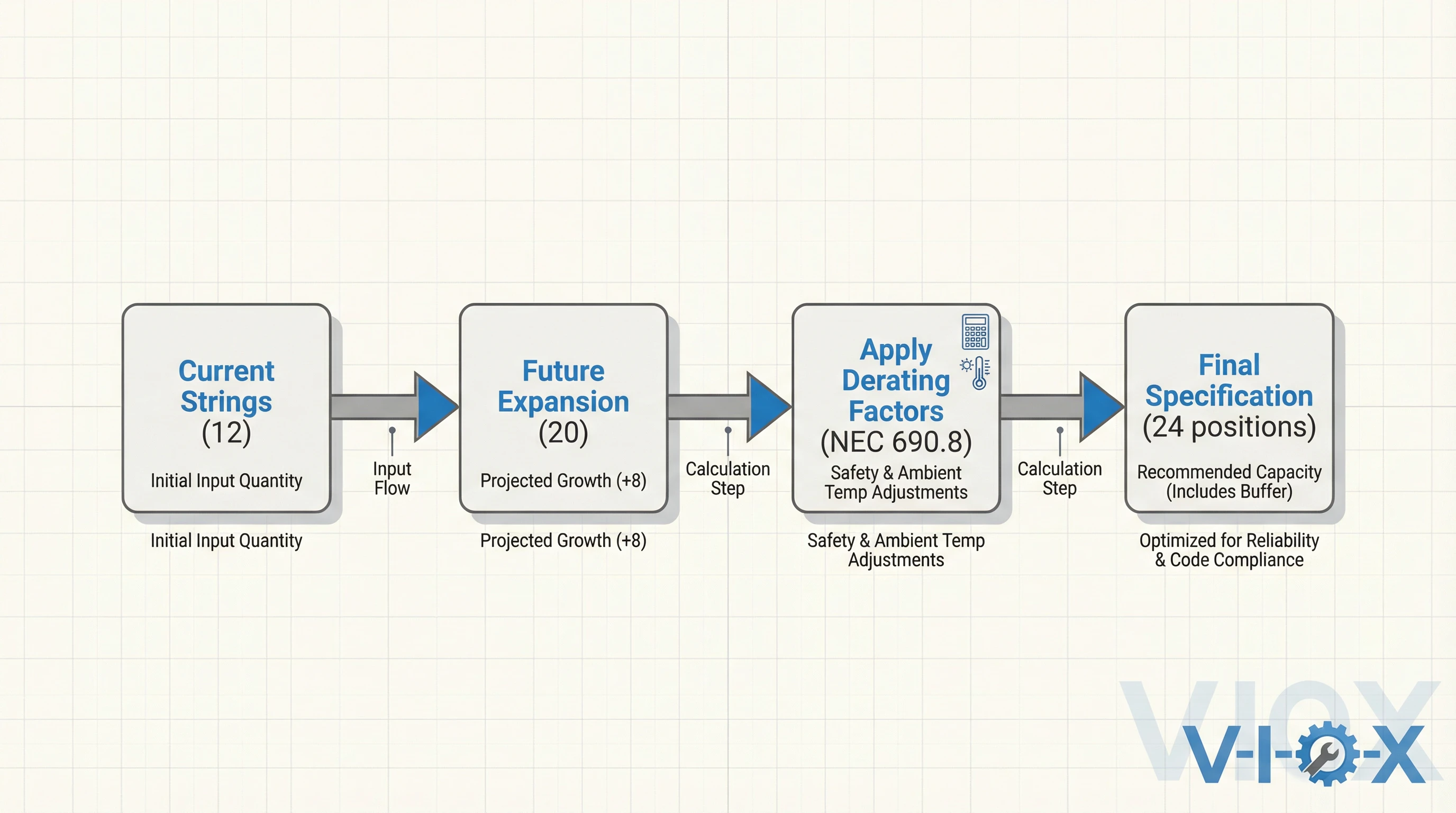
Standards-Based Approach: When combining NEC requirements with practical margins, your specification evolves from “supports 20 strings” to “supports 20 strings today with conductors and busbars rated for 24-string equivalent current, including all derating.” This disciplined approach prevents the common mistake of selecting a combiner with 20 physical positions but insufficient thermal or ampacity headroom.
Step 4: Select Position Count and Current Rating for Your Solar Combiner Box
With your calculations complete, translate technical requirements into specific product selections. This is where planning meets procurement.
Combiner Input Position Matrix: Match your target string count to available product families. If you need 20 positions for future expansion, look for combiner models offering 20–24 inputs. Many manufacturers including VIOX Electric provide modular product lines where a single enclosure platform accommodates multiple configurations—16, 18, 20, or 24 positions—allowing you to buy the physical capacity you need without custom engineering. This modularity means your electricians can add fuseholders or breakers to unpopulated positions during phase two without removing the entire combiner.
Branch Current Ratings: Verify each input terminal or fuse position supports your maximum anticipated string current. For 15A Isc modules, you need branch ratings around 18.75A (15A × 1.25). Modern high-performance combiners support branch currents up to 21A, accommodating next-generation bifacial panels and providing headroom for module technology evolution. Check that your selected OCPDs—whether PV-rated fuses or DC circuit breakers—match both the branch rating and the module’s maximum series fuse specification.
Output Busbar Ampacity: Confirm the combiner’s total output capacity meets your fully expanded, derated current requirement. For our 20-string example with 469A continuous (derated), you need busbars and output terminals rated for 500A or higher. VIOX combiner boxes specify both continuous and short-circuit busbar ratings, ensuring safe operation under all conditions including ground faults and array mismatch.
VIOX Product Example: The VIOX VSC-24-1000 solar combiner box provides 24 input positions, 1000 Vdc rating, 21A branch capacity per position, and a 600A output busbar—ideal for commercial installations planning 12–20 string growth with high-current modules. Its IP67-rated enclosure with thermal management features ensures reliable operation in harsh outdoor environments, and the modular fuse design allows incremental population as your array expands.
Practical Sizing Example: From 12 Strings to 20
Let’s work through a complete real-world scenario to cement the methodology.
Project Parameters:
- Current installation: 12 strings
- Planned expansion: 20 strings within three years
- Module specifications: Voc = 50V, Isc = 11A (current), anticipate future modules at Isc = 14A
- String configuration: 12 modules in series
- Location: Hot climate, 50°C ambient expected
- Site voltage correction factor (cold): Cv = 1.12
Step 1 – Calculate Current Requirements:
- Vmax = 50V × 12 modules × 1.12 = 672 Vdc → Select 1000 Vdc-rated combiner
- Current string Imax = 11A × 1.25 = 13.75A
- Current combined Imax = 12 strings × 13.75A = 165A
- Conductor ampacity (before derating) = 165A × 1.25 = 206A
Step 2 – Forecast Expansion:
- Target strings: 20
- Future module Isc: 14A (conservative estimate for bifacial/high-current tech)
Step 3 – Apply Derating and Margins:
- Future maximum combined current = 20 × 14A × 1.25 = 350A
- Conductor ampacity requirement = 350A × 1.25 = 437.5A
- Temperature correction (50°C, NEC Table 310.15) ≈ 0.82 for copper
- Derated conductor requirement = 437.5A ÷ 0.82 ≈ 533A
- Add 20% expansion margin = 533A × 1.20 ≈ 640A
Step 4 – Specify Equipment:
- Input positions: 24 (accommodates 20 target plus margin)
- Branch rating: 21A per position (supports 14A × 1.25 = 17.5A with headroom)
- Output busbar: 650A continuous rating minimum
- Voltage: 1000 Vdc
- OCPDs: PV-rated fuses, 15A for current strings, 20A for future (within module max series fuse limits)
Result: Specify VIOX VSC-24-1000 or equivalent: 24 positions, 1000 Vdc, 21A branch, 650A+ busbar. Populate 12 positions initially with 15A fuses and matching string wiring. Reserve 8–12 positions for expansion. Output conductors sized for 650A after all derating.
This approach costs roughly 15–20% more upfront than a minimally-sized 12-position combiner, but eliminates the need for $8,000–12,000 replacement costs, permits, and downtime during phase two—delivering a 4:1 ROI on expansion planning.
Common Sizing Mistakes to Avoid
Even experienced designers fall into predictable traps when sizing solar combiner boxes for expansion. Recognizing these mistakes saves time and budget.
Under-Provisioning Input Positions: Specifying exactly the number of positions you need today—”We have 16 strings, so we’ll buy a 16-position combiner”—is the most frequent error. When expansion arrives, you’re forced to replace the entire unit or install a second combiner downstream, adding complexity and cost. Always round up to the next available position count with margin.
Ignoring Thermal Derating: Treating a combiner’s nameplate ampacity as absolute capacity without applying NEC temperature corrections leads to oversized conductors melting terminals or nuisance breaker trips. Outdoor enclosures in direct sun can reach 60–70°C internally. VIOX Electric designs combiners with thermal headroom built in, but you must still apply code-required ampacity derating to your conductor sizing.
Mixing Incompatible OCPD Ratings: Installing 15A fuses initially, then trying to add 25A fuses later for higher-current modules, creates dangerous backfeed conditions if original string conductors aren’t rated for the increased protection. Standardize on a single OCPD rating matched to your highest anticipated string current, or document clearly which positions support which ratings.
Inflexible Combiner Placement: Mounting your combiner at the far edge of today’s array forces you to run long, costly conductor runs when you expand in a different direction. Plan combiner placement centrally relative to your ultimate array footprint, not just phase one. Consider pull boxes and conduit runs to future expansion zones during initial installation.
Skipping Documentation: Failing to record your NEC calculations, derating assumptions, and expansion rationale means the next engineer must reverse-engineer your intent—often resulting in overly conservative replacements or unsafe assumptions. Document voltage, current, temperature corrections, and position allocation in your as-built drawings and O&M manuals.
Conclusion
Sizing a solar combiner box for future string expansion isn’t guesswork—it’s systematic engineering. By calculating current requirements per NEC 690, forecasting realistic growth, applying proper derating factors, and selecting equipment with adequate position count and ampacity headroom, you create PV infrastructure that scales efficiently without costly mid-project replacements.
VIOX Electric understands that expandable systems demand more than just extra terminals. Our modular solar combiner box product lines integrate thermal management, high branch current capacity (up to 21A), and IP67 outdoor protection to support both your current installation and future phases. With voltage ratings from 1000 Vdc to 1500 Vdc and flexible input configurations (16–24 positions), VIOX combiners give you the technical foundation for growth.
Ready to specify a future-ready combiner for your next project? Contact VIOX Electric‘s engineering team for sizing consultation, technical datasheets, and custom solutions tailored to your expansion timeline. Let’s build solar infrastructure that grows with your ambitions.
