
A Reddit user asked a seemingly innocent question: “Should I install an RCD (residual current device) on the DC input side of my solar combiner box for extra safety?” Within minutes, licensed electricians and solar engineers flooded the thread with urgent warnings: Don’t do it. This is dangerous.
The answer reveals a critical misconception that puts DIY solar installations—and even some professional ones—at serious risk. If you’re used to AC electrical thinking, where “more protection equals better,” the world of photovoltaic DC circuits requires a completely different approach. Installing a standard RCD on the DC side of a solar system isn’t just ineffective—it can create a false sense of security while leaving your installation vulnerable to fire and electrocution hazards.
This guide explains why RCDs fail catastrophically in DC applications, what protection devices you actually need for PV combiner boxes, and where leakage protection really happens in modern solar systems.
Why RCDs Cannot Work on DC Circuits
The Fundamental Incompatibility
Residual Current Devices work by detecting imbalances in AC current flow. Inside every RCD sits a differential transformer (toroid) that monitors the live and neutral conductors. In a healthy AC circuit, current flowing out equals current returning, creating opposing magnetic fields that cancel each other. When leakage occurs—say, through a person touching a live wire—the imbalance creates a net magnetic field that induces current in a sensing coil, tripping the device.
This entire mechanism depends on alternating current creating constantly changing magnetic fields. Direct current produces a steady, unchanging magnetic flux that fundamentally breaks this detection method.
The Saturation Problem: RCDs Go Blind
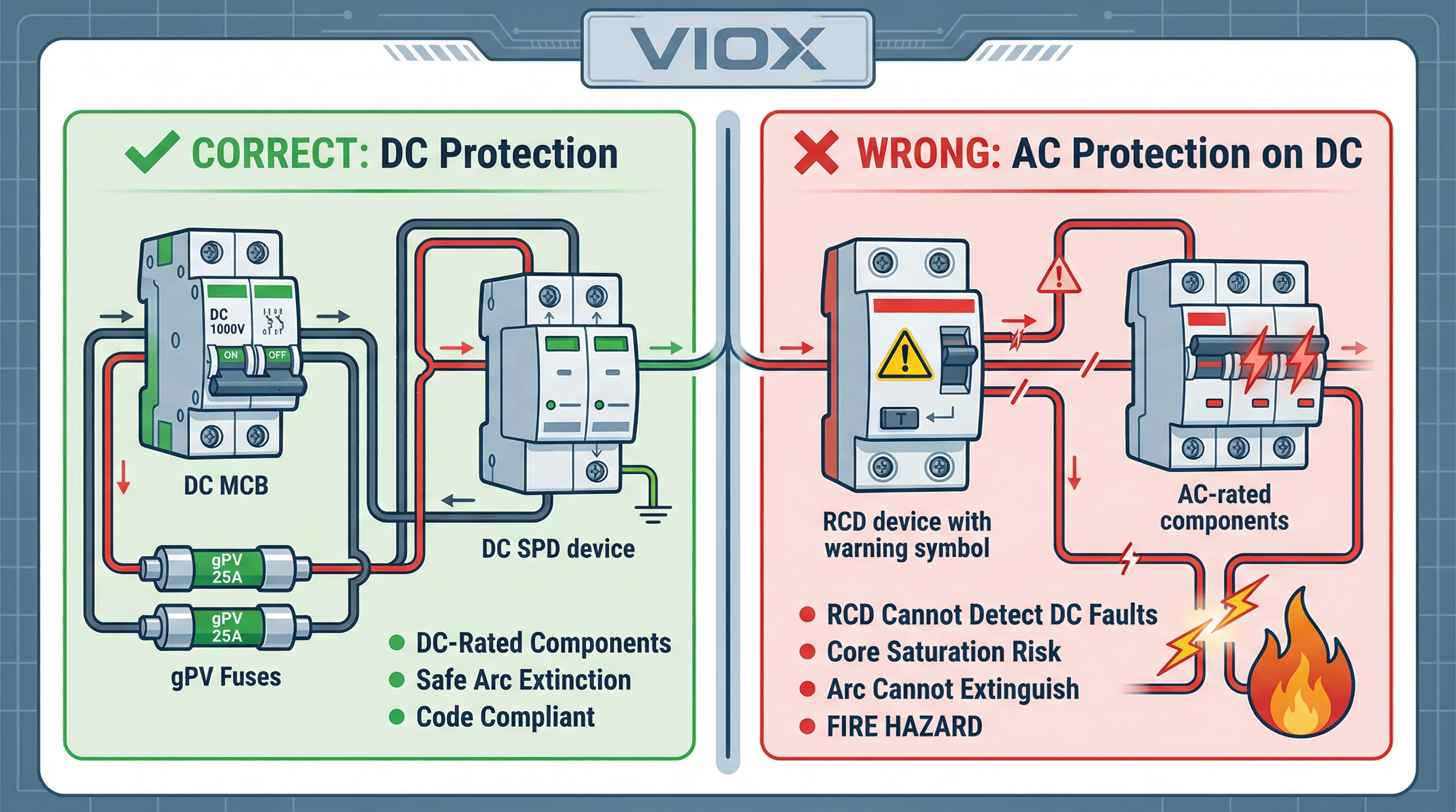
When DC leakage current flows through an RCD’s transformer, it creates a constant magnetic flux that saturates the magnetic core. A saturated core can no longer respond to changes in magnetic flux. Here’s the dangerous part: once saturated by a DC fault, the RCD becomes “blind” even to subsequent AC faults. If a dangerous AC leakage occurs after DC saturation, the RCD will not detect it and will fail to trip.
In photovoltaic systems, where insulation degradation around DC cables is common due to weather exposure, UV damage, and thermal cycling, DC leakage faults are a real and persistent threat. A Type AC RCD—the most common residential type—cannot detect these smooth DC residual currents and may fail silently.
Table 1: RCD Types and DC Compatibility
| RCD Type | Detects AC Faults | Detects Pulsating DC | Detects Smooth DC | DC Saturation Risk | Suitable for PV DC Side? |
|---|---|---|---|---|---|
| Type AC | ✓ | ✗ | ✗ | High (saturates at any DC component) | NO – Dangerous |
| Type A | ✓ | ✓ | ✗ (blinds at >6mA) | Medium (saturates above 6mA DC) | NO – Dangerous |
| Type F | ✓ | ✓ | ✗ (blinds at >10mA) | Medium (saturates above 10mA DC) | NO – Dangerous |
| Type B | ✓ | ✓ | ✓ | Low (electronic design) | NO – Wrong application |
Critical note: Even Type B RCDs, which can detect smooth DC, are designed for AC circuits with potential DC contamination. They do not replace proper DC overcurrent and arc fault protection.
Why DC Arcs Are More Dangerous
Beyond detection, there’s a second critical problem: arc extinction. AC current crosses zero 100 times per second (in 50Hz systems), providing natural moments when arcs can extinguish. At these zero-crossing points, arc energy drops to minimum, allowing the gap to deinsulate and preventing restrike.
DC has no zero-crossings. Once a DC arc establishes, it sustains indefinitely as long as voltage and current are sufficient. Standard AC-rated switches and RCDs lack the magnetic blowout coils, arc chutes, and elongation mechanisms needed to forcibly extinguish DC arcs. Using an AC RCD on a DC circuit means that even if it somehow detected a fault, opening its contacts would likely result in sustained arcing, contact welding, or device destruction.
The DC Protection Trinity: What Actually Belongs in Your Combiner Box
Instead of RCDs, PV combiner boxes require three specialized DC-rated protection devices. Each serves a distinct function that RCDs cannot provide.
1. DC-Rated MCB (Miniature Circuit Breaker)
Function: Overcurrent and short-circuit protection for the combined array output.
Why DC-specific matters: DC MCBs incorporate magnetic blowout coils that generate a magnetic field to stretch and force the arc into arc chutes. These chutes split the main arc into multiple smaller series arcs, dramatically increasing arc voltage and resistance until the circuit can no longer sustain it. This “high-resistance interruption method” is fundamentally different from the “zero-current interruption” used in AC breakers.
DC MCBs must be rated for the system’s maximum open-circuit voltage (Voc) at the lowest expected temperature—typically 600V or 1000V for residential systems. The current rating should handle the sum of all string maximum currents (Isc × 1.25 for each string) with an additional 125% safety factor for continuous duty.
Typical specification for 6-string system (14A Isc per string):
- Total maximum current: 6 × 14A × 1.25 = 105A
- MCB rating with 125% factor: 105A × 1.25 = 131.25A
- Selected rating: 150A DC MCB, 1000V rating
2. DC Fuses (gPV-Rated)
Function: String-level overcurrent protection and reverse current protection.
Critical application: When one string develops a fault, healthy strings can feed reverse current into it. Without fuses, this exceeds the module’s maximum series fuse rating (20A-30A), causing cable overheating and fire.
gPV fuses (IEC 60269-6) feature high DC voltage ratings (600V, 1000V, 1500V), DC interrupting capacity for parallel string faults, and thermal characteristics for continuous outdoor operation.
Sizing per NEC 690.9: Fuse rating ≥ Isc × 1.56
For 14.45A Isc: 14.45A × 1.56 = 22.54A → select 25A gPV fuse
3. DC SPD (Surge Protection Device)
Function: Lightning and transient overvoltage protection.
Solar arrays act as lightning attractors. DC SPDs use MOVs or GDTs to clamp overvoltages and divert surge current to ground.
Key specifications:
- Voltage rating (Uc) must exceed system maximum Voc
- Maximum discharge current (Imax): 20kA-40kA for Type 2 SPDs
- Voltage protection level (Up) below inverter maximum input
SPDs are sacrificial devices requiring inspection after surge events.
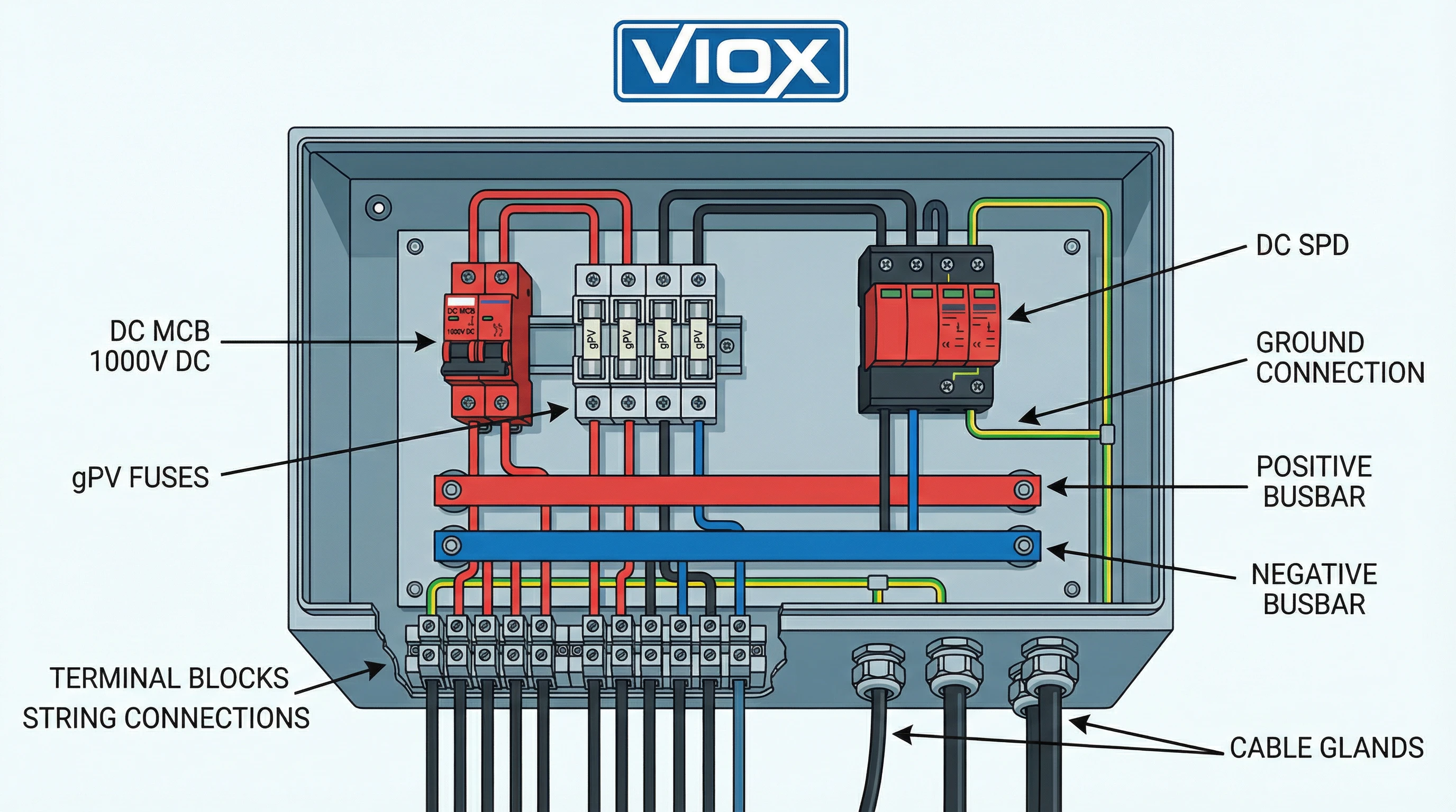
Table 2: Component Selection Matrix – Where Each Device Goes
| Location | Overcurrent Protection | Reverse Current Protection | Surge Protection | Leakage/Insulation Monitoring |
|---|---|---|---|---|
| String Level | Optional (if >3 parallel strings) | gPV Fuse (mandatory) | Optional (string SPD) | — |
| Combiner Box Output | DC MCB (mandatory) | — | DC SPD (mandatory) | — |
| Inverter DC Input | Integrated in inverter | Integrated in inverter | May have Type 2 SPD | RCMU/ISO monitoring |
| Inverter AC Output | AC MCB/MCCB | — | AC SPD | Type A or Type B RCD |
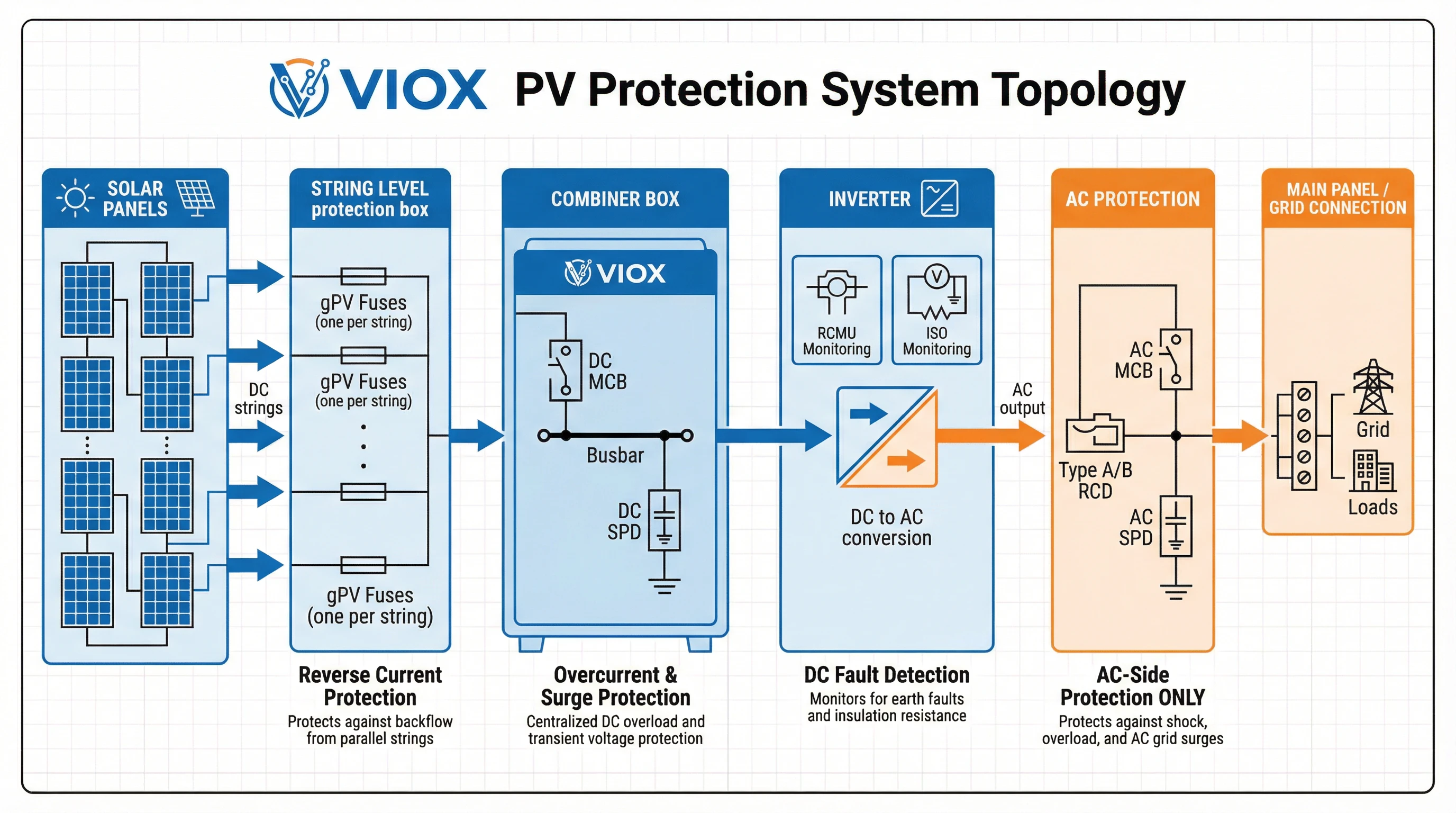
Where Leakage Protection Actually Happens: The Inverter’s Job
If you’re not installing an RCD on the DC side, where does leakage protection come from? The answer: modern grid-tie inverters.
RCMU: Residual Current Monitoring Unit
Modern inverters integrate RCMU (Residual Current Monitoring Unit) that monitors AC and DC residual currents. Unlike RCDs that mechanically trip, RCMUs signal the inverter to shut down when faults are detected.
RCMU operating thresholds:
- Sudden change ≥30mA triggers shutdown within 0.3 seconds
- Continuous leakage ≥300mA triggers shutdown
- Self-test failure prevents inverter startup
ISO Monitoring: Inverters test insulation resistance before grid connection each morning. If below 1 Megohm, the inverter refuses to operate. Advanced models offer real-time monitoring.
These integrated protections handle the exact function installers mistakenly try to achieve with DC-side RCDs—but with technology specifically designed for DC fault detection.
AC Side RCD: The One Place RCDs Belong
RCDs do have a role in solar systems: on the AC output side, after the inverter converts DC to AC.
Location: Between the inverter’s AC output and the main electrical panel.
Type selection depends on inverter design:
Table 3: AC-Side RCD Requirements by Inverter Type
| Inverter Type | DC-AC Isolation | Smooth DC Leakage Risk | Required RCD Type | Reasoning |
|---|---|---|---|---|
| Isolated (with transformer) | Galvanic separation | None | Type A | Transformer blocks DC faults from reaching AC side |
| Non-isolated (transformerless) | No separation | High | Type B | DC faults can leak to AC side; Type A would saturate |
Why Type B for transformerless inverters: Without galvanic isolation, DC-side insulation faults can allow smooth DC current onto the AC circuit. Type A RCDs tolerate only 6mA DC before saturating. Type B RCDs use electronic sensing that remains functional with smooth DC present.
Always consult manufacturer documentation. Some manufacturers (SolarEdge) allow Type A RCDs; others (SMA) require Type B for transformerless models. When in doubt, Type B provides maximum protection.
Common Configuration Errors and Corrections
Table 4: Dangerous Mistakes and Proper Solutions
| Error | Why It’s Dangerous | Correct Solution |
|---|---|---|
| Installing Type AC RCD on DC input | Cannot detect DC faults; saturates and becomes blind to all faults; contacts cannot break DC arc safely | Use DC MCB + gPV fuses; rely on inverter RCMU for leakage detection |
| Using AC-rated fuses in combiner box | Lack DC interrupting capacity; can explode when attempting to clear DC fault current | Always specify gPV-rated fuses (IEC 60269-6) with proper DC voltage rating |
| Oversizing fuses “for future expansion” | 30A fuse on 10A string won’t protect against reverse overcurrent; defeats purpose of fuse | Size fuses per NEC 690.9 (Isc × 1.56); upsize combiner box/busbar instead |
| Omitting SPD to save cost | Lightning-induced transients destroy inverters; insurance often won’t cover improper installation | Install DC SPD at combiner output; consider AC SPD at panel as well |
| Using Type A RCD with transformerless inverter | Type A saturates with >6mA smooth DC; fails to protect against DC-contaminated AC faults | Verify inverter type; use Type B RCD for non-isolated designs per IEC 60364-7-712 |
| Installing DC MCB without verifying DC rating | AC MCBs fail catastrophically when interrupting DC; can weld contacts or explode | Verify clear “DC” marking and voltage rating ≥ system Voc at minimum temperature |
Equipment Specification Checklist
Before purchasing components for your PV combiner box, verify these specifications:
DC MCB:
- DC voltage rating ≥ system Voc at lowest ambient temperature
- Current rating ≥ (total string Isc × 1.25) × 1.25
- Clear “DC” marking on device
- Interrupting capacity (Icu) ≥ maximum prospective fault current
gPV Fuses:
- IEC 60269-6 gPV classification marking
- Current rating = Isc × 1.56 rounded to next standard size
- Voltage rating ≥ 1.2 × system Voc
- Rating does not exceed module maximum series fuse rating
DC SPD:
- Rated continuous operating voltage (Uc) ≥ system Voc
- Type 2 classification minimum (Type 1 if no upstream SPD)
- Maximum discharge current (Imax) ≥ 20kA
- Voltage protection level (Up) below inverter maximum input voltage
Inverter:
- Integrated RCMU or equivalent DC fault detection
- Insulation resistance monitoring (ISO)
- Documentation specifies required AC-side RCD type
Frequently Asked Questions
Q: My AC electrician says we always use RCDs for safety. Why not on the DC side?
A: RCDs are designed exclusively for alternating current. Their detection mechanism relies on changing magnetic fields that only AC produces. DC creates a steady magnetic flux that saturates the RCD’s core, making it unable to detect faults—AC or DC. Additionally, RCD contacts cannot safely interrupt DC arcs, which lack the natural zero-crossings that AC provides. Using an RCD on DC is not “extra safety”—it’s a non-functional component creating false confidence.
Q: Can I use a Type B RCD on the DC side since it detects smooth DC?
A: Type B RCDs detect smooth DC residual currents, but they’re designed for AC circuits with potential DC contamination (like inverter outputs). They don’t replace the overcurrent, reverse current, and arc fault protection that DC MCBs and gPV fuses provide. More importantly, even Type B RCDs may lack the DC interrupting capacity and arc extinction mechanisms needed for high-voltage PV arrays. The correct approach is DC-specific protection devices on the DC side, with Type B RCD on the AC output if required by inverter design.
Q: What if my combiner box came with RCD mounting space?
A: Some imported combiner boxes include universal DIN rail mounting space without being designed for specific markets or codes. Just because there’s physical space doesn’t mean you should install an RCD. Follow NEC Article 690 (North America) or IEC 62548 (international) requirements: DC MCB, gPV fuses, and DC SPD. Leave the extra space empty or use it for additional string positions if your busbar supports it.
Q: How do I know if my inverter has RCMU and ISO monitoring?
A: Check the inverter datasheet or installation manual. Modern grid-tie inverters from reputable manufacturers (SMA, Fronius, SolarEdge, Solis, Huawei, etc.) all include these features as standard, often listing them under “Safety” or “Protection Features.” Look for terms like “Residual Current Monitoring Unit (RCMU),” “Insulation Resistance Monitoring,” “Ground Fault Detection,” or “ISO monitoring.” If you can’t find this information, contact the manufacturer—any inverter sold after 2015 for grid connection should have integrated DC fault detection.
Q: My local inspector requires an RCD. What do I tell them?
A: Ask specifically where the RCD should be installed. If they mean the AC output side between inverter and main panel, that’s correct—install Type A or Type B per inverter manufacturer specifications. If they insist on DC-side RCD, politely reference:
- NEC 690.41 (requires system ground fault protection, which inverter RCMU provides)
- NEC 690.9 (requires DC overcurrent protection via DC-rated devices)
- IEC 62548 Section 8.2 (DC circuit protection requirements—does not include RCDs)
- IEC 60364-7-712 Section 712.413.1.1.1.2 (specifies Type B RCD for AC side of non-isolated systems)
Provide the inverter’s technical documentation showing integrated RCMU/ISO fault detection. Most inspection issues arise from confusion between AC-side and DC-side requirements.
Q: Can I DIY a solar combiner box, or should I buy pre-assembled?
A: If uncertain about component selection or sizing calculations, purchase a pre-engineered combiner box from VIOX Electric. These come with correctly rated DC MCBs, gPV fuse holders, SPDs, and busbars. DIY is feasible only if you thoroughly understand NEC 690/IEC 62548 requirements and can source genuinely DC-rated components.
Protect Your Investment With Proper DC Protection
The takeaway is clear: abandon AC electrical thinking when you enter the DC world of photovoltaic systems. RCDs—whether Type AC, A, F, or even B—have no place on the DC input side of solar combiner boxes. They cannot detect the faults that matter, will blind themselves to subsequent faults, and cannot safely interrupt DC arcs.
The correct protection strategy follows the DC trinity:
- DC-rated MCB for overcurrent and short-circuit protection
- gPV-rated fuses for string-level reverse current protection
- DC SPD for lightning and surge protection
Leakage and insulation fault monitoring happens inside the inverter via RCMU and ISO systems specifically designed for DC fault detection. On the AC output side—and only there—install the appropriate Type A or Type B RCD per inverter manufacturer specifications.
VIOX Electric manufactures complete lines of PV combiner boxes, DC-rated MCBs, gPV fuses, and DC SPDs engineered to meet both NEC and IEC standards. Our pre-configured combiner boxes eliminate guesswork in component selection and sizing. For technical support, sizing calculations, or product datasheets, visit VIOX.com or contact our solar protection specialists. Don’t let AC assumptions compromise your DC safety.
