
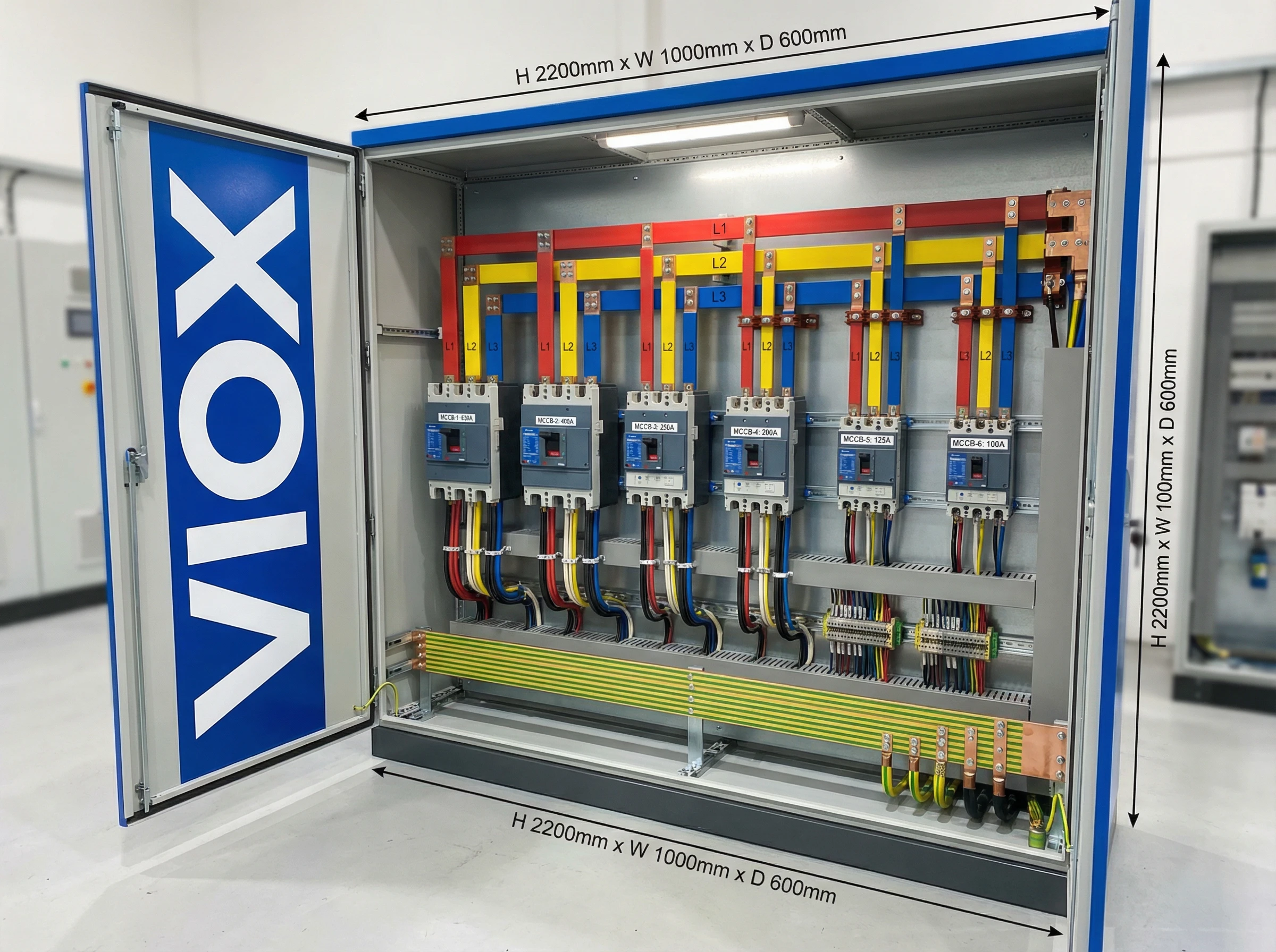
In modern industrial electrical distribution systems, busbar systems serve as the backbone for power distribution, channeling electricity from main sources to various circuit protection devices and loads. The connection between molded case circuit breakers (MCCBs) and busbars represents a critical junction point where improper installation can lead to overheating, system failures, and safety hazards. Industry data shows that loose or improperly torqued busbar connections account for a significant percentage of electrical panel failures.
This comprehensive guide explores the technical requirements, installation best practices, and protection coordination strategies for MCCB-busbar connections. Whether you’re designing a new switchgear assembly or maintaining existing distribution panels, understanding proper connection methods ensures system reliability, compliance with IEC standards, and long-term operational safety. From torque specifications to selective coordination, we’ll cover everything electrical engineers and installation professionals need to know about this essential interface.
Understanding Busbar Systems and MCCB Integration
What Are Busbar Systems?
A busbar is a metallic conductor—typically made of copper or aluminum—that distributes electrical power within switchgear, panel boards, and distribution assemblies. Unlike cables, busbars offer low impedance, high current-carrying capacity, and compact installation in enclosed systems. They form the main distribution arteries in industrial facilities, commercial buildings, and power generation plants.
Busbars come in various configurations: flat bars, hollow sections, or specialized profiles designed for specific current ratings. The material choice significantly impacts performance—copper busbars provide excellent conductivity and durability, while aluminum offers a lighter, more cost-effective alternative for certain applications.
Why MCCBs for Busbar Distribution?
Molded Case Circuit Breakers serve as the primary overcurrent protection devices in busbar distribution systems. Compared to miniature circuit breakers (MCBs), MCCBs handle higher current ratings (typically 16A to 1600A) and provide adjustable trip settings for both thermal overload and magnetic short-circuit protection.
The integration of MCCBs with busbar systems offers several advantages:
- High breaking capacity: Modern MCCBs provide short-circuit breaking capacity (Icu) ranging from 25kA to 150kA, essential for protecting high-power busbar systems
- Compact installation: Direct busbar connection eliminates bulky cable connections and reduces panel space requirements
- Flexible configuration: Multiple MCCBs can connect to a single busbar system, creating efficient radial or selective distribution networks
- Reliable protection: The thermal-magnetic or electronic trip units protect downstream circuits while coordinating with upstream devices for system selectivity
According to IEC 61439 standards for low-voltage switchgear assemblies, proper MCCB-busbar integration must demonstrate verified temperature rise limits and short-circuit withstand capability through testing or design verification.
Connection Methods and Best Practices
Proper connection between MCCBs and busbars forms the foundation of reliable electrical distribution. Poor connections create high resistance joints that generate excessive heat, leading to equipment failure, fire hazards, and unplanned downtime.
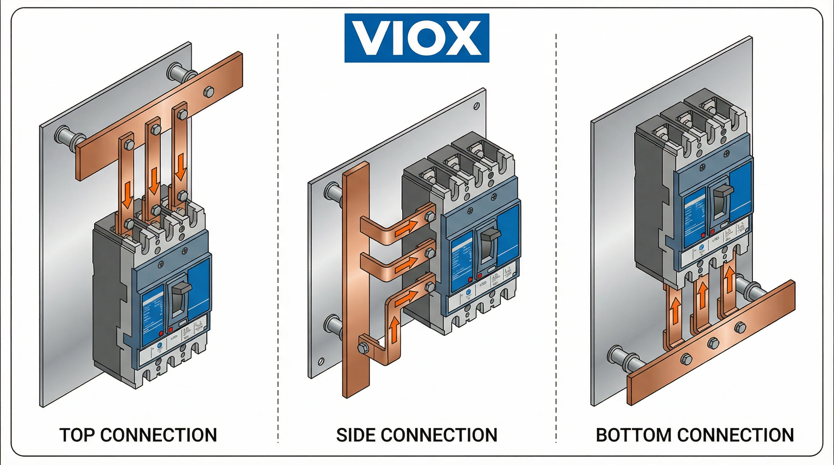
Types of Busbar Connection Methods
1. Direct Bolt Connection
The most common method involves bolting the MCCB terminals directly to the busbar using high-grade fasteners. The MCCB’s terminal pads mate flush against the prepared busbar surface, creating a metal-to-metal contact interface. This method requires:
- Flat, clean contact surfaces on both busbar and MCCB terminals
- Proper alignment to prevent mechanical stress
- Manufacturer-specified torque values for optimal clamping force
2. Lug-Based Connection
Some installations use compression lugs or mechanical connectors between the busbar and MCCB terminals. This approach provides flexibility when the MCCB mounting position doesn’t align perfectly with the busbar, but adds an additional connection point that must be properly maintained.
3. Plug-On/Comb Busbar Systems
Certain MCCB designs feature plug-on capabilities for rapid installation onto specially designed comb busbars or busbar adapters. These systems ensure consistent connection quality but require compatible MCCB models and busbar profiles.
Critical Torque Specifications
Applying correct torque represents the single most important factor in busbar connection reliability. Under-torqued connections create high-resistance joints that overheat; over-torqued fasteners damage threads and deform contact surfaces.
Always follow the MCCB manufacturer’s specified torque values. As a reference guide, typical ranges include:
| MCCB Frame Size | Terminal Bolt Size | Typical Torque Range |
|---|---|---|
| Up to 100A | M6 | 5-10 Nm (44-88 lb-in) |
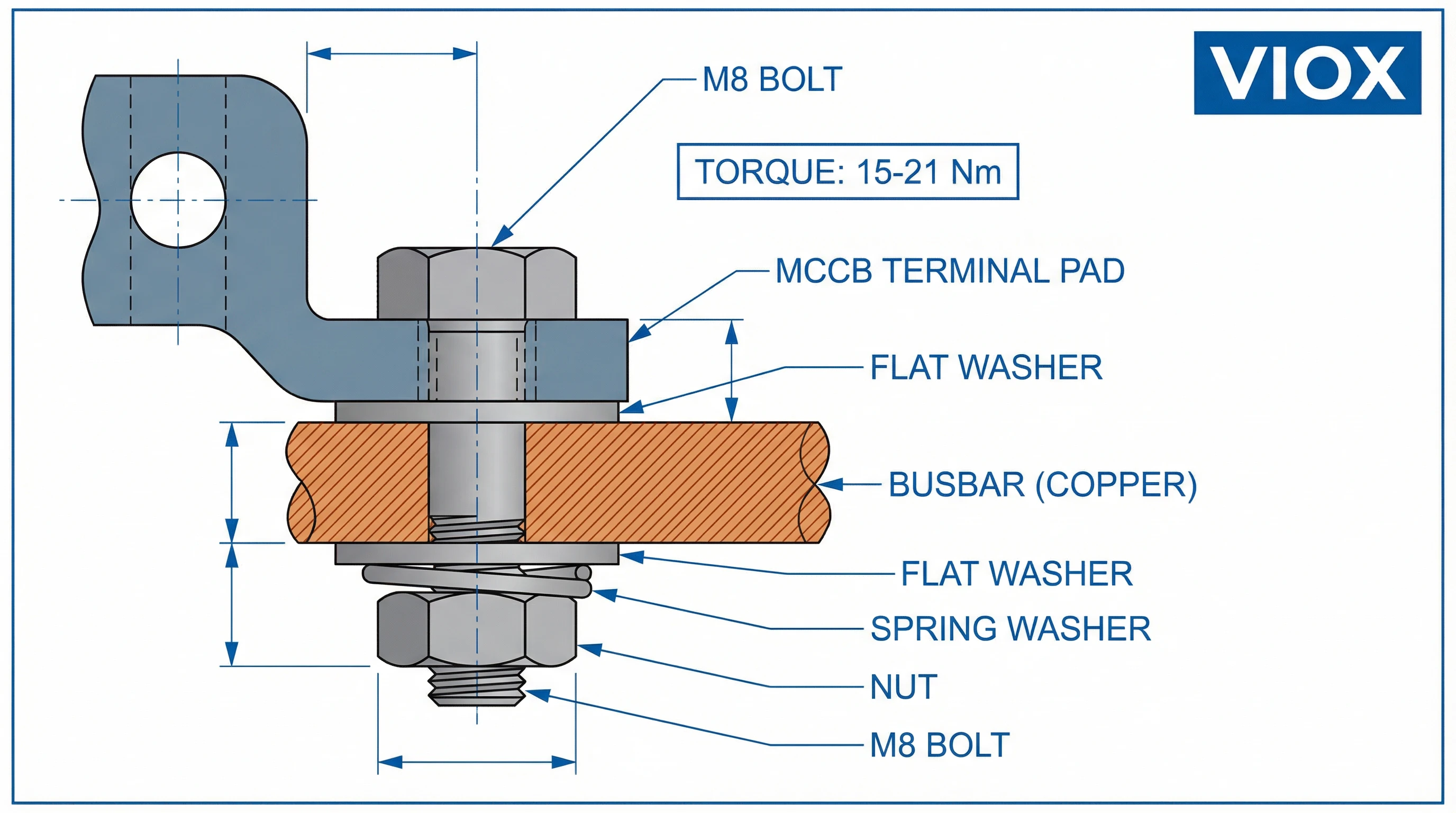
| 125-250A | M8 | 15-21 Nm (133-186 lb-in) |
| 400-630A | M10 | 30-50 Nm (265-442 lb-in) |
| 800A and above | M12 or larger | 50-70 Nm (442-619 lb-in) |
Note: These values are illustrative. Always consult VIOX MCCB technical documentation for exact specifications.
Essential torque application practices:
- Use a calibrated torque wrench—never estimate by feel
- Apply torque in a progressive sequence if multiple bolts secure one connection
- Re-check torque values after initial energization (thermal cycling can affect joint tightness)
- Document torque verification as part of commissioning records
Surface Preparation and Contact Treatment
The quality of the metal-to-metal interface directly affects connection resistance and long-term reliability.
For Copper Busbars:
- Remove any oxidation or surface contamination using a non-abrasive cleaner
- Light abrasion with fine emery cloth can improve surface finish
- Clean with isopropyl alcohol and allow to dry completely
- Make connection immediately after preparation to minimize re-oxidation
For Aluminum Busbars:
- Remove the oxide layer using a stainless steel brush or abrasive pad
- Apply a thin layer of aluminum-rated anti-oxidant compound
- Complete the connection promptly—aluminum oxidizes rapidly when exposed to air
- The anti-oxidant compound prevents reformation of high-resistance oxide layers
Mixed Metal Connections (Copper-Aluminum):
Connecting copper MCCBs to aluminum busbars or vice versa requires special consideration due to galvanic corrosion potential. Use:
- Bi-metallic transition plates or washers
- Anti-oxidant compound rated for both metals
- Stainless steel hardware to minimize galvanic cell formation
Hardware and Washer Selection
Proper fasteners ensure reliable long-term connections:
- Bolt grade: Use Class 8.8 or higher steel bolts as specified by manufacturer
- Flat washers: Distribute clamping pressure evenly across contact surfaces
- Spring washers or Belleville washers: Maintain clamping force despite thermal expansion/contraction cycles
- Lock washers: Prevent fastener loosening from vibration (common in motor control applications)
Never substitute fasteners with lower-grade hardware. The few cents saved can lead to catastrophic connection failures.
Connection Configuration and Alignment
Physical alignment between MCCB and busbar affects both mechanical integrity and electrical performance:
- Verify the MCCB mounting position allows natural, stress-free contact with the busbar
- Avoid forcing misaligned connections—misalignment indicates design or installation errors
- For multi-pole MCCBs, ensure all phases make simultaneous, equal contact
- Maintain proper phase spacing and creepage distances per IEC 61439 requirements
- Consider thermal expansion—rigid connections in long busbar runs may require expansion joints
VIOX MCCBs feature precision-engineered terminal designs that facilitate proper busbar alignment when installed according to mounting templates and dimensional specifications.
Protection Coordination and Safety Considerations
Short-Circuit Protection Requirements
Busbar systems must withstand the mechanical and thermal stresses imposed by fault currents until upstream protection devices clear the fault. The short-circuit withstand rating (Icw) of the busbar system and connected MCCBs must exceed the prospective fault current at the installation point.
Key protection parameters:
- Icu (Ultimate Short-Circuit Breaking Capacity): The maximum fault current the MCCB can interrupt, though it may not remain serviceable afterward
- Ics (Service Short-Circuit Breaking Capacity): The fault current level the MCCB can interrupt and remain in service (typically 50-100% of Icu)
- Icw (Short-Time Withstand Current): Critical for busbar systems—the current the MCCB and busbar can withstand for a specified duration (typically 0.05-3 seconds) without damage
For busbar distribution systems, the MCCB’s Icw rating must coordinate with the busbar’s short-time current rating to prevent damage during fault conditions.
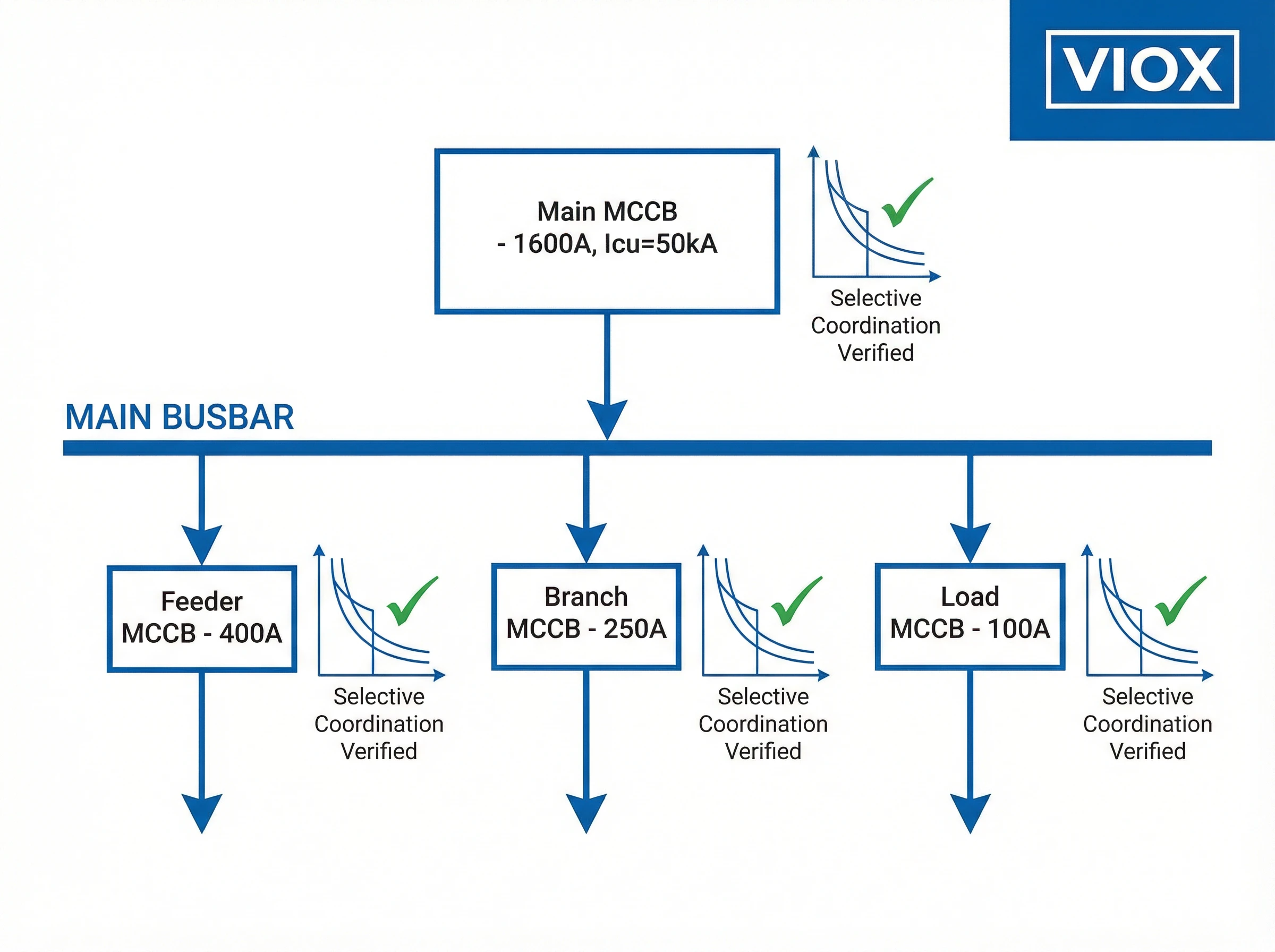
Selective Coordination and Discrimination
Selectivity (or discrimination) ensures that only the protective device closest to a fault operates, leaving upstream circuits energized. Proper MCCB-busbar system design achieves selectivity through careful coordination of time-current characteristics.
Three types of selectivity apply to busbar systems:
1. Total Selectivity: The upstream MCCB never trips for any fault current that causes the downstream device to operate. This ideal scenario requires significant time-current separation between devices.
2. Partial Selectivity: Discrimination exists up to a specified fault current level. Beyond this threshold, both devices may trip. The selectivity limit must be documented and compared against actual fault current calculations.
3. Energy Selectivity: Leverages the current-limiting characteristics of modern MCCBs. High-speed current limitation of downstream devices prevents upstream devices from seeing sufficient let-through energy to trip.
Coordination studies should verify selectivity across the full range of fault currents, from minimum (end-of-line) to maximum (busbar fault) values. VIOX provides selectivity tables and coordination software to simplify this analysis for our MCCB product ranges.
Thermal Management and Temperature Rise
Busbar connections generate heat through I²R losses. Poorly made connections exhibit higher resistance, producing excessive temperature rise that can:
- Degrade insulation materials and reduce equipment lifespan
- Cause nuisance tripping of thermal protection elements
- Create hot spots visible during thermographic inspection
- Ultimately lead to connection failure and arc flash hazards
IEC 61439 specifies maximum temperature rise limits for different components:
- Busbar terminals: Typically 70-80K above ambient
- Connection points: Must not exceed material ratings (commonly 90-105K)
- Enclosed spaces: Require adequate ventilation to dissipate heat
Proper connection torque, clean contact surfaces, and appropriate conductor sizing all contribute to minimizing temperature rise. VIOX MCCBs undergo rigorous temperature rise testing per IEC 60947-2 to verify thermal performance at rated currents.
Grounding and Neutral Considerations
Complete busbar systems include provisions for grounding and neutral conductors:
- Ground/PE busbar: Must provide low-impedance path to earth for fault current and equipment grounding
- Neutral busbar: In 3-phase + neutral systems, consider whether to use 3-pole or 4-pole MCCBs
- Ground fault protection: Some applications require residual current monitoring or ground fault relays coordinated with the MCCB protection
For TN-S systems (separate protective earth), use 3-pole MCCBs with switched phases only. TN-C or IT systems may require 4-pole MCCBs with switched neutral. Always verify system grounding configuration before specifying MCCB pole configuration.
Step-by-Step Installation Guidelines
Following a systematic installation procedure ensures safety, reliability, and compliance with electrical standards. This section outlines the professional approach to MCCB-busbar connection.
Pre-Installation Safety and Preparation
Before beginning any work:
- De-energize the system: Verify zero voltage using a properly rated test instrument. Never rely on indicator lights or circuit labels alone.
- Lock-out/tag-out (LOTO): Apply appropriate lockout procedures per facility safety protocols
- Wait for discharge: Allow adequate time for capacitors in connected equipment to discharge
- Verify equipment ratings: Confirm MCCB ratings match design specifications (voltage, current, breaking capacity)
- Inspect components: Check busbars, MCCBs, and hardware for shipping damage or defects
- Review drawings: Confirm installation matches approved single-line diagrams and panel layouts
Installation Procedure
Step 1: Busbar Preparation
- Verify busbar material, dimensions, and current rating
- Clean contact surfaces as described in Surface Preparation section
- For aluminum busbars, apply anti-oxidant compound immediately before connection
- Check busbar support insulators for proper mounting and creepage distances
Step 2: MCCB Mounting
- Position the MCCB on its mounting plate or DIN rail according to panel layout
- Ensure proper orientation (typically with operator handle accessible from front)
- Verify mounting hardware is secure before attempting busbar connection
- Check that adjacent devices maintain required spacing
Step 3: Terminal Connection
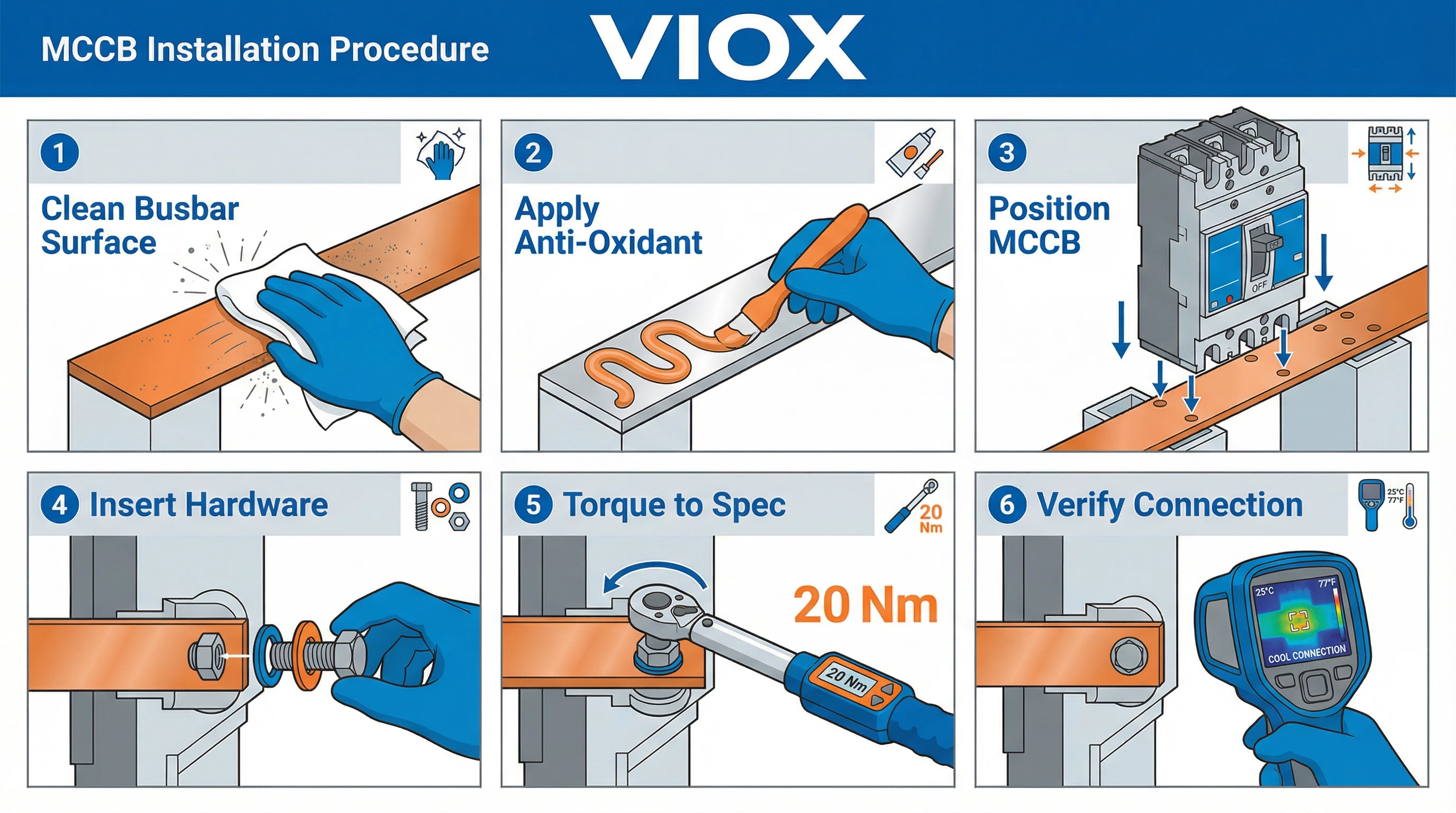
- Align MCCB terminals with prepared busbar contact points
- Insert appropriate grade bolts through MCCB terminals and busbar
- Install flat washers against both MCCB terminal and bolt head
- Add spring washers or Belleville washers as specified
- Hand-tighten fasteners to seat all components
Step 4: Torque Application
- Use a calibrated torque wrench set to manufacturer-specified value
- Apply torque in a progressive manner if multiple bolts secure one terminal
- For multi-pole MCCBs, torque all phases to identical values
- Mark completed connections with torque verification indicator (paint dot or marker)
Step 5: Visual Inspection
Verify:
- All terminal connections show uniform compression (no gaps visible)
- Hardware is properly seated with no cross-threading
- Conductors and busbars maintain proper spacing and creepage
- No foreign objects or debris remain in the panel
- MCCB position allows free operation of the handle mechanism
Step 6: Electrical Testing
- Measure insulation resistance with a megger (typically 1000V DC for LV systems)
- Results should exceed 1 MΩ to ground and between phases
- Perform continuity checks across connections
- Verify operation of MCCB mechanism (manual open/close operations)
Step 7: Energization and Verification
- Perform graduated energization if possible (single-phase, then three-phase)
- Monitor connections for abnormal heating during initial loading
- Use infrared thermography within 24-72 hours of commissioning to detect hot spots
- Verify MCCB trip characteristics through primary injection testing if required
- Document installation completion, test results, and as-built conditions
Common Installation Mistakes to Avoid
- Skipping surface preparation: Oxidized or contaminated surfaces create high-resistance connections
- Estimating torque values: “Tight enough” is not a specification—use calibrated tools
- Mixing hardware: Using non-specified bolts, washers, or connectors compromises reliability
- Forcing misalignment: If connections don’t align naturally, investigate and correct the root cause
- Over-tightening: Excessive torque damages threads and warps contact surfaces
- Inadequate spacing: Maintain clearances per IEC 61439 to prevent flashover
- Poor documentation: Failing to record torque values and test results creates maintenance challenges
VIOX provides comprehensive installation manuals, torque specifications, and dimensional drawings for all MCCB models to support proper field installation.
Troubleshooting Common Connection Issues
Even properly installed MCCB-busbar connections can develop problems over time. Regular inspection and prompt troubleshooting prevent minor issues from escalating into system failures.
Overheating at Connection Points
Symptoms: Discolored terminals, melted insulation, thermal imaging hot spots, burnt smell
Probable Causes:
- Insufficient torque leading to high contact resistance
- Oxidation or contamination on contact surfaces
- Undersized busbar for actual load current
- Loose connection due to thermal cycling or vibration
Solutions: De-energize the system and re-torque connections to specification. If oxidation is present, disassemble, clean surfaces, and reconnect. Consider upgrading to larger busbar if thermal calculations indicate undersizing.
Nuisance Tripping
Symptoms: MCCB trips without apparent overload or short circuit
Probable Causes:
- High-resistance connections causing localized heating that affects thermal trip element
- Ambient temperature exceeding MCCB rating
- Harmonic currents or motor inrush not accounted for in sizing
- Deteriorated trip unit calibration
Solutions: Verify all connections are properly torqued and show no thermal damage. Check ambient temperature and compare against MCCB derating curves. Analyze load characteristics for harmonics or high inrush currents. Consider replacing MCCB if trip unit calibration has drifted.
Visible Arcing or Sparking
Symptoms: Visible light emission, carbon tracking, pitting on contact surfaces
Probable Causes:
- Inadequate contact pressure due to loose connection
- Movement or vibration at connection interface
- Contamination allowing tracking across insulation surfaces
Solutions: Immediate shutdown required—arcing connections represent fire and shock hazards. After de-energization, inspect for damage. Replace damaged components, thoroughly clean and prepare surfaces, reconnect with proper torque, and verify all hardware is secure.
Preventive Maintenance Recommendations
- Thermal scanning: Annual infrared thermography during loaded conditions
- Torque verification: Re-check critical connections every 1-3 years
- Visual inspection: Quarterly inspection for signs of overheating, loosening, or contamination
- Connection cleaning: Inspect and clean connections during scheduled maintenance shutdowns
- Documentation: Maintain records of inspection findings and corrective actions
Frequently Asked Questions
Q: What is the most critical factor in MCCB-busbar connections?
Proper torque application using calibrated tools represents the single most important factor. Under-torqued connections create high-resistance joints that overheat and fail, while over-torquing damages threads and contact surfaces. Always follow manufacturer specifications and use a calibrated torque wrench.
Q: Can I connect copper MCCBs directly to aluminum busbars?
Yes, but special precautions are required. Use bi-metallic transition washers or plates, apply anti-oxidant compound rated for both metals, and use stainless steel fasteners to minimize galvanic corrosion. The connection requires more frequent inspection compared to same-metal joints.
Q: How often should busbar connections be inspected?
Visual inspections should occur quarterly. Annual infrared thermography during loaded conditions identifies developing hot spots before they cause failures. Torque verification should be performed every 1-3 years, or after any significant electrical event such as a short circuit or overload trip.
Q: What torque wrench accuracy is acceptable for MCCB connections?
Use torque wrenches with ±4% accuracy or better, calibrated within the last 12 months. The wrench’s operating range should include the target torque value within its middle 60% range (between 20% and 80% of the wrench’s maximum capacity) for optimal accuracy.
Q: Do I need 3-pole or 4-pole MCCBs for busbar systems?
This depends on the system grounding configuration. TN-S systems (separate protective earth) typically use 3-pole MCCBs with switched phases only. TN-C systems or installations requiring neutral switching need 4-pole MCCBs. IT systems may require 3-pole or 4-pole depending on whether neutral must be switched. Always verify system grounding before specifying.
Q: How can I verify proper connection quality after installation?
Perform insulation resistance testing (megger test) to verify electrical integrity, conduct visual inspection for uniform compression and proper hardware seating, perform infrared thermography within 24-72 hours of energization under normal load conditions, and document all torque values applied during installation.
Q: What causes thermal runaway in busbar connections?
Thermal runaway occurs when a high-resistance connection heats up, further increasing resistance, which generates more heat in a self-reinforcing cycle. This typically results from insufficient torque, oxidized contact surfaces, or loose connections. Proper installation and regular thermal scanning prevent this failure mode.
Conclusion
Reliable MCCB-busbar connections form the foundation of safe, efficient electrical distribution systems. By following proper connection methods, applying correct torque specifications, preparing contact surfaces thoroughly, and coordinating protection devices appropriately, electrical professionals ensure long-term system reliability.
VIOX Electric offers a comprehensive range of MCCBs engineered for seamless busbar integration, backed by detailed technical specifications, installation support, and compliance with international standards including IEC 60947-2 and IEC 61439. For application-specific guidance or technical consultation regarding MCCB selection for your busbar system, contact our engineering team.
