
전기 엔지니어가 도면에 “IEC 61008-1 준수 RCCB 필요”라고 찍으면, 그 한 줄이 정격 전압, 감도 임계값, 단락 회로 조정, 테스트 프로토콜 등 일련의 기술적 결정을 촉발합니다. 제조업체가 인증 기관에 장치를 제출할 때 IEC 61008-1은 수개월의 설계 검증과 수백 번의 테스트 주기를 의미합니다. 공급업체 주장을 평가하는 조달 관리자에게는 진정한 인증서와 마케팅 과장 광고의 차이를 의미합니다.
IEC 61008-1은 다음을 규정하는 국제 표준입니다. 잔류 전류 작동 회로 차단기(RCCB) 과전류 보호 기능이 없는 경우. 국제전기기술위원회에서 처음 발행한 이 표준은 RCCB가 접지 오류 전류를 안정적으로 감지하고 감전을 방지하도록 보장하는 기술 요구 사항, 테스트 절차 및 성능 기준을 정의합니다. 2024년에 출시된 4판에서는 임시 과전압 저항 테스트와 IEC 61008/61009/60755 제품군 전체의 조화된 요구 사항을 포함하여 중요한 업데이트가 도입되었습니다.
이 가이드는 IEC 61008-1을 추상적인 표준 언어에서 실행 가능한 엔지니어링 지식으로 변환합니다. 범위 경계를 살펴보고, 정격 수량 표를 해독하고, 각 주요 테스트 요구 사항을 설명하고, 2024년 판에서 변경된 내용을 명확히 합니다. 인증 문서를 준비하거나, 프로젝트에 대한 RCCB를 지정하거나, 공급업체 테스트 보고서를 확인하는 경우 IEC 61008-1이 실제로 요구하는 사항과 이러한 요구 사항이 현장 성능에 중요한 이유에 대한 명확한 로드맵으로 마무리할 수 있습니다.
IEC 61008-1 개요 및 범위
IEC 61008-1은 전 세계 RCCB 안전의 토대를 마련하지만 범위에는 정확한 경계가 있습니다. 표준이 다루는 내용과 의도적으로 제외하는 내용을 이해하면 사양 오류와 인증 놀라움을 방지할 수 있습니다.
IEC 61008-1에서 다루는 내용
이 표준은 잔류 전류 작동 회로 차단기에 적용됩니다. 과전류 보호 기능이 없는 경우. 이 구분은 매우 중요합니다. IEC 61008-1은 차동 전류 감지를 통해 접지 오류 전류를 감지하지만 업스트림 회로 차단기(MCB 또는 MCCB단락 회로 및 과부하 보호용). 두 기능을 결합한 장치(RCBO(과전류 보호 기능이 통합된 잔류 전류 작동 회로 차단기))는 별도의 IEC 61009 표준에 속합니다.
이 범위는 주로 가정, 상업 및 유사한 설치에서 감전으로부터 보호하기 위한 RCCB를 다룹니다. 이러한 장치는 상 및 중성선 도체 간의 전류 불균형을 감지하여 작동합니다. 누설 전류가 정격 잔류 작동 전류(IΔn)를 초과하면(일반적으로 접지 오류 또는 절연 파손으로 인해 발생) RCCB는 밀리초 내에 트립되어 위험한 충격 수준이 발생하기 전에 회로를 분리합니다.
기술적 경계 및 제한
IEC 61008-1은 명확한 작동 제한을 설정합니다.
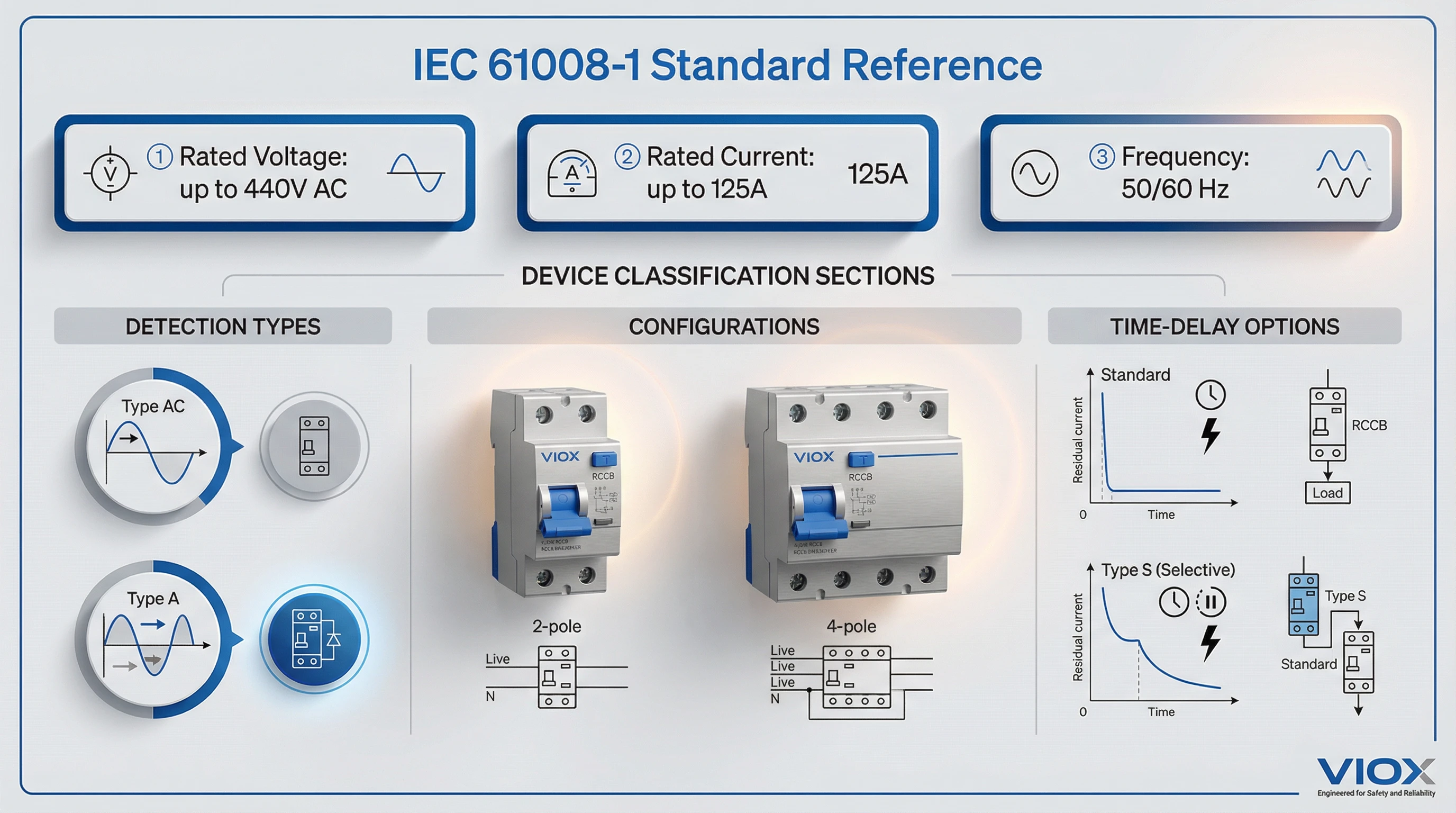
- 정격 작동 전압(Un): 최대 440V AC
- 정격 전류(In): 최대 125A
- 정격 주파수: 50Hz 또는 60Hz
장치는 일관된 잔류 전류 감도를 유지하면서 이러한 범위에서 작동해야 합니다. 이 표준은 기능적으로 독립적인 RCCB(외부 전원이 필요 없는 기계식 트립 메커니즘)와 라인 전압 종속 설계(작동하려면 공급 전압이 필요한 전자 RCCB)를 모두 수용합니다. 각 분류는 특히 전압 강하 또는 중단 시 동작에 대해 서로 다른 테스트 요구 사항을 트리거합니다.
IEC 61008-1에 따른 장치 분류
이 표준은 여러 차원에서 RCCB를 분류합니다.
AC 유형 대 A 유형 감지: IEC 61008-1은 두 가지 기본 감지 유형을 다룹니다. AC 유형 RCCB는 정현파 AC 잔류 전류(저항 부하에서 발생하는 기존 접지 오류 신호)에 응답합니다. A 유형 장치는 맥동 DC 잔류 전류(최신 전자 제품, LED 드라이버 및 가변 속도 기기에서 흔히 볼 수 있는 반파 정류 파형)에 대한 감도를 추가합니다. 두 유형 모두 표준의 테스트 조항에 자세히 설명된 특정 시간-전류 작동 곡선을 충족해야 합니다.
시간 지연 특성: 표준(순시) RCCB는 의도적인 지연 없이 트립됩니다. S 유형(선택적) RCCB는 시간 지연을 통합하여 다운스트림 장치가 먼저 오류를 제거할 수 있도록 합니다. 이는 배전 시스템에서 조정된 보호에 필수적입니다. 4조는 분류 프레임워크를 정의하고 9조는 해당 테스트 절차를 지정합니다.
극 구성: 이 표준은 2극(단상) 및 4극(3상) 구성을 다루며 각 토폴로지에 맞게 배선 및 테스트 요구 사항이 조정됩니다.
2024년 판 전환
2024년 11월 21일에 IEC는 통합된 3판(IEC 61008-1:2010+A1:2012+A2:2013)을 공식적으로 철회하고 4판을 발행했습니다. 이 전환은 10년 만에 가장 중요한 업데이트입니다. 주요 변경 사항은 다음과 같습니다.
- 표준 간 조화: 2024년 판은 IEC 61009(RCBO) 및 IEC 60755(일반 RCD 요구 사항)와 공유되는 모듈식 “블록 및 모듈” 구조를 채택합니다. 이러한 정렬은 모순을 줄이고 다중 표준 준수를 단순화합니다.
- 새로운 TOV 요구 사항: 8.17절 및 9.24절에서는 임시 과전압(TOV) 저항에 대한 필수 테스트를 도입합니다. 신재생 에너지 통합 및 그리드 불안정이 증가함에 따라 RCCB는 이제 과거 규범을 초과하는 과도 전압 스트레스에 직면합니다. TOV 테스트는 장치가 저하 또는 오작동 없이 전압 스파이크를 견딜 수 있는지 확인합니다.
- 개선된 유전체 테스트: 향상된 절차는 특히 민감한 제어 회로가 있는 전자 RCCB의 경우 실제 절연 스트레스를 더 잘 반영합니다.
- 단자 및 도체 참조: 이 표준은 이제 단자 설계 및 테스트에 대해 IEC 62873-3 시리즈를 참조하여 광범위한 저전압 개폐 장치 관행과의 일관성을 보장합니다.
2010+AMD 판에 따라 인증된 제조업체는 전환 기간에 직면합니다. 기존 인증서는 유효하지만 새로운 제출 및 재인증에는 2024년 요구 사항에 대한 테스트가 필요합니다. 조달 팀의 경우 특히 리드 타임이 길거나 다년 공급 계약이 있는 프로젝트의 경우 공급업체의 인증이 참조하는 판을 확인해야 합니다.
IEC 61008-1에서 다루지 않는 내용
경계를 이해하는 것도 똑같이 중요합니다.
- F 유형 및 B 유형 RCCB: 향상된 주파수 응답(EV 충전에서 일반적인 F 유형) 또는 전체 DC 잔류 전류 감지(태양광 인버터 및 VFD에 필요한 B 유형)를 위해 설계된 장치는 다음의 추가 요구 사항을 충족해야 합니다. IEC 62423. 해당 표준은 IEC 61008-1을 보완하며 F/B 유형 인증에 대해 동시에 적용됩니다.
- RCBO(과전류 + 잔류 전류 보호 결합): 많은 IEC 61008-1 조항을 참조하지만 과전류 조정 요구 사항을 추가하는 IEC 61009에 의해 규정됩니다.
- Application-specific installations: IEC 61008-1 defines product requirements. Installation practices, circuit design rules, and mandatory RCCB locations are covered by regional electrical codes (NEC Article 210.8 in North America, BS 7671 in the UK, DIN VDE in Germany).
Key Technical Requirements
IEC 61008-1 defines technical requirements through rated quantities—the values manufacturers declare and testing validates. These parameters govern everything from sensitivity thresholds to short-circuit withstand capacity.
Rated Quantities and Parameters
Every RCCB nameplate carries a set of rated values. Here’s what each means and why it matters:
Rated voltage (Un): The maximum operational voltage the RCCB is designed to handle continuously. Common values include 230V (single-phase residential), 400V/415V (three-phase industrial). The device must maintain specified performance across a voltage range, typically 85% to 110% of Un.
정격 전류(In): The maximum continuous load current the RCCB can carry without exceeding temperature-rise limits. Standard values include 16A, 25A, 32A, 40A, 63A, 80A, 100A, and 125A. This is NOT the trip current—it’s the thermal capacity for normal operation. The RCCB must pass In continuously while keeping contact temperature rise within limits specified in Clause 9.12.
Rated residual operating current (IΔn): The differential current that causes the RCCB to trip. This is the core safety parameter. Standard sensitivities include:
-sensitivity-levels-and-their-applications.webp)
- 10 mA: High-sensitivity protection for special applications (medical equipment, swimming pools)
- 30 mA: Personal protection standard for shock prevention (required for socket circuits in most codes)
- 100 mA: Fire protection in commercial/industrial installations
- 300 mA and 500 mA: Selective coordination in distribution systems, equipment protection
At exactly IΔn, the RCCB must reliably trip within specified time limits. IEC 61008-1 also defines IΔno (rated residual non-operating current)—the maximum leakage below which the device must NOT trip. For most RCCBs, IΔno = 0.5 × IΔn. This buffer prevents nuisance tripping from normal background leakage.
Rated making and breaking capacity (Im): The maximum prospective current the RCCB can safely close onto or interrupt under short-circuit conditions. Typical values: 500A, 1000A, 1500A, 3000A, 6000A, 10000A. This is NOT the rated short-circuit current (which requires upstream SCPD protection)—it’s the RCCB’s ability to operate its contacts under fault conditions without welding or exploding.
Rated residual making and breaking capacity (IΔm): Similar to Im, but for residual fault currents. The RCCB must trip and clear a ground fault even when the fault current approaches short-circuit levels. Standard values: 500A, 1000A, 1500A for residential devices; higher values for industrial applications.
Rated conditional short-circuit current (Inc) and rated conditional residual short-circuit current (IΔc): These define the maximum fault current the RCCB can withstand when protected by a specified short-circuit protective device (SCPD)—typically an upstream MCB or fuse. The coordination ensures the SCPD clears high-fault currents before the RCCB suffers damage. Clause 9.14 details the short-circuit coordination tests, which involve applying prospective currents up to Inc/IΔc and verifying the RCCB remains functional afterward.
Operating Characteristics and Time-Current Curves
IEC 61008-1 specifies precise time limits for tripping at various multiples of IΔn. These operating characteristics ensure consistent performance across manufacturers:
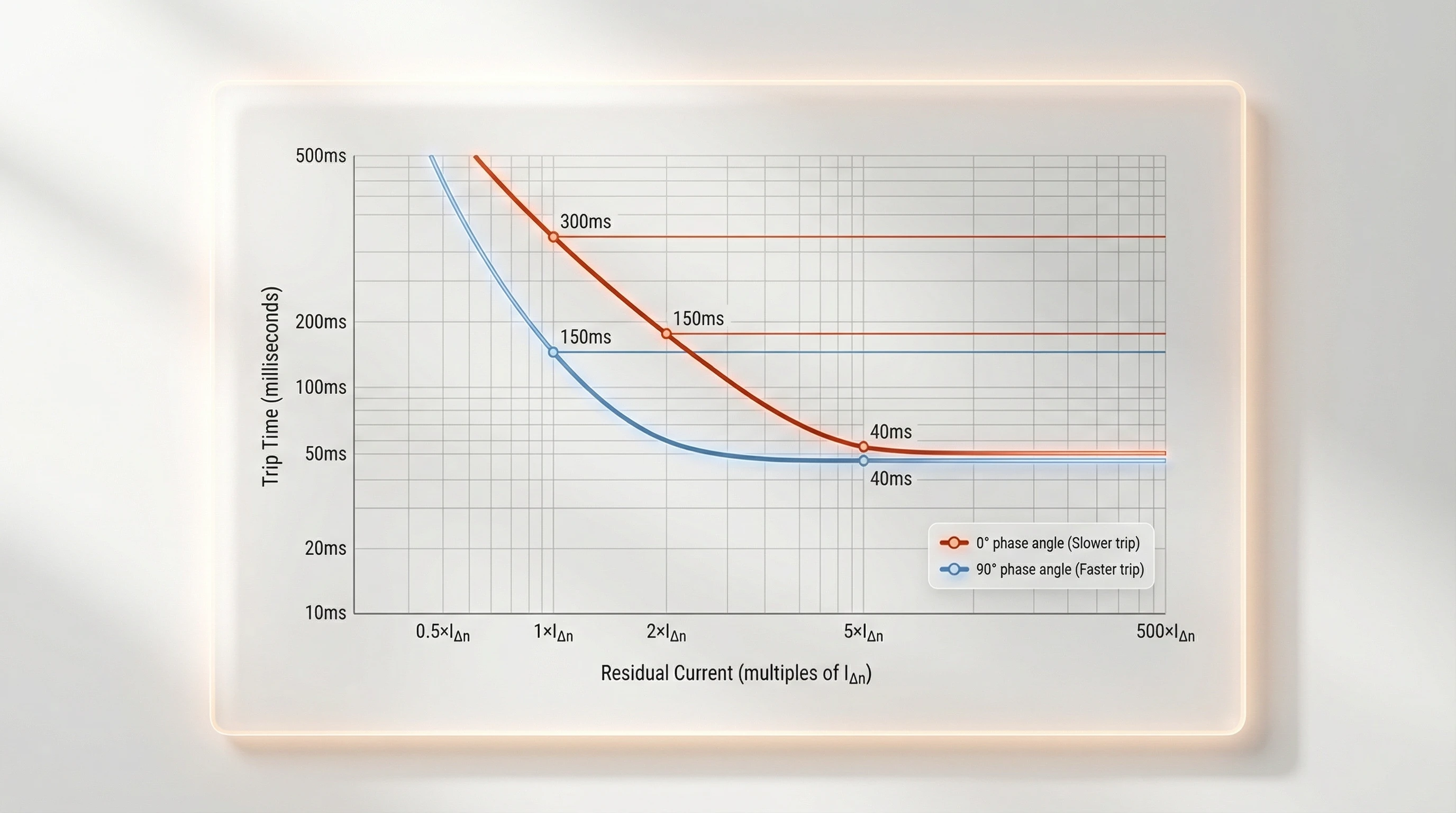
For Type AC and Type A RCCBs (sinusoidal AC residual current):
- 에서 IΔn (1x rated): Must trip within 300 ms at 0° phase angle; 150 ms at 90° phase angle
- 에서 2 × IΔn: Maximum 150 ms at 0°; 40 ms at 90°
- 에서 5 × IΔn: Maximum 40 ms at 0° and 90°
- 에서 500 × IΔn (high-current test): 40 ms maximum
The phase angle dependency reflects toroidal core behavior. Residual currents initiating at zero-crossing (0°) produce slower flux buildup than currents starting at peak (90°). The standard accounts for worst-case scenarios.
For Type A RCCBs with pulsating DC residual current: Additional limits apply when half-wave rectified currents (simulating electronic load faults) trigger the device. At IΔn with pulsating DC, maximum trip times are 300 ms (0°) and 200 ms (90°). These longer windows accommodate the fact that pulsating DC delivers energy to the toroidal core only during half-cycles.
Type S (selective) RCCBs: These incorporate intentional delays for coordination. Minimum non-operating times range from 130 ms to 500 ms at 2 × IΔn, allowing downstream instantaneous RCCBs to clear faults first. At 5 × IΔn or higher, Type S devices must still trip within 150 ms to ensure safety.
Non-actuating current limits: At 0.5 × IΔn (the IΔno threshold), the RCCB must remain stable for 2 hours in the most unfavorable position. This stability test, conducted at upper and lower temperature limits, ensures the device resists nuisance tripping from normal circuit leakage or harmonic currents.
Classification and Special Requirements
Surge immunity classification: The 2010+AMD and 2024 editions mandate surge withstand testing. RCCBs face two surge profiles:
- 0.5 μs / 100 kHz ring wave: Simulates fast transients from switching operations. RCCBs must withstand this without tripping or damage.
- 8/20 μs surge current: Standard impulse waveform up to 3000A peak. Tests verify the device doesn’t false-trip during lightning-induced surges or capacitor inrush.
DC component immunity (Type A requirement): Type A RCCBs must detect residual currents even when up to 6 mA of smooth DC current flows through the toroidal core. Smooth DC creates constant flux bias, potentially saturating the core and “blinding” the device to AC ground faults. Clause 9.9.4 tests this by superimposing 6 mA DC during normal operating characteristic tests—the RCCB must still trip within limits. This requirement prevents the hazardous scenario where rectified loads (washing machines, VFDs) leak DC and disable shock protection.
테스트 요구 사항
Clause 9 of IEC 61008-1 contains the heart of compliance: the type tests every RCCB design must pass before certification. These tests validate that rated quantities translate into real performance under stress—heat, humidity, mechanical shock, electrical transients, and short-circuit forces.
Type Testing Overview
Type testing is destructive, comprehensive, and performed on representative samples before mass production. The standard structures tests in families, each probing a different failure mode:
- Marking and construction: Verification that markings are permanent, terminals accept specified conductor sizes, and mechanical assemblies meet dimensional tolerances.
- Protection against electric shock: Dimensional checks with standard test fingers to ensure live parts remain inaccessible.
- Dielectric properties: Stresses insulation systems through humidity preconditioning, insulation resistance tests, and high-voltage impulse withstand tests (up to 8kV).
- Temperature-rise testing: Verifies that contact temperature rise stays within limits (typically max 50K) under continuous rated current.
- Operating characteristics: The centerpiece of functional testing, verifying trip times at various residual current levels, phase angles, and environmental extremes.
- Short-circuit behavior: Coordinated with an SCPD, the RCCB faces prospective currents up to Inc. It must not weld contacts or disintegrate.
- Endurance: 4,000 mechanical cycles and 2,000 electrical cycles to simulate years of field operation.
Specialized Tests (New and Enhanced Requirements)
Surge immunity testing: Two complementary tests address different transient threats. 0.5 μs / 100 kHz ring wave for switching transients, and 8/20 μs surge current (up to 3000A) for lightning-induced surges.
DC component testing for Type A: Type A RCCBs must demonstrate they can still trip on AC faults while 6 mA of smooth DC saturates the core.
Temporary Overvoltage (TOV) Resistance – NEW in 2024 Edition: The 2024 edition’s headline addition. RCCBs now face sustained overvoltage tests simulating grid disturbances. The RCCB must withstand 1.5 × Un for a specified duration without tripping or failure. This addresses field failures observed with renewable energy integration.
규정 준수 및 인증
Passing individual tests is necessary, but not sufficient. IEC 61008-1 structures compliance through annexes that define test sequencing, sample quantities, and ongoing verification.
Annex A: Test Sequences and Sample Counts
Annex A orchestrates the type test program. Typical certification requires 12-20 RCCB samples depending on the product range. Samples are divided into sequences (e.g., non-destructive, dielectric, short-circuit, endurance) to ensure thorough validation.
Annex D: Routine Tests for Production
Type testing validates the design. Routine tests validate every manufactured unit. Mandatory routine tests include dielectric strength, operating characteristic verification, and trip-free mechanism tests.
결론
IEC 61008-1 translates shock prevention from safety principle to engineered reality. The standard’s rated quantities define boundaries; its time-current curves ensure consistent sensitivity; its test protocols validate performance under stress. For manufacturers, it’s the blueprint for reliable design. For specifiers, it’s the common language bridging application requirements and product capabilities. For procurement teams, it’s the verification framework separating genuine compliance from marketing claims.
The 2024 edition reflects evolving electrical environments—renewable energy transients, electronic load proliferation, grid instability. Temporary overvoltage testing, harmonized structures, and enhanced dielectric validation ensure RCCBs keep pace with modern installations. As solar inverters, EV chargers, and variable-frequency drives become standard rather than exceptional, IEC 61008-1:2024 provides the foundation for protection that works not just in ideal lab conditions, but in the complex, transient-filled systems we’re actually building.
At VIOX Electric, IEC 61008-1 compliance isn’t a checkbox—it’s the starting point. Our VKL11, VML01B, and VKL11F series meet the 2024 edition requirements with margins verified through independent certification. We maintain full traceability from raw materials through production testing, backed by 20+ years of manufacturing experience and zero field failures traced to standard non-compliance.
Ready to specify IEC 61008-1 compliant RCCBs for your project?
연락처 our engineering team for technical consultation, test reports, and product selection guidance.
