
현대 전기 시스템에서 단락 고장은 수 밀리초 내에 막대한 에너지를 방출할 수 있습니다. 50,000암페어의 예상 고장 전류는 버스바를 구부릴 수 있을 만큼 강한 자기력, 구리 도체를 기화시킬 수 있을 만큼 강렬한 열 에너지, 그리고 작업자에게 위험을 초래하는 아크 플래시 위험을 발생시킵니다. 그러나 이러한 파괴적 영향 대부분은 예방 가능합니다.
전류 제한 회로 차단기는 회로 보호 기술의 근본적인 발전을 나타냅니다. AC 파형의 자연스러운 영점에서 고장을 차단하는 기존 차단기와 달리, 전류 제한 차단기는 고장 전류가 파괴적인 피크에 도달하기 전에 수 밀리초 내에 작동하여 고장 전류를 억제합니다. 이러한 신속한 개입은 전기 장비에 가해지는 기계적 및 열적 스트레스를 극적으로 감소시키고, 민감한 전자 장비를 손상으로부터 보호하며, 아크 플래시 위험을 상당히 완화합니다.
배전 시스템을 설계하는 전기 엔지니어, 보호 장치를 선정하는 패널 제조업자, 그리고 중요 인프라를 관리하는 시설 관리자에게 전류 제한 기술을 이해하는 것은 필수적입니다. 본 가이드는 전류 제한 회로 차단기의 작동 원리, 성능을 정의하는 주요 사양, 그리고 이 기술이 표준 회로 보호 대비 결정적 이점을 제공하는 시점에 대해 설명합니다.
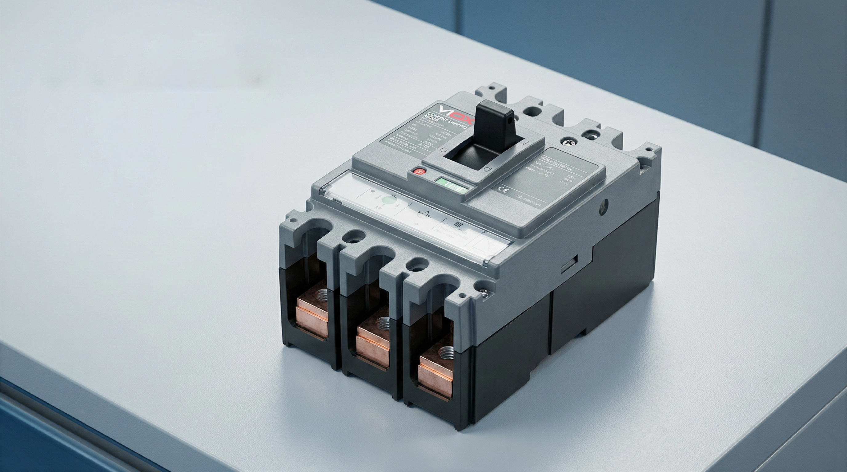
전류 제한 회로 차단기란 무엇인가?
전류 제한 회로 차단기는 단락 전류가 최대 예상 피크 값에 도달하기 전에 차단하도록 설계된 보호 장치입니다. 이 능력은 일반적으로 고장 전류가 완전한 피크에 도달한 후 자연 영점에서 차단하는 기존 회로 차단기와 구별됩니다.
전기 시스템에서 단락이 발생하면 전류는 극히 높은 비율로 상승하기 시작하여 수 밀리초 내에 수만 암페어에 도달할 수 있습니다. 표준 회로 차단기는 이 고장 상태를 감지하고 차단 메커니즘을 작동시키지만, 차단 과정에는 시간이 소요됩니다. 이 짧은 간격 동안 고장 전류는 완전한 예상 피크에 도달할 수 있으며, 이는 도체, 버스바 및 하류 장비에 스트레스를 주는 막대한 에너지를 방출합니다.
반면, 전류 제한 회로 차단기는 비범한 속도로 작동합니다. UL 489(몰드 케이스 회로 차단기에 대한 북미 표준)에 따르면, 회로 차단기는 반 사이클 미만(일반적으로 10밀리초 미만)으로 고장을 차단할 경우 “전류 제한”으로 인정됩니다. 이 신속한 응답은 높은 아크 전압을 발생시켜 시스템 전압에 반대하여, 효과적으로 전류 흐름을 억제하고 통과 피크 전류를 예상 고장 전류보다 훨씬 낮은 값으로 강제 감소시킵니다.
그 결과는 극적입니다: 예상 고장 전류가 50,000암페어 RMS 대칭값일지라도, 전류 제한 차단기는 실제 피크 전류를 15,000암페어 이하로 제한할 수 있습니다. 이 피크 전류 및 총 고장 에너지 감소는 그렇지 않았다면 발생했을 기계적 힘, 열 손상 및 아크 플래시 위험으로부터 하류 장비를 보호합니다.
전류 제한 회로 차단기의 작동 원리
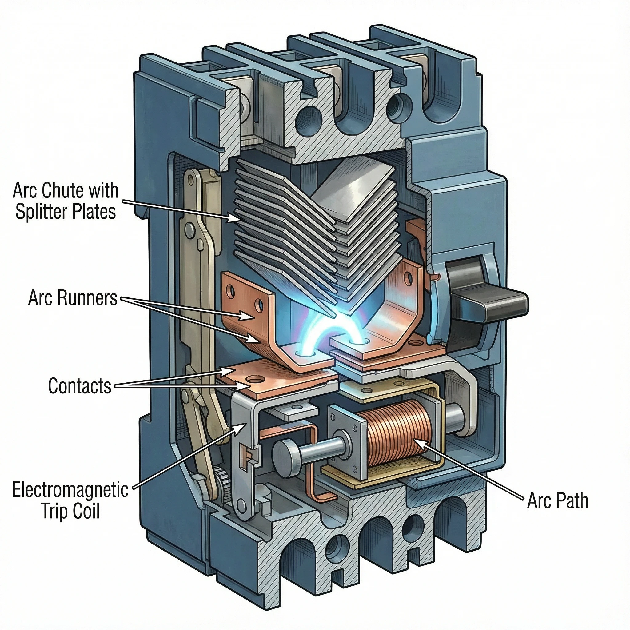
이러한 회로 차단기의 전류 제한 능력은 기계적 설계, 전자기 물리학 및 아크 관리를 신중하게 설계하여 결합한 결과입니다. 이 과정은 몇 가지 조정된 메커니즘을 통해 수 밀리초 내에 전개됩니다.
전기역학적 접점 분리
첫 번째 핵심 요소는 초고속 접점 분리입니다. 높은 고장 전류가 차단기의 접점을 통해 흐를 때, 이 전류에 의해 생성된 거대한 자기장은 강력한 전기역학적 힘을 생성합니다. 전류 제한 차단기는 이러한 힘을 활용하여 접점 분리를 보조하도록 접점 구성이 설계되어 있습니다. 즉, 자기장이 접점을 실제로 분리시키는 반발력을 생성하도록 접점이 배열됩니다.
이 “전기역학적 반발”은 더 높은 고장 전류가 실제로 접점 분리를 가속화함을 의미합니다. 차단기는 차단 메커니즘의 기계적 힘에만 의존하지 않습니다. 고장 전류 자체가 접점을 더 빠르게 개방하는 데 에너지를 기여합니다. 이는 고장 발생 후 1-2밀리초 이내에 이루어지는 극히 신속한 접점 분리를 보장합니다.
아크 형성 및 신장
접점이 고속으로 분리됨에 따라 간극에 전기 아크가 형성됩니다. 이 아크는 억제해야 할 문제라기보다는 전류 제한을 위한 주요 도구가 됩니다. 차단기의 내부 형상은 이 아크가 접점에서 빠르게 멀어지도록 하여 아크 슈트라고 불리는 특수 설계된 아크 챔버로 이동하도록 설계되어 있습니다.
Magnetic fields generated by the current flow and the physical shape of the arc runners guide the arc upward into the arc chute. As the arc moves and stretches, its length increases dramatically. A longer arc requires higher voltage to sustain it, and this arc voltage opposes the system voltage driving the fault current.
Arc Commutation and Splitting
The arc chute contains a series of metal plates arranged in a specific configuration (often V-shaped), called arc splitters or arc dividers. As the arc is driven into the chute, it contacts these plates and “commutates”—transferring from the main arc path to the splitter plates.
This process effectively splits the single high-energy arc into multiple smaller arcs in series. Each small arc develops its own voltage drop. If the arc chute contains, for example, 20 splitter plates, the total arc voltage can reach many times the system voltage. When the cumulative arc voltage exceeds the system voltage, the current is forced to decrease rapidly.
Arc Cooling and Extinction
The metal splitter plates also serve as heat sinks, rapidly cooling the arcs. The plates increase the arc’s surface area and conduct heat away. Combined with surrounding air or arc-quenching gases, this cooling reduces the arc’s conductivity.
The interplay of high arc voltage (opposing current flow) and arc cooling (reducing conductivity) forces the current toward zero. The breaker extinguishes the arc and clears the fault—all within a fraction of a cycle, before the fault current reaches its prospective peak.
This entire sequence—from fault detection through contact separation, arc elongation, splitting, and extinction—occurs in under 10 milliseconds. The current is interrupted not at a natural zero crossing but forcibly, by creating conditions where the arc cannot be sustained.
주요 기술 사양
Understanding current-limiting performance requires familiarity with three critical specifications that define how effectively a breaker limits fault current and protects downstream equipment.
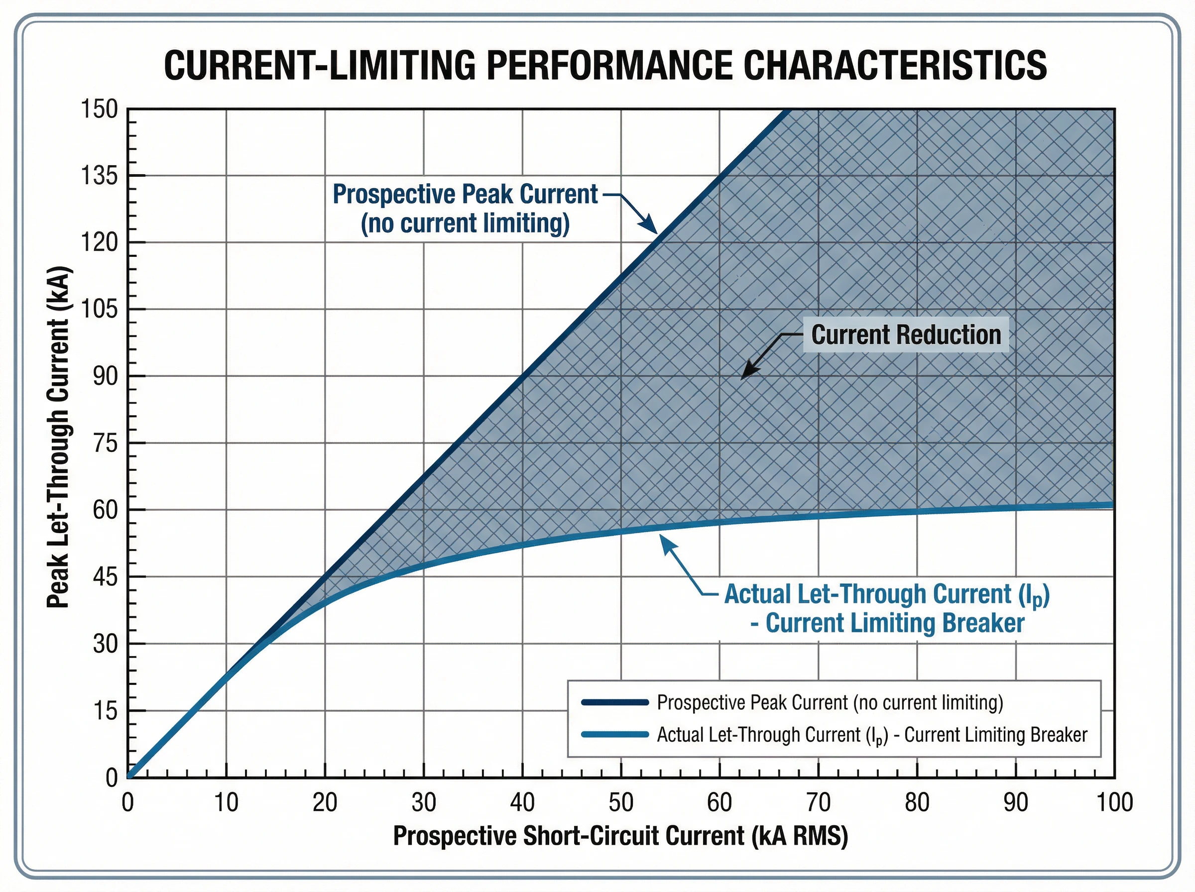
Let-Through Current (Ip)
그리고 let-through current (Ip) is the actual peak current that flows through the breaker during a fault, measured in amperes. This value represents the breaker’s current-limiting effectiveness: a lower Ip indicates better current limitation.
Manufacturers provide let-through current data in the form of characteristic curves. These graphs plot the peak let-through current (Ip) on the vertical axis against the prospective short-circuit current (RMS symmetrical amperes) on the horizontal axis. For any given prospective fault level at the installation point, the curve shows the maximum peak current that will actually flow.
For example, if the available fault current at a panelboard is 42,000 amperes RMS symmetrical, a current-limiting breaker might limit the actual peak current to just 18,000 amperes. This reduction from prospective to actual peak current protects busbars from bending, prevents conductor overheating, and reduces mechanical stress on all downstream components.
Thermal Stress (I²t)
그리고 I²t value (pronounced “I-squared-t”), measured in ampere-squared seconds (A²s), quantifies the thermal energy let through by the breaker during fault clearing. It represents the integral of the current squared over the total clearing time.
This specification is critical for protecting cables and sensitive electronic equipment. The insulation of cables has a specific thermal withstand rating expressed as I²t. If the protective device lets through more thermal energy than the cable can withstand, the insulation will be damaged even if the cable doesn’t physically melt.
Current-limiting breakers dramatically reduce I²t compared to standard breakers. For the same prospective fault current, a current-limiting device might have an I²t value 50-80% lower than a conventional breaker. This reduced thermal stress prevents conductor damage, protects cable insulation, and extends equipment life.
Manufacturers provide I²t curves similar to let-through current curves, showing the maximum thermal energy as a function of prospective fault current. Some standards define energy-limiting classes for circuit breakers based on their I²t performance.
Breaking Capacity (Icu and Ics)
그리고 단 용량 defines the maximum fault current the breaker can safely interrupt. Two ratings are relevant under IEC 60947-2 (the international standard for low-voltage circuit breakers):
- 최대 차단 용량(Icu): The maximum fault current the breaker can interrupt without being destroyed. After interrupting a fault at Icu level, the breaker may not be suitable for continued service and might require replacement. This represents the breaker’s absolute upper limit.
- 서비스 차단 용량(Ics): The maximum fault current the breaker can interrupt multiple times while remaining fully functional and reliable for continued service. Ics is expressed as a percentage of Icu (typically 50%, 75%, or 100%). For critical applications requiring high reliability, breakers with Ics = 100% Icu are preferred.
The fundamental selection rule is straightforward: the breaker’s Icu must be equal to or greater than the prospective short-circuit current at the point of installation. Current-limiting breakers can achieve high breaking capacities (50kA, 85kA, or higher) in compact form factors because the current-limiting action itself reduces the energy the breaker must handle.
The Interrelationship of Specifications
These specifications work together to define protection performance. When a fault occurs up to the breaker’s Icu rating, the current-limiting action reduces both the peak current (Ip) and the total thermal energy (I²t) to values far below what the prospective fault would produce. This coordinated reduction in peak mechanical stress and thermal damage is what makes current-limiting breakers essential for protecting modern electrical systems with high available fault currents.
Standards and Compliance
Current-limiting circuit breakers are governed by rigorous international and regional standards that define performance requirements, testing procedures, and safety criteria.
IEC 60947-2: International Standard
IEC 60947-2 is the international standard for low-voltage circuit breakers used in industrial and commercial applications. This comprehensive standard establishes:
- Performance categories: The standard distinguishes between Category A breakers (no intentional short-circuit time delay) and Category B breakers (with short-time withstand capability). Most modern current-limiting MCCBs are Category A devices.
- Breaking capacity verification: IEC 60947-2 specifies rigorous test sequences to verify both ultimate breaking capacity (Icu) and service breaking capacity (Ics). These tests involve multiple making and breaking operations under specified fault conditions.
- Current-limiting performance: While the standard doesn’t mandate current limitation, it provides test procedures to verify and document let-through current and I²t performance for breakers claiming current-limiting capability.
- Coordination and selectivity: The standard establishes requirements for back-up protection (cascading), where a current-limiting breaker upstream protects a downstream breaker with lower breaking capacity than the prospective fault current at its location.
UL 489: North American Standard
UL 489 is the Underwriters Laboratories standard for molded case circuit breakers in North America. Key provisions include:
- Current-limiting definition: UL 489 specifies that a circuit breaker qualifies as “current limiting” if it clears a fault in less than half a cycle (typically under 10 milliseconds for 60 Hz systems).
- Let-through testing: The standard requires extensive testing to generate let-through current curves that show the actual peak current as a function of prospective fault current.
- Short-circuit ratings: UL 489 defines interrupting ratings (IR) and establishes test procedures to verify breaker performance at rated voltage and current levels.
규정 준수 및 인증
For electrical system designers and specifiers, standards compliance ensures:
- Verified performance: Certified breakers have undergone rigorous third-party testing to confirm their current-limiting capability and breaking capacity.
- Design confidence: Engineers can rely on published let-through curves and I²t data for equipment protection analysis and arc flash calculations.
- Regulatory acceptance: Standards-compliant breakers meet electrical code requirements in their respective markets (IEC zones or North American installations).
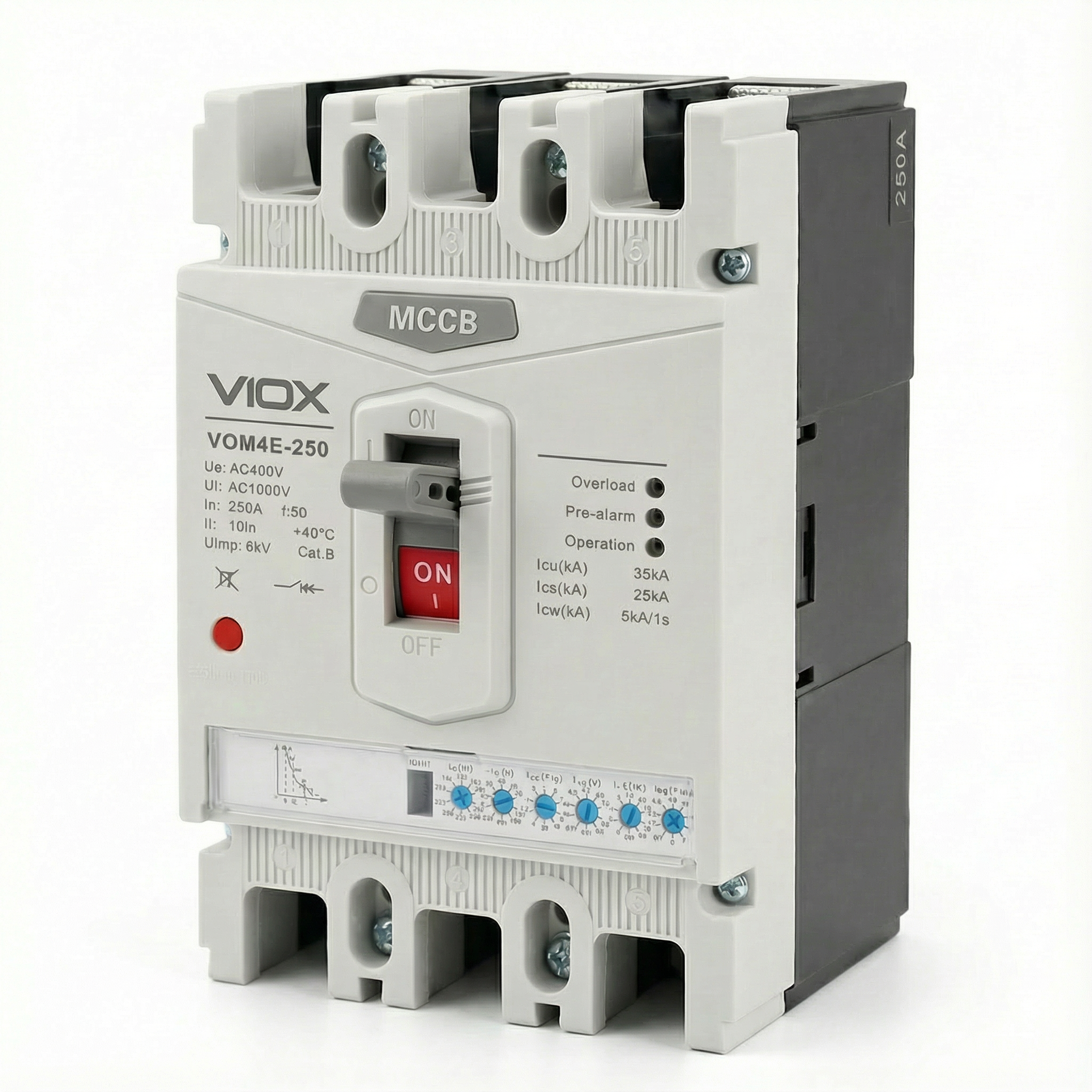
VIOX current-limiting circuit breakers are designed and tested to meet both IEC 60947-2 and UL 489 requirements, ensuring global applicability and verified protection performance.
응용 프로그램 및 사례
Current-limiting circuit breakers deliver critical benefits in electrical systems where high available fault currents threaten equipment integrity and personnel safety.
Data Centers and Critical IT Infrastructure
Modern data centers face extraordinary fault current challenges. High-density server racks, powerful UPS systems, and multiple utility feeds create available fault currents that can exceed 65kA or more. Current-limiting breakers are essential in these environments:
- IT equipment protection: Servers, storage arrays, and networking gear contain sensitive electronics vulnerable to even brief overcurrent events. Current-limiting breakers reduce the fault energy to levels that prevent component damage.
- 선택적 조정: Data center reliability depends on isolating faults without cascading outages. Current-limiting breakers facilitate coordination between upstream and downstream protection, ensuring only the affected circuit trips.
- Arc flash mitigation: Maintenance personnel work on energized equipment regularly. By reducing peak fault current and clearing time, current-limiting breakers dramatically lower arc flash incident energy, improving worker safety and potentially reducing PPE requirements.
- Compact installations: Current-limiting technology enables high breaking capacity (50kA-100kA) in compact MCCBs, supporting dense power distribution without requiring oversized switchgear.
Industrial Manufacturing Facilities
Industrial plants with large motors, transformers, and extensive distribution networks face fault currents that can damage production equipment:
- 모터 제어 센터: Protecting motor starters, variable frequency drives, and control electronics from fault current stress. Current-limiting breakers prevent damage to expensive drive electronics and ensure production continuity.
- High-capacity feeders: Where multiple power sources or large transformers create fault currents exceeding 50kA, current-limiting breakers provide protection without requiring expensive high-interrupting-capacity switchgear throughout the system.
- 장비 보호: Busbars, cable trays, and panel components have mechanical strength limits. Current-limiting breakers reduce the magnetic forces during faults, preventing physical damage to distribution infrastructure.
Commercial Buildings with High Power Density
Office towers, hospitals, and retail centers increasingly deploy high-power systems:
- Main and sub-main distribution: Current-limiting breakers on main service entrances and distribution boards protect against utility-supplied fault currents while enabling effective downstream coordination.
- 비상 전원 시스템: Generator and transfer switch protection where multiple sources increase available fault current.
- Renovation and expansion: Adding capacity to existing buildings often increases fault current levels. Current-limiting breakers can sometimes eliminate the need for complete system upgrades by providing adequate protection within existing infrastructure ratings.
Cascading Protection (Back-Up Protection)
One of the most valuable applications is enabling cascading or series rating. A current-limiting breaker installed upstream can protect downstream breakers with lower breaking capacity than the prospective fault current at their location. This allows:
- 비용 최적화: Using less expensive, lower-rated breakers downstream while maintaining full protection.
- Simplified specification: Standardizing on common breaker types throughout the facility while the current-limiting main breaker provides system-wide protection.
- System flexibility: Adding circuits or loads without necessarily upgrading all downstream protection devices.
Current Limiting vs Standard Circuit Breakers
Understanding the distinction between current-limiting and standard circuit breakers clarifies when each technology is appropriate.
Interruption Method
Standard Breakers: Conventional circuit breakers detect a fault and initiate the trip mechanism, but allow the fault current to rise to its prospective peak value. Interruption occurs at or near a natural current zero crossing, typically after 0.5 to 1.5 cycles (8-25 milliseconds at 60 Hz). During this time, the full fault current stresses the system.
Current-Limiting Breakers: These devices act within milliseconds to forcibly interrupt the current before it reaches its prospective peak. Through electrodynamic contact separation and arc voltage build-up, they clear the fault in less than half a cycle (under 10 milliseconds), dramatically reducing both peak current and total fault energy.
Peak Current and Mechanical Stress
Standard Breakers: The full prospective fault current flows, creating maximum magnetic forces. For a 50kA prospective fault, the full 50kA (70kA peak asymmetrical) generates enormous mechanical stress on busbars, terminals, and connections.
Current-Limiting Breakers: The let-through current is significantly reduced. For the same 50kA prospective fault, a current-limiting breaker might limit the actual peak to 15-20kA, reducing magnetic forces by 60-70%.
Thermal Energy (I²t)
Standard Breakers: Longer clearing time and higher peak current result in substantial thermal energy release. Cables, busbars, and connections absorb significant heat, potentially damaging insulation.
Current-Limiting Breakers: Reduced peak current and ultra-fast clearing dramatically lower I²t values, often by 50-80%. This protects cable insulation, prevents conductor annealing, and safeguards sensitive electronics from thermal stress.
Arc Flash Incident Energy
Standard Breakers: Higher fault current and longer clearing time increase arc flash incident energy, requiring higher-level PPE and creating greater safety hazards for maintenance personnel.
Current-Limiting Breakers: Reduced fault current magnitude and duration significantly decrease arc flash energy. This can lower the arc flash boundary, reduce PPE requirements, and improve overall electrical safety.
Cost and Complexity Trade-offs
Standard Breakers: Generally less expensive per unit. Suitable for applications where fault currents are moderate and equipment ratings adequately exceed available fault levels.
Current-Limiting Breakers: Higher initial cost, but can reduce total system cost by:
- Allowing lighter-duty downstream components
- Enabling cascading protection with lower-rated breakers
- Reducing panel reinforcement requirements
- Protecting expensive equipment from damage
- Lowering arc flash mitigation costs
각 유형을 선택하는 시기
Choose Standard Breakers when:
- Available fault current is well below the system’s short-circuit rating
- Budget constraints are paramount and fault levels don’t justify current-limiting protection
- Coordination can be achieved without current limitation
Choose Current-Limiting Breakers when:
- Available fault currents exceed 20-25kA
- Protecting sensitive electronic equipment (data centers, control systems)
- Seeking arc flash hazard reduction
- Enabling cascading protection to reduce costs
- Facility expansion has increased fault levels beyond original equipment ratings
선택 기준
Selecting the right current-limiting circuit breaker requires evaluating several technical and application factors.
Calculate Available Fault Current
The first step is determining the prospective short-circuit current at the installation point. This requires:
- Utility transformer capacity and impedance
- Conductor lengths and sizes
- Impedance of distribution components
- 모터 및 발전기의 기여
많은 유틸리티에서 고장 전류 데이터를 제공하거나 자격을 갖춘 전기 엔지니어가 산업 표준 방법(IEC 60909 또는 IEEE 표준)을 사용하여 단락 회로 계산을 수행할 수 있습니다. 차단기의 궁극적인 차단 용량(Icu)은 이 계산된 고장 전류 이상이어야 합니다.
장비 보호 요구 사항 평가
보호해야 할 사항 고려:
- 민감한 전자 제품데이터 센터, 제어 시스템 및 통신 장비는 통과 전류 및 I²t 감소로 상당한 이점을 얻습니다.
- 버스바 및 도체 정격고장 전류가 버스바, 케이블 또는 패널 구성 요소의 단락 회로 내전압 정격에 접근하거나 초과하는 경우 전류 제한이 필수적입니다.
- 기존 장비시설을 확장할 때 전류 제한 차단기는 전체 교체 없이 기존 인프라를 보호할 수 있습니다.
아크 플래시 위험 완화 요구 사항 평가
아크 플래시 연구에서 광범위한 PPE가 필요하거나 용납할 수 없는 작업자 위험을 초래하는 높은 사고 에너지 수준을 나타내는 경우 전류 제한 차단기는 아크 플래시 에너지를 크게 줄일 수 있습니다. 전류 제한이 위험 범주를 낮추고 안전을 개선하는지 확인하려면 아크 플래시 계산을 검토하십시오.
조정 요구 사항 고려
선택적 조정(고장에 가장 가까운 차단기만 트립되도록 보장)은 많은 응용 분야에서 중요합니다.
- 캐스케이드 보호다운스트림 차단기의 차단 용량이 사용 가능한 고장 전류보다 낮은 경우 업스트림 전류 제한 차단기가 백업 보호를 제공할 수 있습니다.
- 중요 부하데이터 센터, 병원 및 산업 공정에서는 불필요한 중단 없이 고장 격리가 필요합니다. 전류 제한 차단기는 통과 에너지를 줄여 조정을 용이하게 합니다.
통과 전류 곡선 검토
제조업체는 전류 제한 차단기에 대한 통과 전류(Ip) 및 I²t 곡선을 제공합니다. 이러한 곡선을 다음 사항과 비교하십시오.
- 장비 내전압 정격
- 케이블 I²t 제한
- 아크 플래시 에너지 감소 목표
- 다운스트림 장치와의 조정 요구 사항
표준 준수 확인
차단기가 해당 표준을 충족하는지 확인하십시오.
- IEC 60947-2 국제/산업 응용 분야의 경우
- UL 489 북미 설치의 경우
- 지역 전기 규정 및 인증 요구 사항
결론
전류 제한 회로 차단기는 현대 전력 시스템에서 높은 고장 전류라는 근본적인 문제를 해결하는 전기 보호 기술의 중요한 발전입니다. 밀리초 단위로 고장을 차단하고 피크 통과 전류와 열 응력을 크게 줄임으로써 이러한 장치는 값비싼 장비를 보호하고 인력 안전을 개선하며 보다 유연한 시스템 설계를 가능하게 합니다.
고전력 배전 시스템(특히 25kA를 초과하는 고장 전류가 있는 데이터 센터, 산업 시설 및 상업용 건물)을 사용하는 전기 엔지니어 및 시설 관리자의 경우 전류 제한 기술은 장비 보호, 아크 플래시 완화 및 조정 유연성에서 측정 가능한 이점을 제공합니다. 주요 사양(통과 전류 Ip, 열 응력 I²t 및 차단 용량 Icu)은 보호 성능을 확인하고 안전하고 안정적인 작동을 보장하는 데 필요한 엔지니어링 데이터를 제공합니다.
VIOX Electric은 IEC 60947-2 및 UL 489 표준에 따라 설계된 전류 제한 회로 차단기를 제조하여 35kA에서 100kA까지의 차단 용량과 포괄적인 통과 성능 곡선을 제공합니다. 기술 사양, 응용 프로그램 지침 또는 특정 보호 요구 사항에 대해 논의하려면 VIOX의 엔지니어링 팀에 문의하십시오.
검증된 전류 제한 기술로 중요한 인프라를 보호하십시오. VIOX Electric에 문의 회로 보호 요구 사항에 대해 논의합니다.
