នៅលើទំព័រនេះ
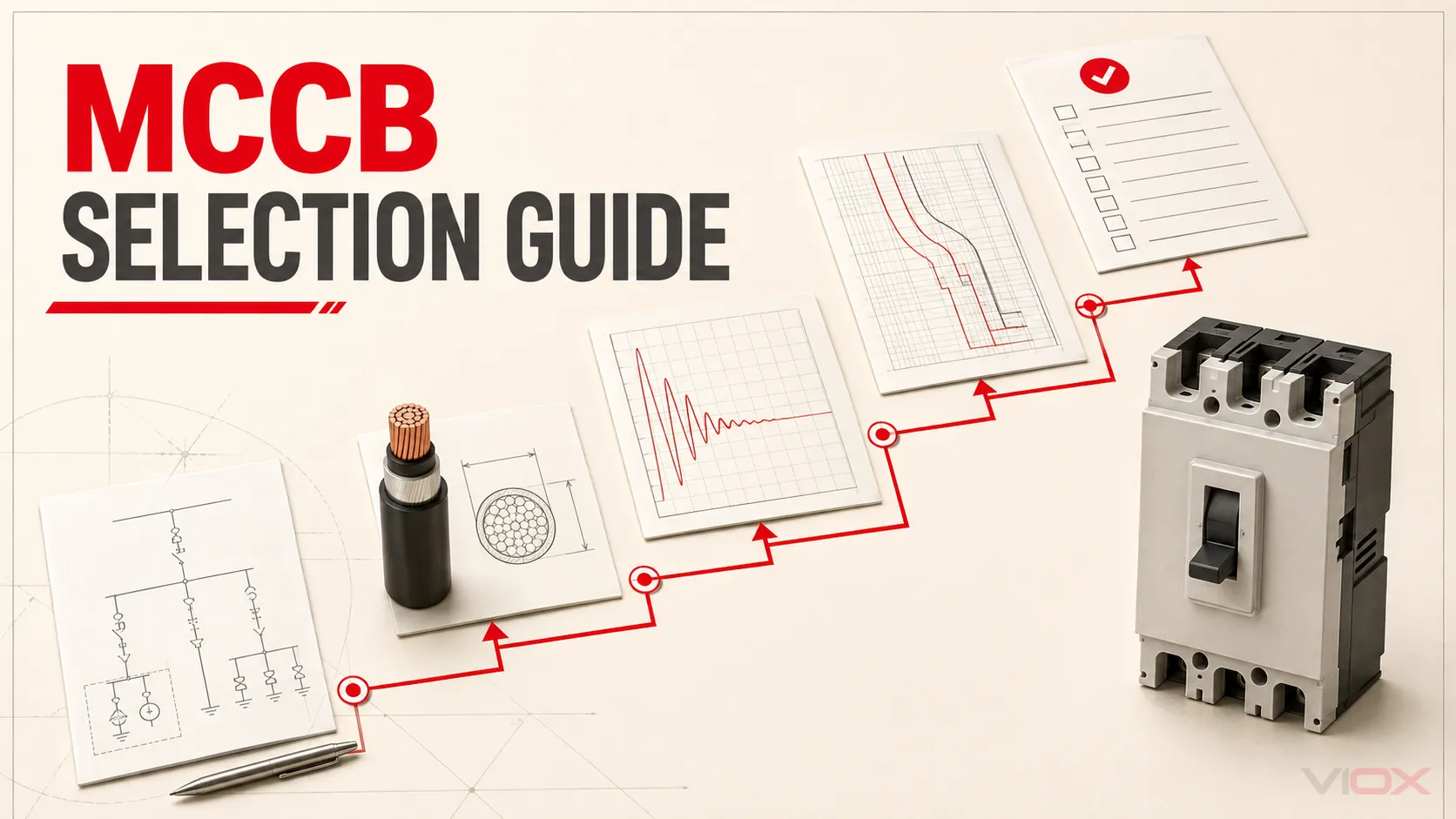
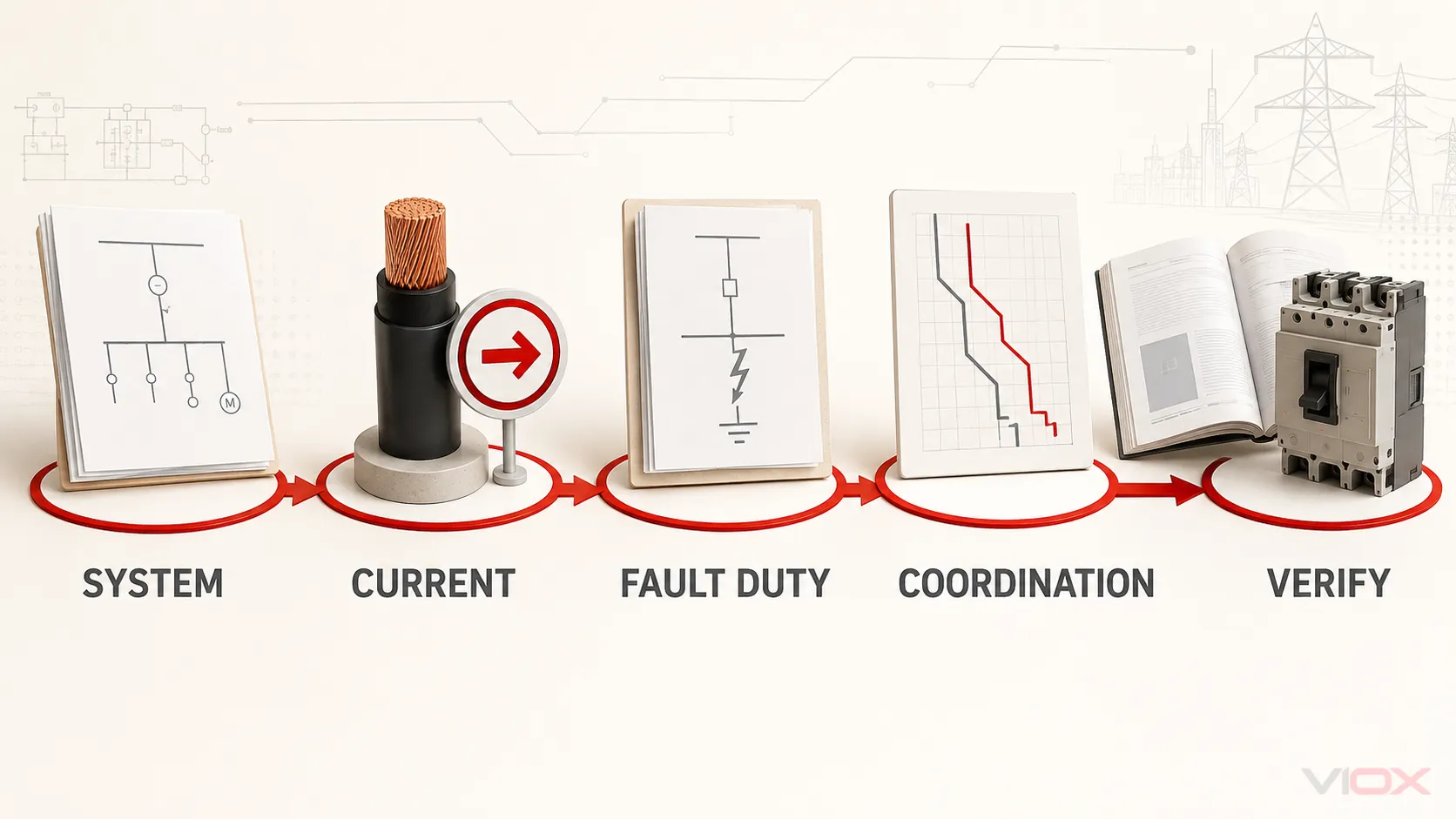
Do not select a molded case circuit breaker (MCCB) from load current alone. First define the system voltage and frequency, AC or DC duty, design current, conductor ampacity, prospective short-circuit current at the installation point, load starting behavior, coordination objective, pole and neutral requirements, environment, mounting, terminals, and accessories. Then choose a candidate whose published ratings satisfy every input at the same time.
The result should be a specification, not just an ampere value: applicable standard, number of poles, frame and trip arrangement, rated operational voltage, current or long-time setting range, Icu and Ics at that voltage, trip functions, mounting, terminals, and required accessories. Verify the exact combination in the manufacturer’s current catalogue, time-current curves, coordination tables, and installation instructions before release.
ច្បាប់ជ្រើសរើស: calculate what the circuit requires, then verify what the exact breaker can deliver. A familiar frame size, a higher ampere label, or a large kA number cannot substitute for the other checks.
MCCB Selection Input Sheet
Complete this sheet before opening a product catalogue. A blank field is an unresolved design input, not permission to guess.
| បញ្ចូល | អ្វីដែលត្រូវកត់ត្រា | Why it changes the MCCB specification |
|---|---|---|
| ប្រព័ន្ធ | AC or DC; nominal and maximum operating voltage; phase arrangement; frequency | Ratings can change with voltage, current type, frequency, and pole configuration |
| កាតព្វកិច្ចសៀគ្វី | Incomer, feeder, motor feeder, generator, capacitor bank, transformer secondary, or other load | Starting current, harmonics, duty cycle, and protection objectives differ |
| Design current, Ib | Calculated demand with the load profile and applicable installation rules | Establishes the current the circuit must carry in normal service |
| Conductor limit, Iz | Allowable conductor current after installation correction factors | Prevents the breaker from leaving the conductor inadequately protected |
| កម្រិតកំហុស | Maximum prospective short-circuit current at the MCCB terminals for every credible source configuration | Establishes required breaking performance at the actual point of installation |
| Continuity objective | Required selectivity, backup/cascading arrangement, and acceptable post-fault service condition | Changes Ics, trip functions, time delays, and approved device combinations |
| Ground and neutral strategy | Earthing arrangement; distributed neutral; neutral loading; conductors to switch and protect | Determines poles, neutral treatment, and possible ground-fault functions |
| បរិស្ថាន | Enclosure internal temperature, altitude, grouping, ventilation, humidity, pollution, vibration, and frequency | Can affect current carrying, tripping, dielectric performance, and interruption capability |
| Mechanical interface | Fixed, plug-in, or withdrawable arrangement; panel cut-out; busbar/cable connection; terminal orientation | Determines fit, terminals, barriers, and installation accessories |
| ចំណុចប្រទាក់បញ្ជា | Auxiliary contact, alarm contact, shunt trip, undervoltage release, motor operator, interlock, or communication | Accessory voltage, capacity, compatibility, and panel wiring must be specified |
| ភស្តុតាង | Applicable standard, project specification, manufacturer catalogue revision, curves, and coordination tables | Makes the final decision traceable and reviewable |
If the required data are not yet available, the MCCB can be shortlisted but not finally selected. A ឧបករណ៍គណនាទំហំឧបករណ៍បំបែកសៀគ្វី may help with an initial load-current check, but it cannot determine the site’s fault level, conductor installation corrections, coordination, or exact catalogue combination.
Step 1: Define the Circuit Before Choosing a Frame
Record the complete source and load context. At minimum, identify:
- maximum operating voltage, not only the nominal system label;
- AC or DC duty and system frequency;
- phase arrangement and conductors that require simultaneous switching;
- the load profile, including continuous duty, cyclic duty, starting current, transformer energization, or other transient behavior;
- source configurations that can increase fault current, such as parallel transformers, generators, or closed bus ties;
- the applicable product standard, installation rules, panel-assembly requirements, and project specification.
For an IEC-oriented industrial installation, IEC 60947-2:2024 is the current circuit-breaker product standard. Its scope covers circuit-breakers intended for operation by instructed or skilled persons, with rated voltages not exceeding 1,000 V AC or 1,500 V DC. That scope does not by itself prove that a particular MCCB is suitable for a project; the exact product declarations and the applicable installation and assembly requirements still control.
AC and DC ratings are not interchangeable. DC arc interruption may require a specific pole arrangement or series connection defined by the manufacturer. Do not construct a DC pole scheme from a generic diagram or assume that an AC voltage rating applies to DC.
Step 2: Coordinate Load Current, Conductors, Trip Rating, and Frame
Start with the circuit design current, Ib, calculated from the actual load data and the rules applicable to the project. For a balanced three-phase load, an initial current calculation may use:
Ib = P / (√3 × U × PF × η)កន្លែងណា ទំ is real input or output power as defined for the calculation, U is line-to-line voltage, PF គឺកត្តាថាមពល (Power factor) និង η is efficiency when the stated power is on the output side of the equipment. For an unbalanced or harmonic-rich load, calculate phase and neutral currents from the real load schedule rather than relying on this simplified expression.
The familiar coordination relationship is:
Ib ≤ In (or the effective long-time current setting) ≤ IzUse it as a screening relationship, not as the whole design. The applicable installation rules determine how continuous loads, motors, correction factors, parallel conductors, neutral current, and overload protection are handled. There is no universal rule that every MCCB should simply be selected at 125% of load current.
Keep the four current-related values separate
| ធាតុ | Meaning in the selection process | អ្វីដែលត្រូវផ្ទៀងផ្ទាត់ |
|---|---|---|
| Design current, Ib | Calculated current demanded by the circuit | Load schedule, diversity, duty, starting behavior, and governing calculation method |
| Conductor limit, Iz | Permissible current for the installed conductor system | Material, insulation, installation method, grouping, ambient, harmonics, and terminals |
| Breaker current or long-time setting | Current basis used by the trip unit for overload protection | Rating plug or sensor rating, setting range, curve, tolerances, and whether the setting protects Iz |
| ទំហំស៊ុម (Frame size) | Mechanical platform and maximum family capability | Compatible trip units, interruption ratings, dimensions, terminals, and accessories |
A 250 A frame does not automatically mean a 250 A protection setting. Depending on the product family, the frame may accept a lower-current trip unit, rating plug, or adjustable long-time setting. Conversely, turning down an adjustable setting does not automatically make every larger frame suitable: cable terminals, minimum sensor/rating ranges, time-current behavior, enclosure heating, and coordination still require verification.
For available preferred ratings after the calculation, use the standard breaker sizes reference. Treat that page as a rating lookup, not evidence that a particular frame or conductor is correct.
Step 3: Match Fault Duty to Icu, Ics, and the Panel Assembly
Obtain the ចរន្តខ្លីសៀគ្វីអតិបរមាដែលអាចកើតមាន at the MCCB’s actual installation point. Use a project short-circuit study or another method accepted for the installation. Include credible operating configurations; a value calculated for one transformer with an open bus tie may not cover a future or alternate parallel-source condition.
For an IEC 60947-2 candidate, verify the published rated ultimate short-circuit breaking capacity (Icu) at the actual operational voltage. The selected Icu must not be below the prospective fault current unless a specifically tested and documented backup or cascading arrangement applies.
Also evaluate rated service short-circuit breaking capacity (Ics). Ics and Icu are separate catalogue ratings, and Ics may be expressed as a percentage of Icu. Schneider Electric’s manufacturer explanation of Icu and Ics emphasizes that the exact values must be read from the relevant product catalogue. Do not assume that every MCCB has Ics = Icu, and do not choose an Ics percentage from a generic building type.
Breaking-capacity screen
| ពិនិត្យ | លក្ខខណ្ឌឆ្លងកាត់ | ភស្តុតាង |
|---|---|---|
| Voltage basis | The Icu and Ics values are stated for the actual Ue and AC/DC duty | Exact catalogue row and product marking |
| Maximum fault current | Icu covers the prospective short-circuit current at the installation point | Current short-circuit study and operating scenario |
| Service continuity | Ics meets the project’s post-fault service objective | Project specification and exact catalogue value |
| Backup or cascading | The upstream/downstream combination is explicitly published for the voltage and fault level | Manufacturer combination table; never an extrapolation |
| Assembly capability | The complete panel or switchboard short-circuit rating is adequate | Assembly design verification and panel documentation |
The MCCB’s breaking capacity does not establish the short-circuit rating of the completed panel. IEC 61439-1:2020 sets general construction, service-condition, technical-characteristic, and verification requirements for low-voltage assemblies, while IEC 61439-2:2020 covers power switchgear and controlgear assemblies. Busbars, supports, connections, enclosures, protective devices, and the verified device combination all contribute to assembly performance. A 50 kA breaker installed in an assembly verified for a lower fault level does not make the assembly a 50 kA panel.
Step 4: Choose the Trip Unit Around the Protection Objective
Select trip technology only after the load and coordination objectives are clear.
| តម្រូវការ | Thermal-magnetic may be sufficient when | Electronic trip becomes relevant when |
|---|---|---|
| ការផ្ទុកលើសទម្ងន់ និងការការពារសៀគ្វីខ្លី | Published fixed or limited-adjustment curves fit the conductor and load | Wider long-time and short-time adjustment is needed |
| ចរន្តពេលចាប់ផ្តើម (Inrush current) | The manufacturer’s curve clears normal transients while protecting the circuit | Multiple pickup and delay settings are needed to shape the response |
| ការជ្រើសរើស | Published combinations meet the required discrimination range | Adjustable short-time delay, ground-fault, or zone-selective functions are required |
| Monitoring or communication | No metering or remote data is required | The project needs supported measurement, alarms, communications, or event data |
| Change management | The circuit duty is stable and the fixed configuration is documented | A controlled adjustment range is needed for a defined future operating envelope |
Electronic is not automatically “better,” and thermal-magnetic is not automatically “simpler to coordinate.” The correct choice is the one whose published time-current behavior, tolerances, functions, environmental limits, and accessory ecosystem meet the project.
Coordination cannot be proven by comparing ampere ratings alone. Overlay time-current curves and use manufacturer selectivity or backup tables for the exact upstream and downstream devices. ABB’s low-voltage selectivity documentation illustrates why selectivity depends on defined techniques and device combinations. If adjustable protection is selected, record who owns the settings study and commissioning values. The separate MCCB trip-unit settings guide explains Ir, Isd, Ii, and related functions; this selection page does not replace that settings study.
For the technology decision itself, compare thermal-magnetic and electronic trip MCCBs before fixing the trip-unit type in the specification.
Step 5: Specify Poles, Neutral Treatment, and Accessories
Choose the number of poles from the distribution system and the required switching and protection functions. Record which conductors are phases, neutral, grounded conductors, and protective conductors; then verify the breaker’s permitted application.
- A three-phase circuit may require three or four switching poles depending on the system and applicable rules.
- A distributed neutral does not automatically mean that every project needs the same neutral protection arrangement.
- Harmonic-rich loads can change neutral-current assumptions and must be assessed in the conductor and protection design.
- Ground-fault or earth-fault protection functions must be selected and coordinated within the system’s earthing architecture.
- Protective conductors are not treated as ordinary switched current-carrying poles.
For DC applications, follow only manufacturer-published DC voltage, polarity, and pole-connection instructions for the exact device. Eaton’s MCCB application guide likewise treats pole count as a distribution-system decision and notes that some DC applications use special multipole configurations.
Specify accessories as part of the breaker catalogue number, not as an afterthought. For each shunt trip, undervoltage release, auxiliary contact, alarm contact, motor operator, rotary handle, interlock, communication module, or residual/ground-fault accessory, record control voltage, contact duty, mounting position, compatibility, and quantity. Verify that internal accessory slots and external dimensions support the complete combination.
Step 6: Check the Real Panel Environment and Mechanical Interface
MCCBs are usually selected from catalogue conditions but operate inside an enclosure. Check the manufacturer’s tables and instructions for the exact family against:
- panel internal ambient temperature and heat from adjacent devices;
- altitude and its effect on cooling or dielectric performance;
- 50/60 Hz or another specified frequency;
- fixed, plug-in, or withdrawable mounting and orientation;
- grouping, ventilation, clearances, barriers, and terminal shields;
- cable or busbar material, cross-section, lug range, number of conductors, and terminal orientation;
- enclosure space for handle mechanisms, interlocks, motor operators, and cable bending;
- environmental exposure such as humidity, pollution, vibration, and corrosion.
Do not use one generic derating table for every MCCB. Eaton’s current molded case circuit breaker catalogue, for example, provides frame-specific temperature guidance and separate high-altitude application information. That is evidence for a manufacturer-data check—not a universal correction factor for other products.
If environmental corrections reduce the usable current or voltage rating, return to Step 2 or Step 3. Do not compensate by increasing the breaker size without rechecking conductor protection, terminals, trip curves, fault duty, coordination, and assembly heating.

Step 7: Verify the Exact Catalogue Combination
Before issuing the bill of materials or purchase order, verify one complete orderable configuration. The review should connect each project requirement to a manufacturer document.
- Confirm standard and product declarations for the target market.
- Confirm Ue, AC/DC duty, frequency, poles, and neutral arrangement.
- Confirm frame, sensor or trip rating, rating plug if used, and adjustment ranges.
- Confirm Icu and Ics at the actual voltage; record any required Icm or Icw information when the project uses those values.
- Confirm time-current curves and the approved selectivity or backup combination.
- Confirm ambient, altitude, enclosure, mounting, terminal, and conductor constraints.
- Confirm every internal and external accessory, its control voltage, available mounting location, and interlock logic.
- Confirm dimensions, cut-out, operating handle, barriers, clearances, and connection hardware against the panel layout.
- Record catalogue and table revision dates so later substitutions receive the same review.
A substitute is not equivalent merely because its pole count, ampere rating, and Icu match. Trip behavior, Ics, terminals, environmental corrections, accessories, dimensions, approvals, and combination tables may differ.
Worked Example: Industrial Sub-Panel Feeder
Assume a preliminary design has the following declared inputs:
- 415 V AC, three-phase, 50 Hz system;
- calculated design current
Ib = 180 Afrom the approved load schedule; - conductor system with corrected allowable current
Iz = 225 A; - maximum prospective short-circuit current at the MCCB terminals
Ik = 32 kA RMS, from the current short-circuit study; - no neutral distributed to the sub-panel;
- load transients already included in the protection study;
- selective operation with a downstream breaker is required;
- enclosure internal ambient and altitude are known but have not yet been checked against a candidate catalogue.
The current screen requires an effective long-time rating or setting between 180 A and 225 A. This narrows the trip-unit range, but it does មិន yet select a frame. Candidate frames must be checked for suitable trip options, terminal capacity, panel space, and environmental performance.
At 415 V AC, the candidate’s published Icu must cover 32 kA. The next convenient kA label cannot be assumed: the exact catalogue value at 415 V must be checked. The project must also define its Ics requirement and verify the panel assembly’s short-circuit rating.
Because selectivity is required, the engineer must compare the candidate’s curve and the manufacturer’s exact downstream-device coordination table. A thermal-magnetic or electronic trip unit remains an open decision until that study shows which functions and ranges are necessary.
The preliminary output is therefore not “buy a 250 A MCCB.” It is:
Three-pole MCCB for 415 V AC, 50 Hz; effective long-time protection adjustable or rated within the approved 180–225 A coordination window; Icu not less than 32 kA at 415 V; project-defined Ics; trip functions proven by the protection and selectivity study; terminals suitable for the selected conductors; environmental corrections, dimensions, and accessories to be verified for the exact catalogue combination.
This example intentionally stops before a brand or model is named. The unresolved catalogue checks are part of selection, not paperwork after selection.
Copyable MCCB RFQ Specification Worksheet
Use the following block when requesting a manufacturer selection or quotation. Replace every bracketed field; do not delete an unknown requirement silently.
Application / circuit duty: [ ]
Applicable product standard and market approvals: [ ]
System: [AC/DC], [nominal and maximum voltage], [frequency], [phase/grounding arrangement]
Design current Ib: [ ] A; calculation basis: [ ]
Conductor system and corrected ampacity Iz: [ ] A
Frame requirement or dimensional limit: [ ]
Trip-unit type: [thermal-magnetic/electronic/to be selected]
Sensor, rating plug, rated current, and adjustment range: [ ]
Required protection functions and coordination objective: [ ]
Prospective short-circuit current at installation point: [ ] kA RMS
Required Icu at stated voltage: [ ] kA
Required Ics at stated voltage: [ ] kA or [ ]% Icu
Required Icm / Icw where applicable: [ ]
Poles, switched neutral, and neutral-protection requirement: [ ]
Ground/earth-fault protection requirement: [ ]
Mounting and operating mechanism: [ ]
Terminals, conductor/busbar details, and connection accessories: [ ]
Panel internal ambient, altitude, frequency, and other environment: [ ]
Internal accessories and control voltages: [ ]
External accessories, interlocks, and communication: [ ]
Required time-current curves, selectivity, and backup tables: [ ]
Required declarations, certificates, drawings, and document revisions: [ ]
Approved equivalent/substitution review criteria: [ ]
After completing the worksheet, compare published options on the VIOX MCCB product page. For model selection or a documented equivalent, send the completed system and protection requirements to [email protected]. Final approval remains with the project’s qualified designer and the applicable manufacturer and assembly documentation.
ប្រភពឯកសារ
- IEC 60947-2:2024 — ឧបករណ៍ប្តូរ និងឧបករណ៍បញ្ជាតង់ស្យុងទាប ផ្នែកទី 2៖ ឧបករណ៍បំបែកសៀគ្វី
- IEC 61439-1:2020 — Low-voltage switchgear and controlgear assemblies, Part 1: General rules
- IEC 61439-2:2020 — សំណុំឧបករណ៍ប្តូរថាមពល និងឧបករណ៍បញ្ជា
- Schneider Electric — Ics, Icu, and utilisation-category explanation
- ABB — Low-voltage selectivity technical documentation
- Eaton — Consulting application guide for molded case circuit breakers
- Eaton — Molded case circuit breaker catalogue, May 2025