


Sur cette page
In IEC 60364-4-41, 0.4 s and 5 s are maximum disconnection time limits for automatic disconnection of supply during an earth fault — neither is a target delay. Although both numbers belong to the same fault-protection framework, they come from different reasoning and govern different circuit classes. The 0.4 s limit for a 230 V TN final circuit (together with the rest of Table 41.1) traces back to human electric-shock physiology and prospective touch-voltage duration curves where involuntary grip prevents release. By contrast, the 5 s limit for TN distribution circuits is an installation-engineering ceiling balancing contact probability, voluntary release, upstream-downstream selectivity, and conductor thermal stability. Below, we map Table 41.1, trace the touch-voltage curve and let-go physics behind 0.4 s, unpack the engineering logic behind 5 s, and clear up four common misreadings.
The Rule: Table 41.1 and the Two Circuit Classes
Automatic disconnection of supply (ADS) is the foundational fault-protection (indirect-contact protection) measure in IEC 60364-4-41. Basic insulation isolates live parts in normal service; ADS acts when insulation failure energizes an exposed conductive part. Rather than preventing touch voltage from appearing at the instant of fault, ADS requires a protective device to disconnect fast enough that prospective touch voltage does not persist beyond human physiological tolerance.
IEC 60364-4-41 divides low-voltage AC circuits into two classes. Table 41.1 sets sub-second limits for final circuits within the scope of Table 41.1, indexed by earthing system and nominal AC line-to-earth RMS voltage (U0):
Nominal AC voltage to earth (U0) |
TN maximum disconnection time | TT maximum disconnection time | Circuit scope |
|---|---|---|---|
120 V |
0.8 s |
0.3 s |
Final circuits within the scope of Table 41.1 |
230 V |
0.4 s |
0.2 s |
Final circuits within the scope of Table 41.1 |
400 V |
0.2 s |
0.07 s |
Final circuits within the scope of Table 41.1 |
>400 V |
0,1 s |
0,04 s |
Final circuits within the scope of Table 41.1 |
Notice the structure of this rule: IEC 60364-4-41 does not define 0.4 s as a standalone constant exclusively for portable tools. Instead, 0.4 s is one cell in a matrix sorted by earthing system (TN par rapport à TT) and U0 (230 V), with socket-outlet and hand-held load circuits serving as the primary risk case inside Table 41.1’s scope. Across every voltage row, TT limits are tighter than TN limits, shrinking to 0.07 s et 0,04 s above 230 V. For the grounding topologies behind these system labels, see our guide to TN, TT and IT earthing systems.
Pour les circuits de distribution — and final circuits outside the scope of Table 41.1 — IEC 60364-4-41 allows longer ceilings:
- TN distribution circuits (and circuits outside Table 41.1):
5 smaximum disconnection time. - TT distribution circuits (and circuits outside Table 41.1):
1 smaximum disconnection time.
Establish one baseline rule immediately: 5 s is an upper compliance ceiling, not permission to wait and not an intentional delay target. Feeder protection should never aim for 5 s when faster clearing is achievable without sacrificing coordination.
Where the Numbers Come From: The Touch-Voltage Curve
The sub-second limits in Table 41.1 originate in human electrophysiology rather than breaker mechanics. IEC 60479-1 maps physiological effect zones when alternating current traverses the human body. Among those effects, ventricular fibrillation — disorganized cardiac contraction that halts blood circulation — is the decisive lethal hazard. Fibrillation risk depends jointly on body-current magnitude and shock duration: a current the heart can survive over a brief fraction of a second becomes potentially fatal if sustained longer.
Because circuit designers work with voltages and conductor impedances rather than heart current directly, IEC TR 61200-413 converts the body-current boundaries of IEC 60479-1 into installation-side prospective touch-voltage versus permissible duration curves:
- Courbe
L(normal, dry conditions): Approaches a vertical asymptote at the conventional touch-voltage limitUL = 50 V. - Courbe
Lp(wet or special conditions): Reflects lower skin and contact impedance, shifting leftward to a conventional limitUL = 25 V.
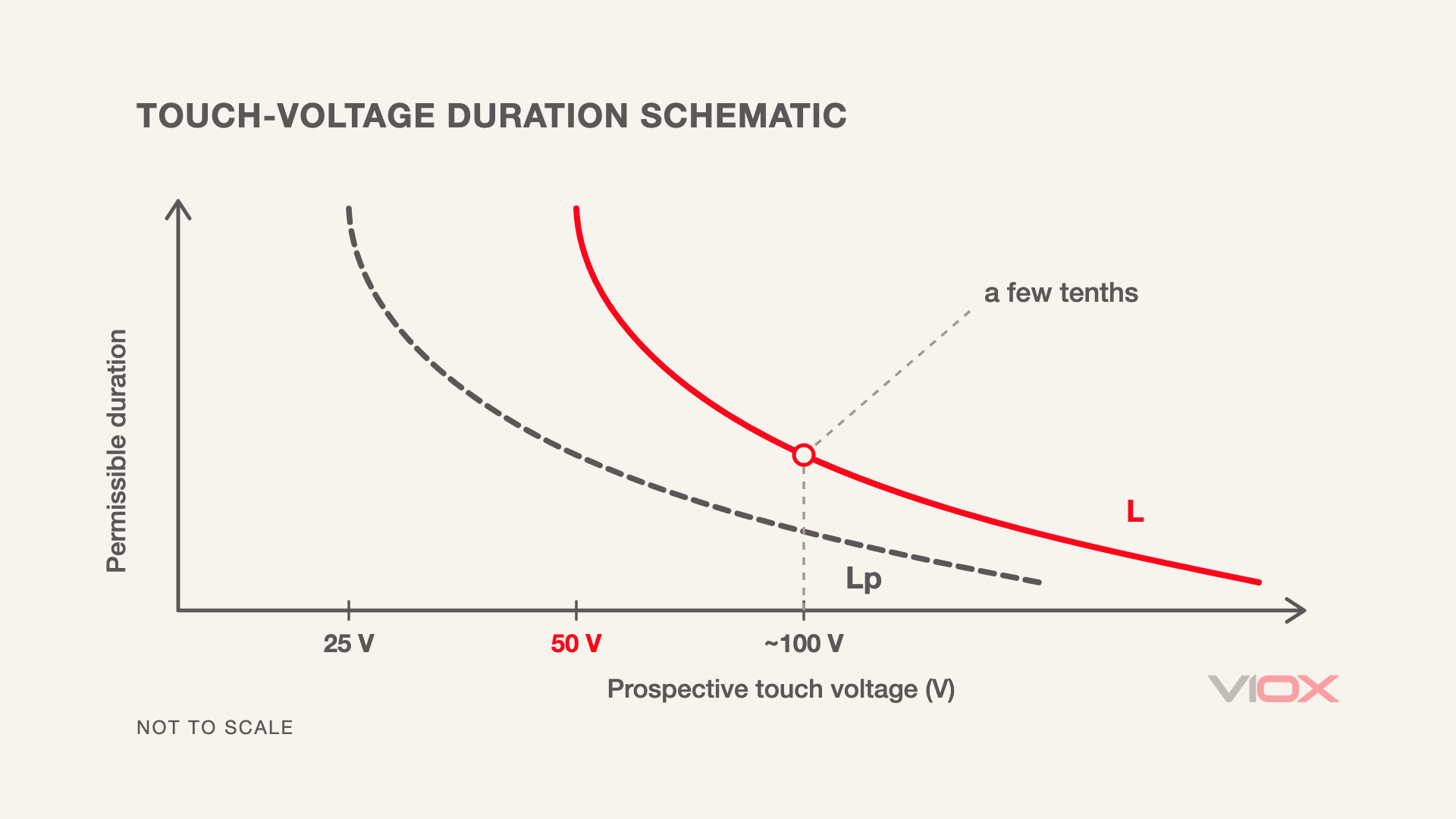
Two behaviors govern both curves. At or below UL — 50 V in dry conditions on Curve Lou 25 V in wet conditions on Curve Lp — permissible duration extends indefinitely, because body current stays below the fibrillation zone under those defined conditions. Once prospective touch voltage exceeds 50 V monté sur rail DIN (ou 25 V), permissible duration drops steeply: the higher the touch voltage, the shorter the tolerable shock duration. That steep slope explains why Table 41.1 tightens at every step from 120 V jusqu'à >400 V.
Why Hand-Held Equipment Gets the Strict End: Let-Go
Why assume sustained skin contact rather than an immediate reflex withdrawal? The answer is the physiological let-go mechanism.
When an operator grips a metal-enclosed hand-held tool or portable appliance, palm and fingers wrap around the housing. If an internal phase conductor faults to that casing, shock current flows through the hand and forearm muscles controlling finger flexion. Because flexor muscles overpower extensors under electrical stimulation, the current causes involuntary muscular contraction (tetanic grip). The user cannot open their hand to release the live casing; shock exposure is forced to continue until an upstream protective device interrupts the circuit. Stationary enclosures, by contrast, are ordinarily brushed or touched without a closed grip, leaving voluntary withdrawal physically possible.
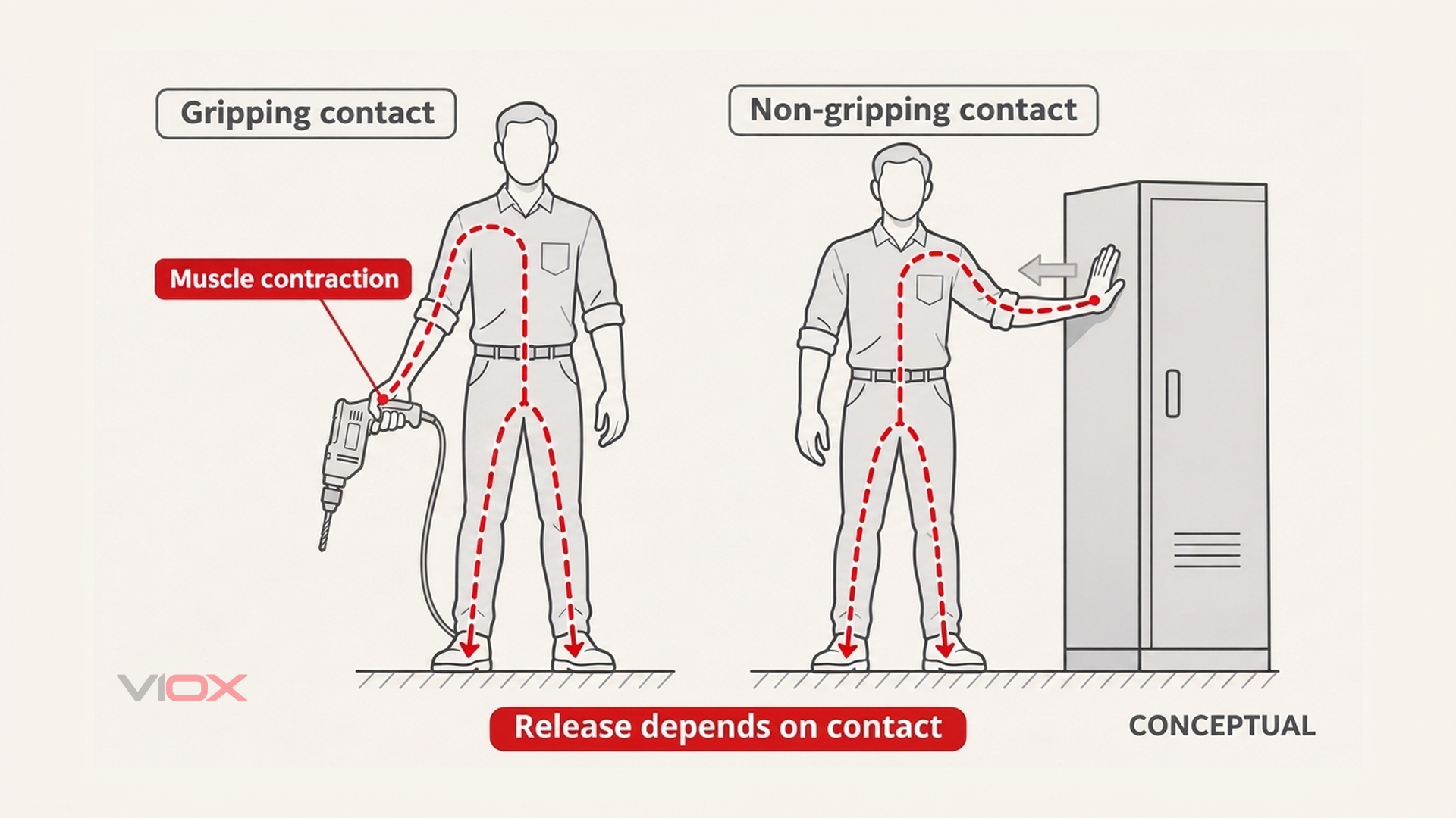
Because final circuits within the scope of Table 41.1 feed socket outlets and portable or hand-held equipment where involuntary grip must be assumed, IEC 60364-4-41 ties those circuits directly to the physiological curve. An illustrative, order-of-magnitude voltage-divider check connects 230 V à 0.4 s.
During a phase-to-enclosure earth fault in a TN circuit, nominal voltage U0 divides across the phase conductor impedance and the protective earthing (PE) conductor impedance. For phase and PE conductors of the same metal, impedance scales inversely with cross-sectional area (A_phase et A_PE). Defining m as their cross-section ratio gives the illustrative prospective touch voltage UT:
m = A_phase / A_PE
UT ≈ U0 × m / (1 + m)
Where phase and PE conductors share equal cross-sections (m = 1), UT is on the order of half of U0 — in a 230 V system, an illustrative band of roughly 90-115 V depending on supply-side impedance factors.
Plotting an order-of-magnitude touch voltage around 100 V onto Curve L in IEC TR 61200-413 yields a permissible duration of only a few tenths of a second. Table 41.1’s 0.4 s value at 230 V sits squarely in that window. Read properly as an order-of-magnitude check rather than an exact single-voltage identity, the chain is clear: equal-section final wiring leaves roughly half of U0 on the casing, muscular lock prevents let-go, and Curve L leaves only a few tenths of a second to disconnect.
Why Distribution Circuits Get 5 Seconds — and What 5 Seconds Does Not Mean
How, then, can TN distribution circuits (and circuits outside Table 41.1) allow 5 s (1 s in TT)? Crucially, 5 s is not read off the physiological shock curve. Instead, it is an installation-engineering synthesis of four factors specific to distribution feeders and fixed equipment:
- Lower fault and simultaneous-contact probability: Fixed switchboards, busbars, and stationary equipment experience far less mechanical wear and flexing than portable cords and tools, reducing both insulation-failure rates and the probability that someone is touching an enclosure at the exact instant a fault occurs.
- Ability to disengage: Stationary enclosures are not gripped in the palm, so a person making incidental contact can pull away voluntarily rather than being locked onto live metalwork.
- Selectivity across protection tiers: Distribution feeders supply downstream sub-boards and final circuits. Requiring sub-second tripping on every upstream feeder fault would destroy time-graded discrimination and black out healthy downstream circuits during local faults.
- Conductor thermal stability (
I²t) and reliable operation at lower fault currents: Long feeders add impedance that lowers earth-fault current, pushing breakers or fuses out of instantaneous clearing into slower inverse-time or short-time delayed zones. Allowing up to5 sleaves workable room for reliable device operation while keeping adiabatic energy let-through (I²t) withinPEconductor thermal limits.
Those four engineering trade-offs explain why 5 s exists — and reinforce what it never means: 5 s remains a ceiling for compliance verification, not a delay setting to aim for.
One system boundary completes the rule set: in an Régime de neutre IT, automatic disconnection is not required on the first earth fault because first-fault current is minimal and supervision relies on insulation monitoring, so Table 41.1’s first-fault limits do not apply.
How the Limit Is Actually Met
IEC 60364-4-41 states limits in seconds, whereas MCBs, MCCBs, fuses, and RCDs respond to actuel. Achieving disconnection on time depends on how the earthing system converts an insulation fault into fault current.
Dans un TN system, exposed metalwork returns to source neutral via metallic PE monté sur rail DIN (ou PEN) conductors. An earth fault forms a closed phase-to-PE loop whose fault current depends on U0 and fault-loop impedance (Zs). When Zs is low enough, fault current reaches or exceeds the threshold (Ia) that drives the overcurrent device to open within 0.4 s ou 5 s — making the time limit a joint requirement on fault current and device time-current characteristic (with an RCD used where Zs is too high).
Dans un TT system, fault current returns through earth-electrode resistances, keeping fault current too small to trip overcurrent breakers or fuses within 0.2 s (at 230 V) or 1 s. Compliance therefore normally depends on a residual current device (RCD).
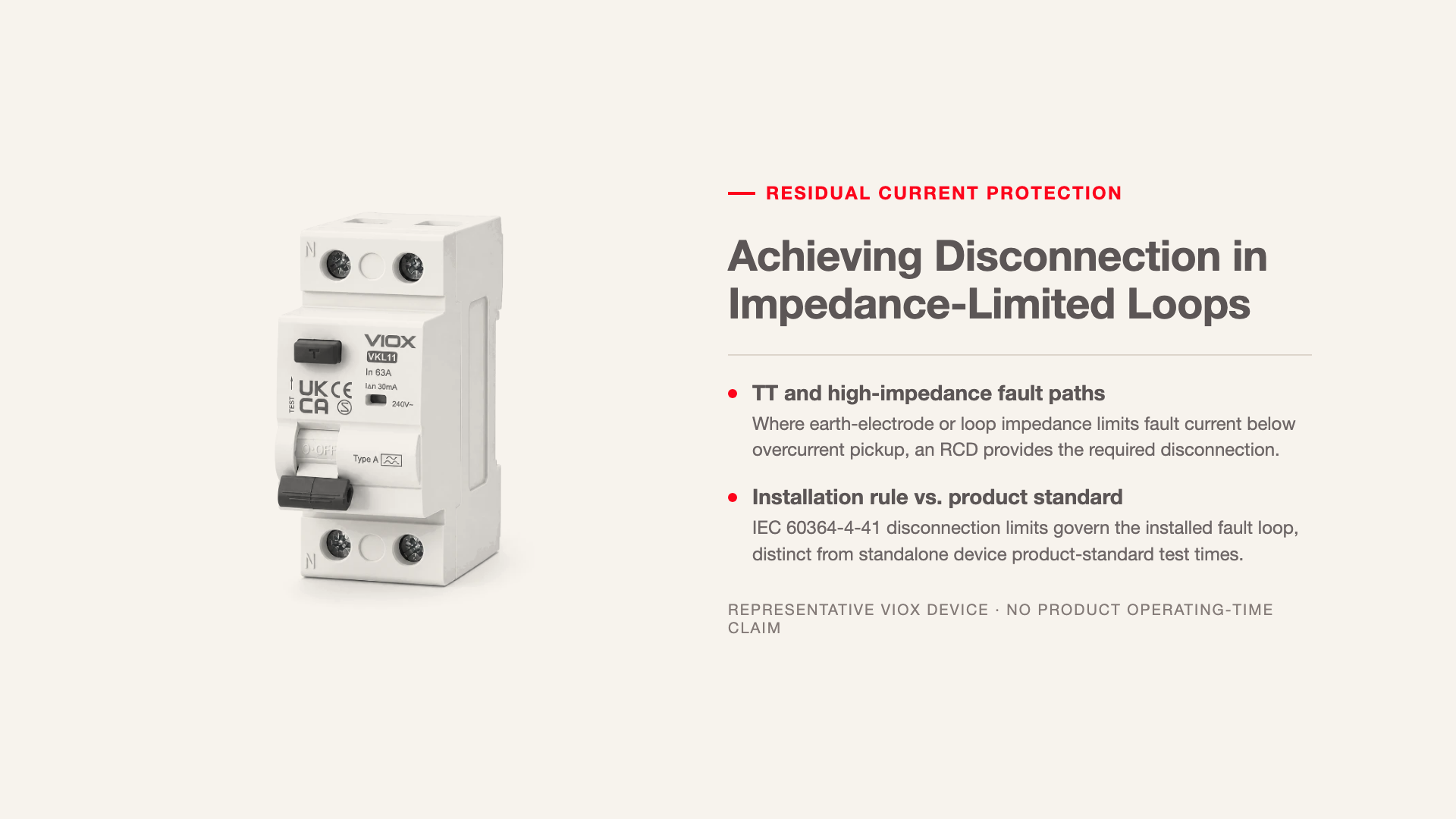
Observe one strict boundary when reading datasheets: installation disconnection times in IEC 60364-4-41 do not equal intrinsic operating times in protective-device product standards, which test standalone devices at standardized laboratory currents rather than complete installed fault loops; do not confuse the two. For rated residual current (IΔn) sizing, see our guide to RCCB sensitivity selection, and for wider protection architecture see our overview of protection contre les défauts à la terre.
Four Misreadings
Four recurring shortcuts distort how 0.4 s et 5 s get applied on panel schedules.
Misreading: “5 s means a fault can wait 5 seconds before tripping.” Wrong. The 5 s figure is an upper ceiling, not a target delay and not a guarantee that touching an energized enclosure for 5 s is safe at arbitrary touch voltages; circuits should always disconnect as fast as selective coordination permits.
Misreading: “0.4 s and 5 s are short-circuit protection times.” Wrong. Both limits govern fault protection (indirect-contact shock protection) under IEC 60364-4-41, addressing prospective touch voltage on exposed conductive parts — a separate requirement from phase-to-phase or phase-to-neutral short-circuit conductor protection.
Misreading: “Every TN feeder — and everything downstream — can use 5 s.” Wrong. The 5 s limit applies only to the distribution circuit itself (and qualifying circuits outside Table 41.1). Any downstream socket-outlet or final circuit within the scope of Table 41.1 must independently meet Table 41.1’s strict limit (0.4 s à 230 V in TN) and cannot be covered by an upstream feeder’s 5 s allowance.
Misreading: “5 s is also read off the physiological shock curve.” Wrong. Only Table 41.1’s sub-second values (0.4 s à 230 V TN) trace back to the physiological touch-voltage curves of IEC 60479-1 and IEC TR 61200-413; 5 s is an engineering synthesis of contact probability, voluntary release, selectivity, and I²t thermal withstand. Mixing their origins blurs where each limit applies.
Because maximum disconnection time limits are ultimately achieved through protective devices, engineers can explore VIOX’s disjoncteurs à boîtier moulé (MCCB) when reviewing low-voltage circuit protection hardware.
FAQ
Why is the disconnection time 0.4 s for a 230 V TN final circuit?
During an earth fault on a 230 V TN final circuit with equal phase and PE cross-sections (m = 1), illustrative prospective touch voltage is on the order of half of U0 (roughly 90-115 V, around 100 V). Gripping hand-held equipment prevents let-go, and Curve L in IEC TR 61200-413 permits only a few tenths of a second around 100 V — where Table 41.1 sets 0.4 s.
Does the 5 s limit mean a fault can safely persist for 5 seconds?
No. In IEC 60364-4-41, 5 s is strictly a maximum permissible ceiling for TN distribution circuits (and circuits outside Table 41.1), never a delay target or a promise that touching a faulted enclosure for 5 s is safe at elevated touch voltages. Faults should always be cleared as rapidly as selectivity allows.
Why are TT disconnection times shorter than TN?
In Table 41.1, TT limits (0.3 s, 0.2 s, 0.07 s, 0,04 s) are shorter than TN limits (0.8 s, 0.4 s, 0.2 s, 0,1 s), and TT distribution circuits allow 1 s par rapport à 5 s. Because TT fault loops return through earth-electrode resistance rather than a metallic PE return to source neutral, prospective touch voltage takes a larger share of U0, demanding faster disconnection typically provided by an RCD.
Is 0.4 s the operating time of the circuit breaker itself?
No. The 0.4 s limit in IEC 60364-4-41 is an installation rule for the complete circuit at its actual earth-fault current. Protective-device product standards define separate intrinsic break-time test values at standardized laboratory currents; the two sets of times must not be confused.
What happens on the first earth fault in an IT system?
In an IT system, live conductors are isolated from earth or earthed through high impedance, keeping first earth-fault current minimal so hazardous touch voltages do not arise. Automatic disconnection is not required on the first fault; instead, insulation monitoring alerts operators to locate and clear the fault.
Sources
- IEC 60364-4-41: Low-voltage electrical installations — Protection for safety — Protection against electric shock (automatic disconnection of supply framework, Table 41.1 final-circuit maximum disconnection times, and
5 s/1 sdistribution-circuit limits). - IEC 60479-1: Effects of current on human beings and livestock — General aspects (physiological time-current effect zones, ventricular-fibrillation risk, and muscular let-go thresholds).
- IEC TR 61200-413: Electrical installation guide — Explanatory notes to measures of protection against indirect contact by automatic disconnection of supply (prospective touch-voltage duration curves
LetLp, and conventional50 Vet25 Vtouch-voltage limits).