

Que signifie kVA sur la plaque signalétique d'un transformateur ?
kVA (kilovolt-ampère) représente la puissance apparente d'un transformateur, indiquant la tension et le courant maximum que l'unité peut supporter simultanément sans surchauffe. Contrairement au kW (kilowatt) qui mesure uniquement la puissance active, le kVA tient compte à la fois de la puissance active (kW) et de la puissance réactive (kVAR), ce qui le rend indépendant du facteur de puissance de la charge. Cette valeur nominale garantit que le transformateur peut alimenter tout type de charge (résistive, inductive ou capacitive) sans que le fabricant ait connaissance de l'application spécifique.
Principaux enseignements
- Le kVA mesure la puissance apparente (tension × courant), tandis que le kW mesure uniquement la puissance active qui effectue un travail réel
- Les transformateurs sont dimensionnés en kVA, pas en kW, car les fabricants ne peuvent pas prédire le facteur de puissance des charges futures
- Pertes cuivre dépendent du courant (I²R), pertes fer dépendent de la tension - les deux déterminent les limites thermiques exprimées en VA
- Calcul du kVA monophasé: kVA = (Tension × Courant) / 1000
- Calcul du kVA triphasé: kVA = (Tension × Courant × 1,732) / 1000
- Efficacité maximale se produit généralement à 70-80% de la charge kVA nominale
- Toujours dimensionner les transformateurs avec une marge de sécurité de 20 à 25% au-dessus de la charge calculée pour éviter la surcharge et permettre une expansion future
Le triangle de puissance : comprendre kW, kVAR et kVA
Pour comprendre pourquoi les transformateurs utilisent les valeurs nominales en kVA, il faut d'abord comprendre la relation entre les différents types de puissance dans les systèmes électriques à courant alternatif. La puissance électrique dans les circuits à courant alternatif se compose de trois composantes formant ce que les ingénieurs appellent le “ triangle de puissance ”.”
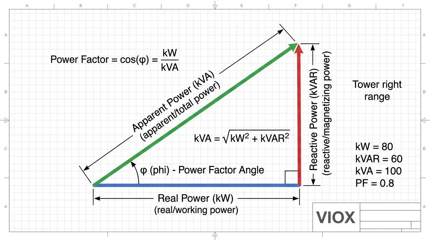
Puissance active (kW) représente la puissance de travail réelle qui effectue un travail utile : faire fonctionner des moteurs, des éléments chauffants ou des circuits d'éclairage. C'est la puissance que les services publics facturent et qui effectue un travail mesurable dans le système.
Puissance réactive (kVAR) maintient les champs électromagnétiques requis par les charges inductives comme les moteurs et les transformateurs, ou les charges capacitives comme les batteries de condensateurs. Bien que la puissance réactive n'effectue pas de travail utile, elle est essentielle au fonctionnement de ces appareils et circule entre la source et la charge.
Puissance apparente (kVA) est la somme vectorielle de la puissance active et de la puissance réactive, représentant la puissance totale que la source doit fournir au circuit. Mathématiquement, cette relation est exprimée comme suit :
kVA = √(kW² + kVAR²)
Les facteur de puissance (PF) est le rapport de la puissance active à la puissance apparente :
PF = kW / kVA
Un facteur de puissance de 1,0 (unité) indique que toute la puissance est de la puissance active sans composante réactive. Les charges industrielles typiques fonctionnent avec des facteurs de puissance compris entre 0,7 et 0,95, ce qui signifie que la puissance apparente (kVA) est toujours égale ou supérieure à la puissance active (kW).
Pourquoi la puissance nominale du transformateur est-elle exprimée en kVA plutôt qu'en kW ?
La question fondamentale que se posent de nombreux ingénieurs et techniciens est de savoir pourquoi les fabricants de transformateurs utilisent universellement le kVA plutôt que le kW pour leurs valeurs nominales. Cette pratique n'est pas arbitraire : elle est enracinée dans la nécessité technique et les contraintes d'ingénierie pratiques.
Raison 1 : Facteur de puissance de charge inconnu
Lorsqu'un fabricant de transformateurs conçoit et construit une unité, il n'a aucune connaissance du type de charge qui y sera connectée sur le terrain. Le transformateur pourrait alimenter :
- Resistive loads (radiateurs, éclairage incandescent) avec PF ≈ 1,0
- Inductive loads (moteurs, contacteurs, transformateurs) avec PF = 0,6-0,9 en retard
- Charges mixtes avec des facteurs de puissance variables tout au long de la journée
- Charges capacitives (batteries de condensateurs, certains équipements électroniques) avec PF en avance
Étant donné que le même transformateur doit prendre en charge tous ces types de charges, l'indiquer en kW n'aurait aucun sens. Un transformateur d'une puissance nominale de 100 kW avec une charge résistive (PF = 1,0) ne pourrait fournir que 60 kW à une charge inductive avec PF = 0,6 sans dépasser ses limites thermiques. En indiquant la puissance en kVA, le fabricant fournit une mesure de capacité universelle indépendante des caractéristiques de la charge.
Raison 2 : Les pertes dépendent de la tension et du courant, pas du facteur de puissance
Les pertes du transformateur déterminent les limites thermiques et donc la puissance nominale. Ces pertes se composent de deux composantes principales :
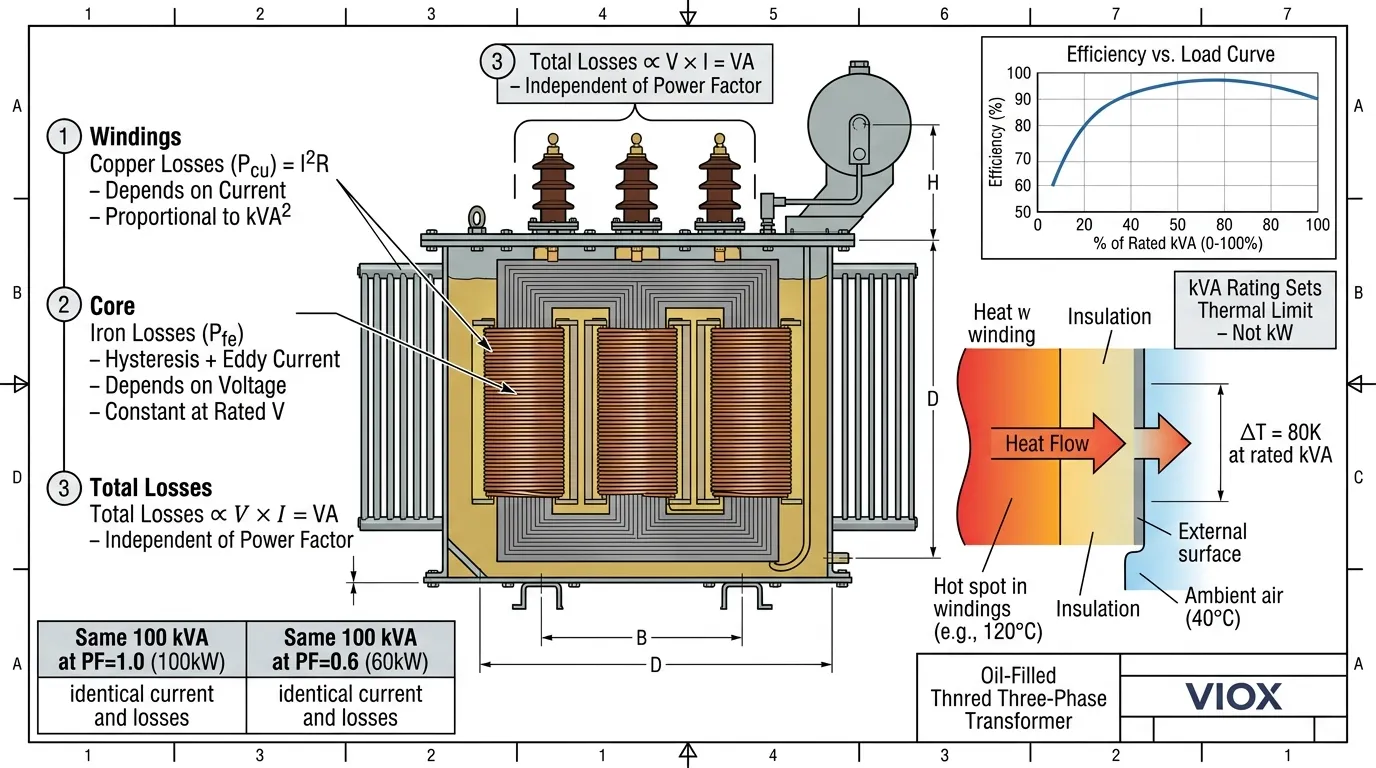
Pertes cuivre (pertes I²R) : Elles se produisent dans les enroulements du transformateur en raison de la résistance des conducteurs en cuivre. Les pertes cuivre sont proportionnelles au carré du courant circulant dans les enroulements :
Pcu = I² × R
Étant donné que le courant (I) est directement lié à la puissance apparente (kVA), les pertes cuivre dépendent entièrement de la charge en kVA, et non du facteur de puissance.
Pertes fer (pertes dans le noyau) : Elles se composent des pertes par hystérésis et par courants de Foucault dans le noyau du transformateur. Les pertes fer dépendent de la tension appliquée au transformateur et de la fréquence :
Pfe ∝ V² × f
Les pertes fer sont essentiellement constantes chaque fois que le transformateur est alimenté, quelle que soit la charge.
Pertes totales : Étant donné que les pertes cuivre dépendent du courant et que les pertes fer dépendent de la tension, les pertes totales dans un transformateur sont proportionnelles à :
Pertes totales ∝ V × I = VA (volt-ampères)
Les pertes sont totalement indépendantes du facteur de puissance de la charge. Qu'il s'agisse d'alimenter une charge purement résistive (PF = 1,0) ou une charge fortement inductive (PF = 0,5), la chaleur générée à l'intérieur du transformateur dépend uniquement de la tension et du courant, exprimés en VA ou kVA.
Raison 3 : L'élévation de température est corrélée à la puissance apparente
L'élévation de température d'un transformateur détermine la durée de vie de son isolation et ses limites de fonctionnement sûres. L'isolation du transformateur (généralement de classe A (105 °C), classe B (130 °C), classe F (155 °C) ou classe H (180 °C)) se dégrade avec la température, suivant l'équation d'Arrhenius où la durée de vie de l'isolation diminue de moitié pour chaque augmentation de 10 °C au-dessus de la température nominale.
Étant donné que les pertes du transformateur (et donc la génération de chaleur) dépendent de la puissance apparente (kVA), l'élévation de température est également corrélée au kVA, et non au kW. Un transformateur fournissant 100 kVA à PF = 1,0 (100 kW) génère la même chaleur que le même transformateur fournissant 100 kVA à PF = 0,6 (60 kW). Dans les deux cas, le courant est identique, produisant des pertes cuivre identiques.
Comment calculer la puissance nominale en kVA d'un transformateur
Un dimensionnement approprié des transformateurs est essentiel pour la conception des systèmes électriques. Un sous-dimensionnement entraîne une surchauffe, une réduction de la durée de vie et une défaillance potentielle. Un surdimensionnement entraîne des coûts inutiles, un encombrement plus important et une efficacité potentiellement plus faible à faible charge.
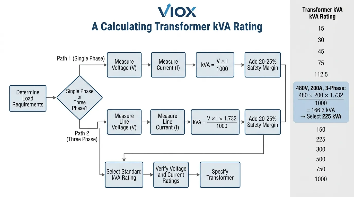
Calcul de la puissance nominale kVA d'un transformateur monophasé
Pour les transformateurs monophasés, la puissance nominale kVA est calculée à l'aide de la relation simple entre la tension et le courant :
kVA = (V × I) / 1000
Où ?
- V = Tension (volts)
- I = Courant (ampères)
- 1000 = Facteur de conversion en kilovoltampères
Exemple De Calcul:
Un transformateur monophasé fournissant 240 V à 125 A :
kVA = (240 × 125) / 1000 = 30 kVA
Les puissances nominales standard des transformateurs monophasés suivent généralement la série de nombres préférés R10 : 5, 10, 15, 25, 37,5, 50, 75, 100, 167, 250, 333, 500 kVA. Toujours arrondir à la taille standard supérieure.
Calcul de la puissance nominale kVA d'un transformateur triphasé
Les transformateurs triphasés nécessitent de tenir compte de la relation de phase entre les trois conducteurs. Le calcul inclut la racine carrée de 3 (1,732) :
kVA = (V × I × 1,732) / 1000
Où ?
- V = Tension entre phases (volts)
- I = Courant de ligne (ampères)
- 1,732 = √3 (racine carrée de 3)
Exemple De Calcul:
Un transformateur triphasé fournissant 480 V à 150 A :
kVA = (480 × 150 × 1,732) / 1000 = 124,7 kVA
Arrondir à la taille standard : 150 kVA.
Les puissances nominales standard des transformateurs triphasés incluent : 15, 30, 45, 75, 112,5, 150, 225, 300, 500, 750, 1000, 1500, 2000, 2500, 3000, 3750, 5000 kVA.
Conversion kVA en ampères
Lorsque la puissance nominale kVA est connue et que vous devez déterminer la capacité de courant maximale :
Monophasé :
I = (kVA × 1000) / V
Triphasé :
I = (kVA × 1000) / (V × 1,732)
Exemple : I_nominal = 500 000 / (√3 × 480) = 601 A
I = (500 × 1000) / (480 × 1,732) = 601,4 A
Directives et meilleures pratiques pour le dimensionnement des transformateurs
Inclure une marge de sécurité
La meilleure pratique d'ingénierie recommande de dimensionner les transformateurs avec une marge de sécurité de 20 à 25 % au-dessus de la charge maximale calculée. Cela tient compte de :
- La croissance de la charge et l'expansion future
- Les surcharges temporaires pendant le démarrage du moteur
- Les variations des courants de charge réels par rapport aux courants de charge estimés
- Les exigences de régulation de tension sous charge
Calcul avec marge de sécurité :
kVA requis = kVA de charge calculée / 0,8
Par exemple, si la charge calculée est de 200 kVA :
kVA requis = 200 / 0,8 = 250 kVA
Tenir compte des caractéristiques de la charge
Différents types de charge nécessitent différentes approches de dimensionnement :
| Le Type De Charge | Caractéristiques | Considération de dimensionnement |
|---|---|---|
| Éclairage | Stable, résistif | Basé sur la charge réelle avec une marge de 20 % |
| Moteurs CVC | Courant de démarrage élevé | Dimensionner pour le courant d'appel ou utiliser un démarrage à tension réduite |
| Soudeuses | Intermittent, courant élevé | Utiliser les facteurs de diversité selon NEC 630 |
| Entraînements à vitesse variable | Non linéaire, contenu harmonique | Surdimensionner de 20 % ou utiliser des transformateurs à facteur K |
| Les Centres De Données | Haute densité, refroidissement critique | Prévoir la redondance (N+1 ou 2N) |
| Recharge de véhicules électriques | Charges pulsées, incertitude de croissance | Dimensionner pour l'expansion future, envisager une conception modulaire |
Considérations relatives à l'efficacité
L'efficacité du transformateur varie avec la charge. L'efficacité maximale se produit généralement à 50-60 % de la charge nominale pour les transformateurs de type sec et 70-80 % pour les unités remplies d'huile. Un fonctionnement constant à des charges très faibles (inférieures à 30 %) entraîne une faible efficacité en raison des pertes fixes dans le noyau.
L'efficacité peut être calculée comme suit :
Efficacité = (Puissance de sortie / Puissance d'entrée) × 100 = (kWsur / (kWsur + Pertes)) × 100
Les rendements typiques des transformateurs modernes varient de 97 % à 99 % à la charge nominale, avec des transformateurs à rendement supérieur dépassant 99 % d'efficacité.
kVA vs kW : Tableau de comparaison pratique
Le tableau suivant illustre la relation entre kVA, kW et facteur de puissance pour des applications industrielles typiques :
| Puissance du transformateur (kVA) | Facteur de puissance (PF) | Puissance active (kW) | Puissance réactive (kVAR) | Application Example |
|---|---|---|---|---|
| 100 kVA | 1,0 (unité) | 100 kW | 0 kVAR | Chauffage électrique, charges résistives |
| 100 kVA | 0.9 | 90 kW | 43,6 kVAR | Charges industrielles mixtes |
| 100 kVA | 0.8 | 80 kW | 60 kVAR | Charges de moteur, typique industriel |
| 100 kVA | 0.7 | 70 kW | 71,4 kVAR | Industriel lourd, beaucoup de moteurs |
| 100 kVA | 0.6 | 60 kW | 80 kVAR | Mauvais facteur de puissance, non corrigé |
Aperçu clé : Notez que, quel que soit le facteur de puissance, le courant du transformateur et la charge thermique restent identiques pour la même puissance en kVA. Un transformateur de 100 kVA fonctionne à pleine capacité, qu'il fournisse 100 kW à PF unitaire ou 60 kW à 0,6 PF. Cela démontre pourquoi le kVA est la métrique d'évaluation appropriée.
Interprétation des données de la plaque signalétique du transformateur
La compréhension des plaques signalétiques des transformateurs est essentielle pour une application correcte. Les données standard de la plaque signalétique comprennent :
- Caractéristiques primaires : Puissance en kVA (capacité de puissance apparente), Tension(s) primaire(s) (tension d'entrée nominale), Courant primaire (courant à pleine charge), Fréquence (généralement 50 Hz ou 60 Hz)
- Caractéristiques secondaires : Tension secondaire (tension de sortie à la charge nominale), Courant secondaire (courant de sortie à pleine charge), Tensions de prise (si équipé d'un changeur de prises)
- Données de performance : Tension d'impédance (%Z, généralement 4-6 % pour les transformateurs de distribution), Élévation de température (par exemple, 80 °C, 115 °C, 150 °C), Classe d'isolation (A, B, F, H), Rendement à différents niveaux de charge, Niveau sonore (décibels)
- Données physiques : Poids (noyau, bobine, total), Dimensions, Schéma de connexion (pour les unités triphasées), Méthode de refroidissement (AN, AF, ONAN, ONAF)
La puissance en kVA sur la plaque signalétique représente la charge continue que le transformateur peut supporter à la tension et à la fréquence nominales sans dépasser les limites d'élévation de température dans la température ambiante spécifiée (généralement 30 °C en moyenne, 40 °C maximum).
Puissances en kVA courantes des transformateurs et applications
Les transformateurs sont fabriqués dans des puissances en kVA normalisées pour permettre l'interchangeabilité et les économies d'échelle. Les puissances courantes et les applications typiques comprennent :
- Distribution basse tension (jusqu'à 600 V) :
- 5-15 kVA: Petits commerces, résidentiel, circuits de commande
- 25-75 kVA: Bâtiments commerciaux, petite industrie
- 112,5-300 kVA: Usines industrielles, centres commerciaux
- 500-1000 kVA: Grande industrie, hôpitaux, centres de données
- 1500-2500 kVA: Grandes installations industrielles, sous-stations
- Moyenne tension (jusqu'à 35 kV) :
- 1000-5000 kVA: Distribution primaire, grandes installations
- 7500-15000 kVA: Sous-stations de services publics, parcs industriels
Lignes directrices de sélection :
- Faites correspondre le kVA du transformateur à la charge connectée plus une marge de sécurité
- Tenez compte des projections de croissance de la charge pour les 10 à 15 prochaines années
- Évaluez les exigences d'efficacité énergétique (normes DOE 2016 aux États-Unis)
- Évaluez le contenu harmonique et spécifiez Transformateurs à facteur K si nécessaire
- Coordonner avec protection des circuits notes
Courte section FAQ
Q : Quelle est la différence entre kVA et kW dans les puissances des transformateurs ?
R : kVA (kilovolt-ampère) représente la puissance apparente, c'est-à-dire la puissance totale que le transformateur peut fournir, y compris la puissance réelle (kW) et la puissance réactive (kVAR). kW (kilowatt) représente uniquement la puissance réelle qui effectue un travail utile. La relation est la suivante : kW = kVA × Facteur de puissance. Les transformateurs sont évalués en kVA car ils doivent gérer à la fois le courant réel et le courant réactif, et le fabricant ne peut pas prédire quelles charges de facteur de puissance seront connectées.
Q : Comment convertir kW en kVA pour le dimensionnement du transformateur ?
R : Pour convertir kW en kVA, divisez le kW par le facteur de puissance : kVA = kW / PF. Par exemple, si votre charge est de 400 kW avec un facteur de puissance de 0,8, vous avez besoin d'un transformateur d'au moins 500 kVA (400 ÷ 0,8). Ajoutez toujours une marge de sécurité de 20 % : 500 kVA ÷ 0,8 = taille minimale du transformateur de 625 kVA, arrondissez à la valeur standard de 750 kVA.
Q: Puis-je utiliser un transformateur dont la puissance nominale en kVA est supérieure à celle requise par ma charge ?
R: Oui, vous pouvez utiliser un transformateur surdimensionné. Cependant, un fonctionnement nettement en dessous de la capacité nominale (charge constamment inférieure à 30 %) réduit l'efficacité en raison des pertes fixes dans le noyau. L'efficacité maximale se produit généralement entre 50 et 80 % de la puissance nominale en kVA. Un surdimensionnement de 20 à 25 % au-dessus de la charge calculée est recommandé pour les marges de sécurité et la croissance future, mais un surdimensionnement de 100 % ou plus gaspille de l'énergie et du capital.
Q: Que se passe-t-il si je surcharge un transformateur au-delà de sa puissance nominale en kVA ?
R: La surcharge d'un transformateur provoque un échauffement excessif, ce qui accélère le vieillissement de l'isolation et réduit sa durée de vie. Selon l'équation d'Arrhenius, la durée de vie de l'isolation diminue environ de moitié pour chaque augmentation de température de 10 °C au-dessus des limites nominales. Une surcharge continue peut entraîner une défaillance de l'isolation, des courts-circuits, un incendie du transformateur ou une défaillance catastrophique. Ne jamais dépasser la puissance nominale en kVA indiquée sur la plaque signalétique, sauf en cas de brèves surcharges d'urgence spécifiées par le fabricant.
Q: Comment le facteur de puissance affecte-t-il le dimensionnement du transformateur ?
R: Le facteur de puissance affecte directement la relation entre kW et kVA. À un facteur de puissance unitaire (1,0), les kW sont égaux aux kVA. À des facteurs de puissance inférieurs (charges industrielles typiques : 0,7-0,9), les kVA requis sont supérieurs aux kW. Par exemple, une charge de 100 kW à 0,8 PF nécessite une capacité de transformateur de 125 kVA. Un mauvais facteur de puissance signifie que vous avez besoin d'un transformateur plus grand (plus cher) pour fournir la même puissance réelle, c'est pourquoi correction du facteur de puissance est économiquement avantageux.
Q: Quelle est la formule pour calculer les kVA d'un transformateur triphasé ?
R: Pour les transformateurs triphasés : kVA = (Tension × Courant × 1,732) / 1000, où la tension est la tension entre phases, le courant est le courant de ligne et 1,732 est la racine carrée de 3 (√3). Par exemple, un transformateur alimentant du triphasé 480 V à 200 A serait : (480 × 200 × 1,732) / 1000 = 166,3 kVA — arrondir à la taille standard de 225 kVA.
Q: Les pertes du transformateur sont-elles les mêmes à différents facteurs de puissance avec la même charge en kVA ?
R: Oui. Les pertes cuivre du transformateur dépendent du carré du courant (I²R), et comme le courant est déterminé par les kVA (pas les kW), les pertes cuivre sont identiques pour la même charge en kVA quel que soit le facteur de puissance. Les pertes fer dépendent de la tension et sont constantes pour une tension donnée. Par conséquent, les pertes totales du transformateur — et par conséquent l'élévation de température — sont indépendantes du facteur de puissance lorsque la charge en kVA est constante. C'est la raison fondamentale pour laquelle les transformateurs sont évalués en kVA.
Conclusion
La compréhension des puissances nominales en kVA des transformateurs est fondamentale pour une conception appropriée du système électrique. Contrairement aux moteurs et autres charges qui sont évalués en kW parce que leur facteur de puissance est connu et relativement constant, les transformateurs doivent s'adapter à tout type de charge avec des facteurs de puissance variables. La puissance nominale en kVA fournit une métrique universelle qui garantit un fonctionnement sûr et fiable, que le transformateur alimente des radiateurs résistifs (PF ≈ 1,0), des moteurs industriels (PF ≈ 0,8) ou des charges fortement inductives (PF < 0,7).
La base technique des puissances nominales en kVA réside dans les mécanismes de perte du transformateur : les pertes cuivre dépendent du courant, les pertes fer dépendent de la tension, et la combinaison dépend des voltampères (VA) — pas des watts. Étant donné que l'élévation de température du transformateur détermine la durée de vie de l'isolation et le fonctionnement sûr, et que l'élévation de température est corrélée à la puissance apparente (kVA) plutôt qu'à la puissance réelle (kW), la puissance nominale en kVA est la seule spécification techniquement valable.
Pour les ingénieurs, les entrepreneurs et les gestionnaires d'installations, le calcul et la spécification corrects des puissances nominales en kVA des transformateurs sont essentiels. Un sous-dimensionnement entraîne une défaillance prématurée, des risques pour la sécurité et des perturbations opérationnelles. Un surdimensionnement gaspille du capital et de l'énergie. L'application des formules et des directives présentées dans cet article — ainsi que la marge de sécurité recommandée de 20 à 25 % — garantit une sélection optimale du transformateur pour toute application.
En tant que fabricant B2B d'équipements électriques, VIOX Electric fournit une assistance complète pour la spécification des transformateurs, la coordination de la protection, et la conception du système. La compréhension des puissances nominales en kVA permet de prendre des décisions d'achat éclairées et garantit une distribution d'énergie fiable pour les projets industriels, commerciaux et d'infrastructure dans le monde entier.
Note technique : Tous les calculs de kVA et les informations techniques de ce guide sont conformes aux normes IEEE C57.12.00, IEC 60076 et NEMA ST-20 pour les transformateurs de puissance. Pour des applications spécifiques, consultez toujours la dernière édition des normes applicables et la documentation du fabricant. VIOX Electric fournit un support technique pour la spécification des transformateurs et la conception des systèmes d'alimentation afin de garantir une sélection optimale des équipements et un fonctionnement fiable.
