
Why DC Fast Charger Protection Goes Beyond Basic Circuit Breakers
When a $50,000 electric vehicle connects to your charging station, you’re responsible for more than just delivering power—you’re protecting a significant investment against electrical threats that can strike in microseconds. In the EV charging infrastructure industry, inadequate protection isn’t just a technical oversight; it’s a liability that can result in equipment failure, vehicle damage, and costly downtime.
DC fast chargers face unique electrical challenges that standard protection devices cannot address. Unlike residential circuits, these systems handle high-power DC conversion (50kW to 350kW+), making them vulnerable to two critical failure modes: catastrophic overcurrent events that destroy power semiconductors, and transient overvoltages from lightning strikes or grid disturbances. This article examines the specialized protection requirements mandated by international standards and explains why proper SPD and fuse selection is non-negotiable for commercial EV charging operations.
Understanding the Dual Threat: Overcurrent vs. Overvoltage
Overcurrent Protection: Safeguarding Power Semiconductors
In DC fast chargers, overcurrent protection serves a more sophisticated purpose than preventing wire fires. The heart of every DC charging station is a power conversion module containing IGBTs (Insulated Gate Bipolar Transistors) or SiC MOSFETs—semiconductor devices that convert AC grid power to regulated DC output. These components are extraordinarily vulnerable to fault currents, with thermal failure occurring in milliseconds.
Standard circuit breakers respond too slowly for semiconductor protection. When an internal short circuit or “shoot-through” fault occurs, fault currents can reach 10-50 times the rated current within microseconds. By the time a conventional breaker trips (typically 20-100ms), the IGBT is already destroyed. This is where ultra-rapid semiconductor fuses become essential.
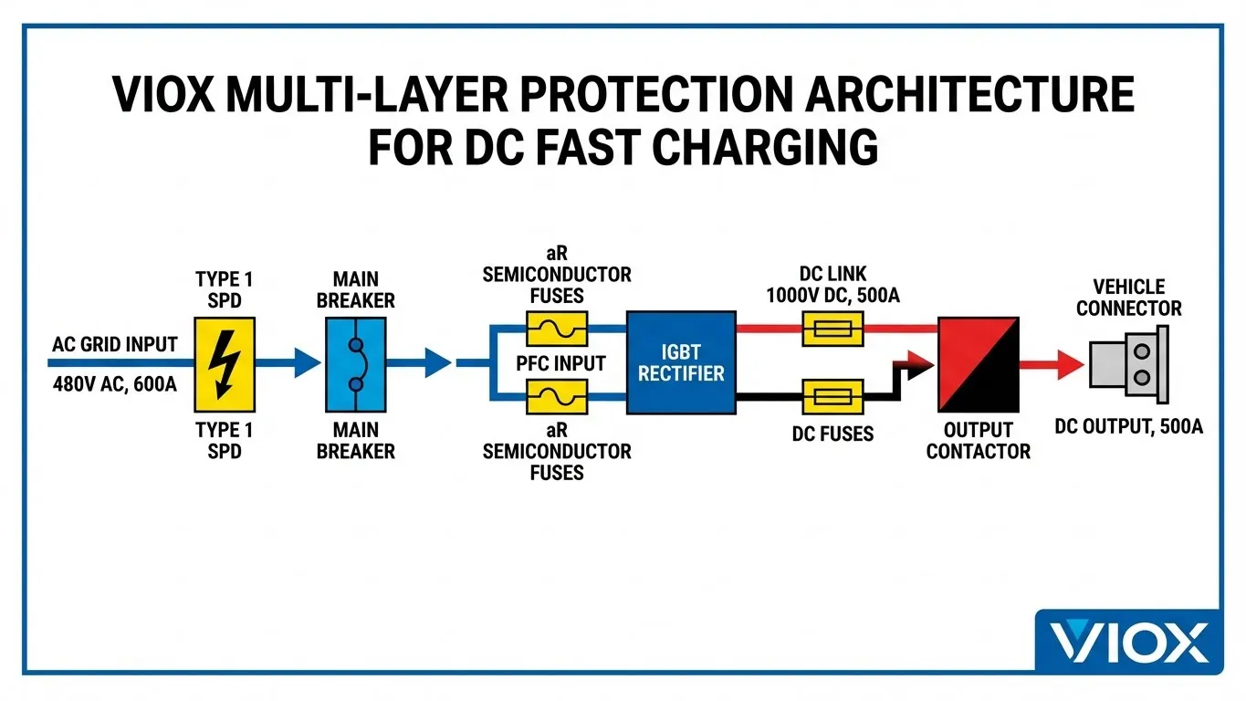
Key Protection Zones in DC Fast Chargers:
| Protection Zone | Device Type | Response Time | Primary Function |
|---|---|---|---|
| AC Input (Grid Side) | HBC Fuse or MCCB | 10-50ms | Prevent grid disturbance, building protection |
| AC-DC Rectifier | aR Semiconductor Fuse | <5ms | IGBT/diode bridge protection |
| DC Bus/Link | Ultra-Rapid DC Fuse | <3ms | Capacitor bank and inverter protection |
| DC Output (Vehicle Side) | DC-rated Fuse + Contactor | <10ms | Cable and vehicle BMS protection |
Overvoltage Protection: The Outdoor Installation Challenge
DC fast chargers are typically installed in exposed outdoor locations—highway rest stops, parking structures, and commercial lots—where they face constant exposure to transient overvoltages. Unlike controlled indoor environments, outdoor charging infrastructure experiences multiple surge sources:
- Lightning-induced surges: Even indirect strikes up to 1km away can induce voltage spikes exceeding 6,000V on power lines and communication cables.
- Switching transients: Utility grid switching operations, large motor startups, and capacitor bank switching create voltage spikes ranging from 800V to 2,000V.
- Electrostatic discharge: In dry climates, static buildup on insulated equipment can discharge into control circuits, damaging communication modules and display systems.
While electric vehicle Battery Management Systems (BMS) incorporate some overvoltage protection, they’re designed to protect the battery pack—not to absorb the full energy of a lightning surge. The charging station must provide primary surge protection before voltages reach the vehicle connector.
International Standards: Non-Negotiable Protection Requirements
IEC 61851 and UL 2202: The Regulatory Framework
The global EV charging industry operates under strict safety standards that explicitly mandate protection devices. IEC 61851 (Electric Vehicle Conductive Charging System) establishes fundamental requirements for all EV charging equipment, including specific provisions for overcurrent protection, ground fault detection, and surge immunity.
For North American markets, UL 2202 (Electric Vehicle Charging System Equipment) provides additional requirements aligned with National Electrical Code (NEC) Article 625. These standards mandate:
- Dedicated overcurrent protection devices sized according to charging equipment rating
- Ground fault protection meeting UL 2231 requirements for personnel safety
- Surge protection for outdoor installations (per NEC 2020 update)
- Arc fault detection and interruption capabilities
- Coordinated protection to isolate faults without total system shutdown
Compliance isn’t optional—these certifications are prerequisites for utility interconnection approvals, installation permits, and insurance coverage. Non-compliant installations face liability exposure and may be excluded from charging network participation agreements.
Selecting the Right SPD for EV Charging Applications
Type Classification and Coordination
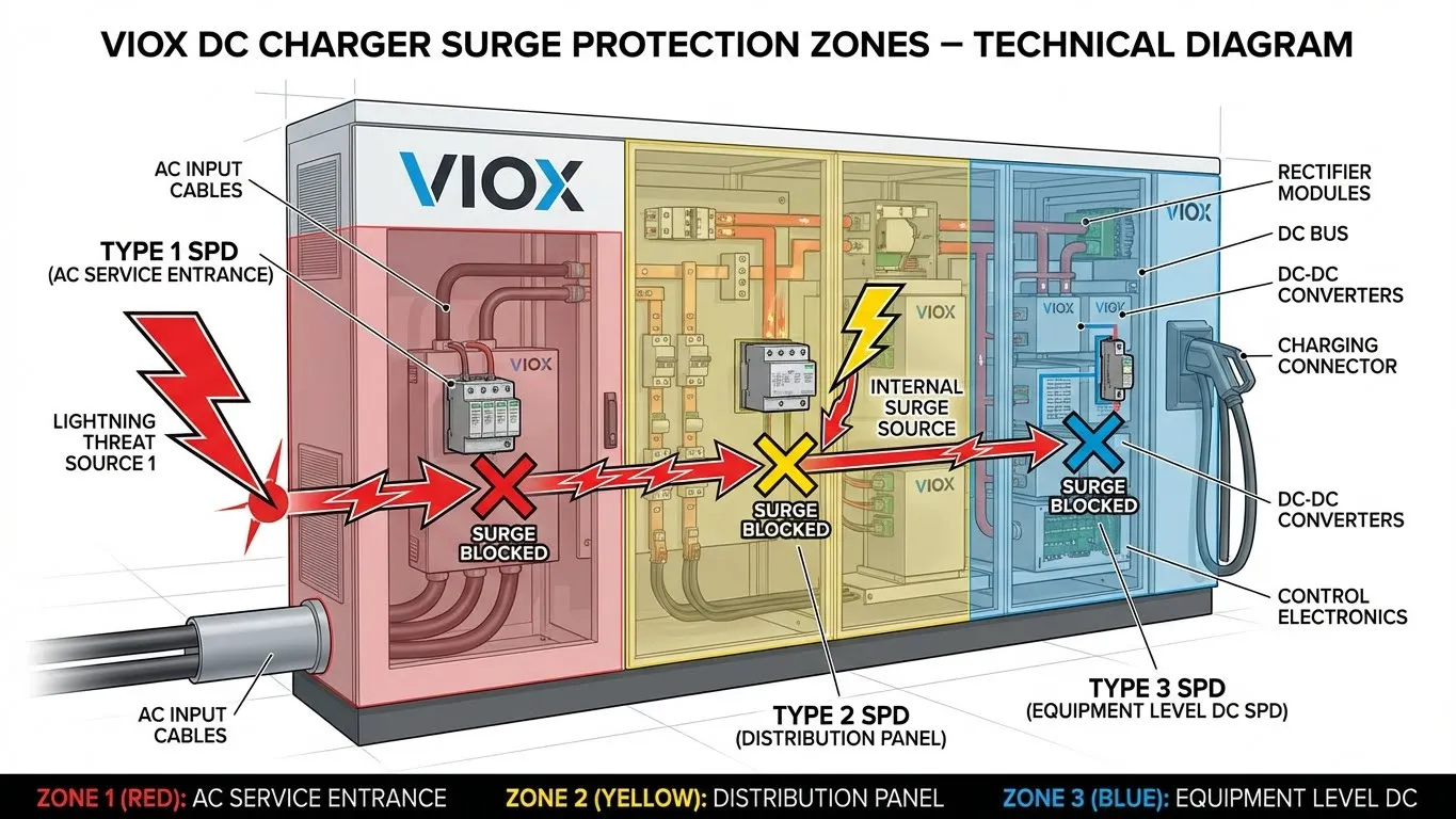
Surge Protection Devices for EV charging follow IEC 61643-11 classification, with selection based on installation location and threat level:
Type 1 SPD (Class I): Installed at the service entrance, these devices handle direct lightning strikes and utility-level surges. They’re designed for discharge currents up to 25kA per phase (10/350μs waveform) and are mandatory for charging stations with overhead power feeds or integrated lightning protection systems.
Type 2 SPD (Class II): Installed at distribution panels or directly at charging equipment. These provide protection against induced surges and switching transients, with discharge capacity of 20-40kA (8/20μs waveform). They’re the minimum requirement for all commercial EV charging installations.
Type 1+2 Combined SPD: Emerging as the preferred solution for DC fast chargers, these hybrid devices provide both lightning-level protection and induced surge protection in a single compact unit, simplifying installation and ensuring coordinated response.
Critical SPD Specifications for DC Charging
When specifying SPDs for DC fast chargers, focus on these key parameters:
SPD Performance Comparison for EV Charging Stations:
| Specification | Type 1 SPD | Type 2 SPD | Type 1+2 Hybrid | Requirement Basis |
|---|---|---|---|---|
| Maximum Discharge Current (Imax) | 25kA (10/350μs) | 40kA (8/20μs) | 25kA+40kA | IEC 61643-11 |
| Voltage Protection Level (Up) | ≤1,500V | ≤1,200V | ≤1,200V | IEC 61851-23 |
| Response Time | <100ns | <25ns | <25ns | Critical for electronics |
| Nominal Operating Voltage (Uc) | 275V AC | 275V AC | 275V AC | 240V systems |
| Follow Current Interruption | Yes | Yes | Yes | IEC 62305-4 |
| Remote Status Indication | Required | Required | Required | Predictive maintenance |
| Operating Temperature Range | -40°C to +85°C | -40°C to +85°C | -40°C to +85°C | Outdoor installation |
For DC-side protection (between rectifier and vehicle output), specialized DC SPDs rated for 1,000V DC with bidirectional protection modes (+PE, -PE, +-) are essential.
Ultra-Rapid Semiconductor Fuses: Protecting the Investment
Why Standard Fuses Fail in Power Electronics
The power conversion modules in DC fast chargers represent 40-60% of the total system cost, with individual IGBT modules ranging from $500 to $3,000 each. These semiconductors have extremely low thermal mass—they can transition from normal operation to catastrophic failure in under 5 milliseconds during a short circuit event.
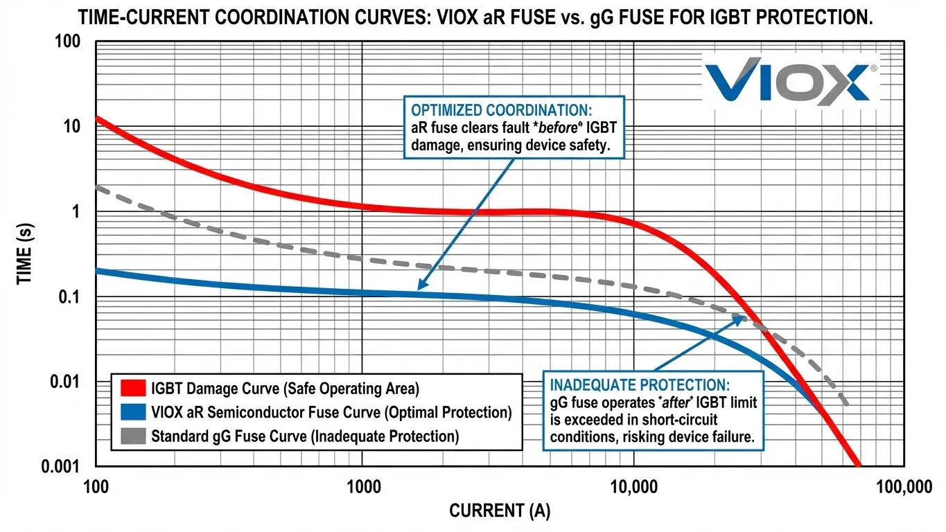
Standard “gG” or “gL” fuses, designed for cable protection, have melting times of 50-200ms at fault currents. This response is far too slow for semiconductor protection. By the time a standard fuse begins to melt, the IGBT junction temperature has already exceeded 175°C, causing thermal runaway and device destruction.
aR-Class Fuses: Purpose-Built for Semiconductors
Semiconductor protection requires aR-class fuses (IEC 60269-4 classification), where “a” indicates partial-range breaking capacity (short-circuit only) and “R” denotes rapid action optimized for semiconductor devices.
These specialized fuses feature:
- Silver-alloy fuse elements: Multiple parallel elements with carefully calibrated cross-sections ensure consistent, repeatable melting characteristics.
- High-purity quartz sand filling: Acts as arc-quenching medium, enabling rapid current interruption and preventing re-strike.
- Ceramic body construction: Provides mechanical strength and thermal stability for breaking capacities up to 100kA.
- Extremely low I²t rating: This is the critical parameter—the total let-through energy during fault clearing must be lower than the semiconductor’s thermal withstand capacity (typically measured in A²s).
Fuse Selection and Coordination
Proper fuse selection requires careful coordination with IGBT specifications:
Semiconductor Fuse Selection Criteria:
| Parameter | Selection Rule | Typical Value (120kW Charger) | Verification Method |
|---|---|---|---|
| Rated Current (In) | 1.2-1.5× continuous load | 250A-400A | Thermal calculation |
| Rated Voltage (Un) | ≥1.4× DC bus voltage | 1,000V DC | System design voltage |
| I²t Let-through | <50,000 A²s | Manufacturer datasheet | |
| Breaking Capacity (Icn) | ≥Maximum prospective fault | 50-100kA | Short-circuit study |
| Operating Class | aR (semiconductor) | aR per IEC 60269-4 | Standards compliance |
| Response Time | <5ms @ 10×In | <3ms typical | Time-current curves |
For a typical 150kW DC fast charger with 400A continuous output, the protection scheme would include:
- AC Input: 3× 630A gG-class fuses (grid protection)
- Rectifier Input: 3× 500A aR-class fuses (IGBT bridge protection)
- DC Link: 2× 400A aR-class DC fuses (bus protection)
- Output Stage: 2× 500A DC fuses with electronic pre-charge circuit
The VIOX Advantage: Integrated Protection Solutions
As a leading B2B manufacturer of electrical protection equipment, VIOX Electric provides comprehensive protection solutions specifically engineered for DC fast charging infrastructure. Our product portfolio addresses every protection requirement in modern EV charging stations:
VIOX DC Fast Charger Protection Portfolio:
- VSP-T1+T2 Series: Combined Type 1+2 SPDs rated 20-40kA, UL 1449 5th Edition and IEC 61643-11 certified
- VF-AR Series: Ultra-rapid aR semiconductor fuses, 100kA breaking capacity, IEC 60269-4 compliant
- VF-DC Series: DC-rated fuses for 1,000V/1,500V systems with bidirectional current interruption
- VDC-SPD Series: DC surge protection devices meeting IEC 61643-31 for post-rectifier protection
Each VIOX protection device is designed for the harsh operating environment of commercial charging stations: -40°C to +85°C temperature range, IP65 weather protection, and 20-year service life under normal conditions.
Our engineering team provides complete protection coordination studies, ensuring that SPDs and fuses work together as an integrated system rather than independent components. This coordination prevents nuisance tripping while guaranteeing that fault currents are interrupted before equipment damage occurs.
Implementation Best Practices
Installation Considerations
Proper installation is as critical as component selection:
SPD Installation:
- Mount as close as possible to protected equipment (minimize lead length)
- Use wire sizes per manufacturer specifications (typically 6-10 AWG)
- Ensure solid grounding connection with impedance <10Ω
- Install remote monitoring contacts for predictive maintenance
Fuse Installation:
- Use manufacturer-specified fuse holders rated for full fault current
- Verify adequate cooling air flow around fuses
- Implement fuse status monitoring (blown fuse indication)
- Maintain spare fuse inventory for rapid replacement
Maintenance and Testing
Protection devices require periodic verification:
SPD Maintenance:
- Visual inspection quarterly for damage or discoloration
- Verify remote status indicator functionality monthly
- Test leakage current annually (should be <1mA)
- Replace after major surge event (even if no visible damage)
Fuse Maintenance:
- Thermal imaging inspection semi-annually
- Verify fuse holder contact resistance (<50µΩ)
- Replace fuses showing any discoloration or signs of overheating
- Document all replacements for trend analysis
FAQ: DC Fast Charger Protection
Q: Can I use standard circuit breakers instead of semiconductor fuses for my DC charging station?
A: No. Standard circuit breakers have response times of 20-100ms, which is far too slow to protect IGBTs and other power semiconductors that fail in under 5ms during fault conditions. Semiconductor-specific aR-class fuses with <5ms clearing times are mandatory for protecting power conversion modules. Standard breakers should be used for input protection and load switching, not semiconductor protection.
Q: What’s the difference between Type 1 and Type 2 SPDs, and which do I need?
A: Type 1 SPDs handle direct lightning strikes (25kA, 10/350μs waveform) and are installed at service entrance. Type 2 SPDs protect against induced surges (40kA, 8/20μs waveform) and are installed at equipment level. Commercial DC fast chargers typically require both, or a combined Type 1+2 hybrid device. Outdoor installations with overhead power feeds mandatorily need Type 1 protection per NEC Article 625 and IEC 61851-23.
Q: How do I determine the correct fuse rating for my charging station’s power modules?
A: Select fuse rating at 1.2-1.5× the continuous load current, verify that fuse I²t let-through energy is less than the IGBT’s rated I²t (found in manufacturer datasheets), and ensure breaking capacity exceeds maximum prospective fault current from short-circuit study. Always coordinate with module manufacturer specifications—using oversized fuses eliminates protection, while undersized fuses cause nuisance trips.
Q: Do EV charging stations need both AC-side and DC-side surge protection?
A: Yes. AC-side SPDs (before the rectifier) protect against grid-sourced surges and lightning. DC-side SPDs (after the rectifier) are equally important because surges can be generated internally by switching operations, or can propagate from the vehicle side through the charging cable. IEC 61851-23 specifically requires DC-side surge protection rated for the system voltage (typically 1,000V DC).
Q: How often should protection devices be replaced, and what’s the lifecycle cost?
A: SPDs should be replaced after any major surge event (>80% of rated capacity) or when remote monitoring indicates degradation. Typical lifespan is 10-20 years in normal conditions. Semiconductor fuses should be replaced immediately after clearing a fault—they’re single-use protective devices. However, fuse replacement cost ($50-200 per fuse) is trivial compared to IGBT module replacement ($500-3,000) or charging station downtime ($200-500 per hour in lost revenue).
Q: Are there special requirements for DC fast chargers above 150kW?
A: High-power chargers (150-350kW) require enhanced protection due to higher fault current magnitudes. This includes: higher breaking capacity fuses (100kA minimum), parallel fuse arrangements with proper current sharing, enhanced cooling systems, and often redundant protection paths. Additionally, ultra-high-power chargers typically use 1,500V DC bus architecture, requiring appropriately rated protection devices. Always consult IEC 61851-23 and UL 2202 for specific power level requirements.
Conclusion: Protection as Investment, Not Expense
In DC fast charging infrastructure, protection devices aren’t auxiliary components—they’re integral to system reliability and financial viability. A single unprotected surge event can destroy $10,000-30,000 in equipment and cause days of downtime. Properly specified SPDs and semiconductor fuses, representing just 3-5% of total charger cost, provide insurance against these catastrophic failures.
The regulatory landscape increasingly mandates comprehensive protection. IEC 61851-23:2023 and updated UL 2202 requirements have strengthened surge protection specifications, making compliance non-optional for new installations. As the EV charging network expands into higher-power applications (350kW+ chargers for commercial vehicles), protection requirements will only become more stringent.
VIOX Electric’s engineering team provides complete protection solutions backed by 25+ years of experience in power distribution and protection systems. Our products meet all relevant international standards and are proven in thousands of commercial charging installations worldwide. Contact our technical sales team for site-specific protection coordination studies and product recommendations.
For technical specifications, installation guides, and protection coordination studies, visit viox.com or contact our applications engineering team. VIOX Electric—Protecting the infrastructure that powers tomorrow’s mobility.
