Na této stránce
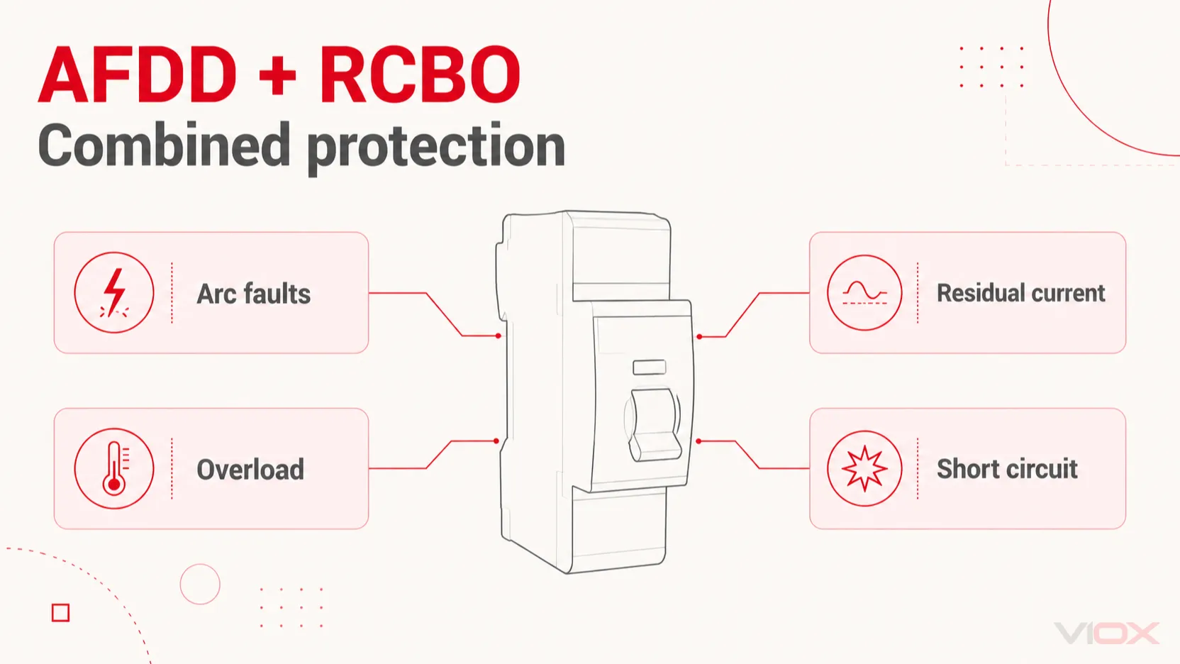
. AFDD RCBO kombinuje detektor obloukových poruch s proudovým chráničem s nadproudovou ochranou. U deklarované kombinované jednotky slouží detekce obloukových poruch, ochrana proti reziduálnímu proudu, ochrana proti přetížení a ochrana proti zkratu stejnému koncovému obvodu. Každá funkce reaguje na jiný stav poruchy.
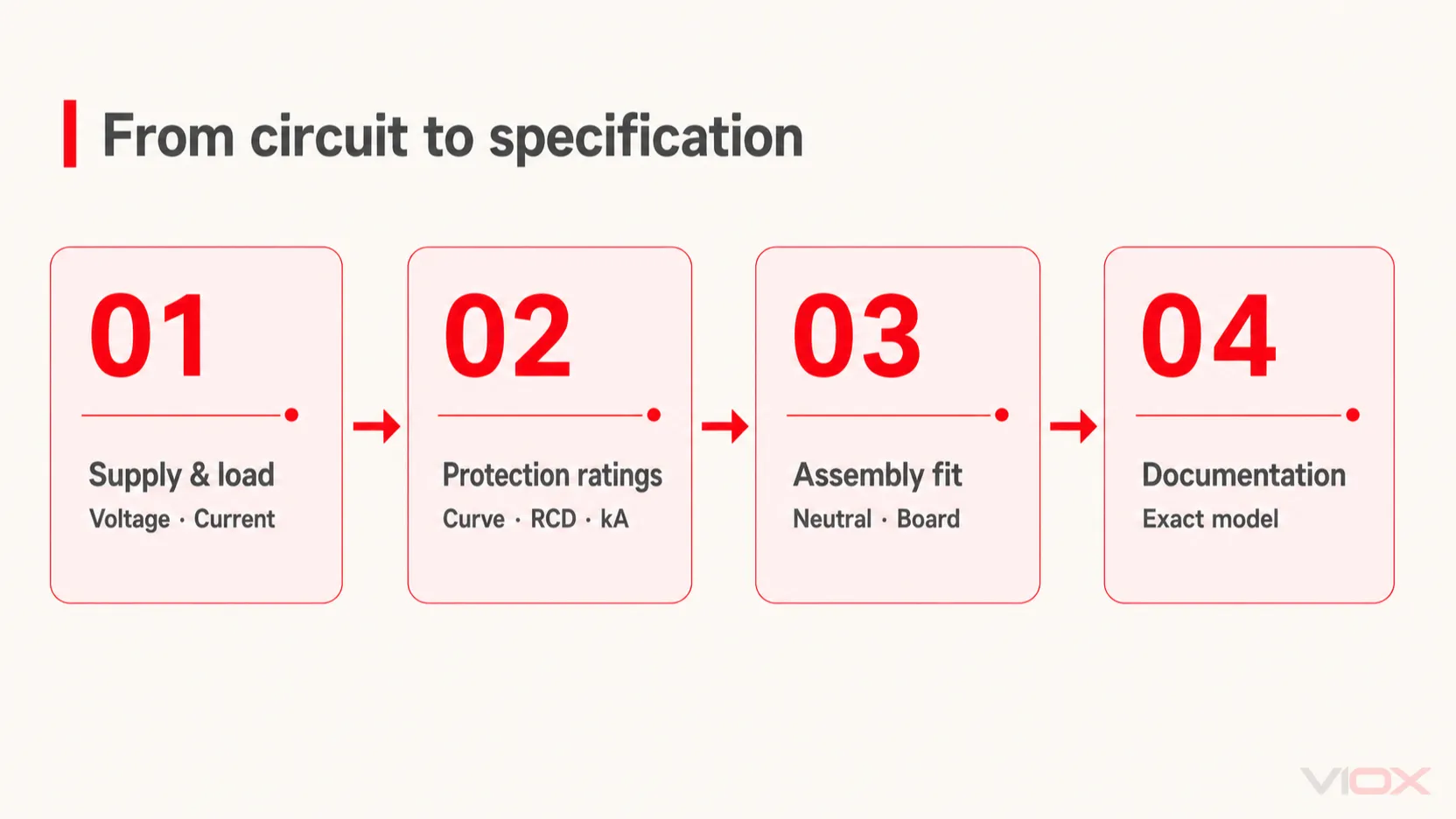
Pro výběr správného zařízení přiřaďte všechny tyto funkce k obvodu: napájecí napětí a frekvenci, jmenovitý proud In, vypínací charakteristiku, typ a citlivost reziduálního proudu, zkratovou odolnost, uspořádání nulového vodiče a kompatibilitu s rozváděčem. “AFDD + RCBO” popisuje kombinaci ochrany; nejedná se o úplnou specifikaci.
Klíčové poznatky
- Nebezpečný sériový oblouk může vzniknout bez dostatečného nadproudu nebo reziduálního proudu pro vybavení běžného RCBO.
- B nebo C popisuje nadproudovou charakteristiku; typ A popisuje detekci reziduálního proudu. Tato označení odpovídají na různé otázky.
- Jmenovitý proud v ampérech, citlivost v miliampérech a vypínací schopnost v kiloampérech jsou u tohoto zařízení samostatné limity.
- Kombinované zařízení musí odpovídat obvodu a deklarované sestavě rozváděče. Samotné fyzické upevnění na DIN lištu nestačí.
Pro orientaci v normách, zkoušení a souvisejících zařízeních viz co AFDD dělá a jak funguje.
Jak funguje kombinovaná ochrana
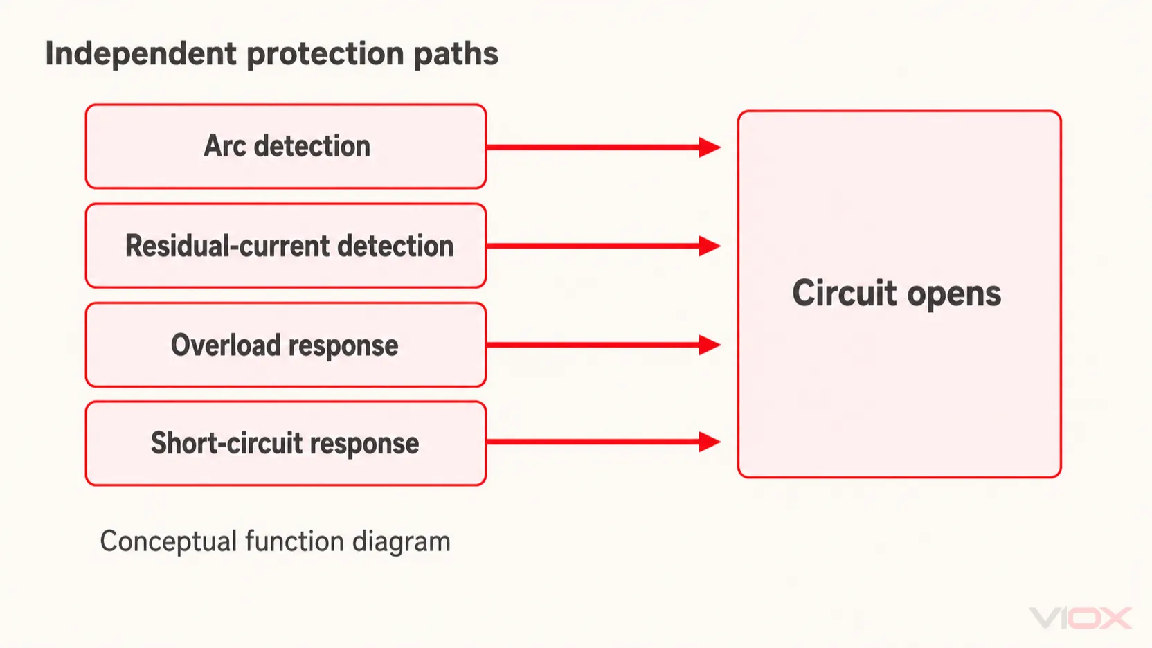
Ochranné funkce pracují nezávisle na sobě. Zařízení nečeká, až nastane oblouková porucha, svodový proud a přetížení současně. K vybavení obvodu může vést jakákoli kvalifikovaná porucha detekovaná kteroukoli z integrovaných ochranných funkcí.
Elektronika pro detekci oblouku vyhodnocuje elektrické signatury spojené s nebezpečným obloukem. Funkce reziduálního proudu detekuje nerovnováhu mezi odchozím a vracejícím se proudem ve sledovaných vodičích. Nadproudová funkce reaguje podle své časově-proudové charakteristiky: trvalé přetížení a vysoký zkratový proud vyžadují odlišné reakce.
Následující text je funkčním vysvětlením, nikoli schématem vnitřní konstrukce nebo zapojení svorek. Snímače, elektronika, vypínací mechanismus a uspořádání kontaktů závisí na konkrétním provedení výrobku. Norma IEC 62606 uznává různá konstrukční uspořádání AFDD, včetně integrace s jinými ochrannými zařízeními. Rozsah normy IEC 62606
| Poruchový stav | Relevantní funkce v kombinovaném AFDD RCBO | Co určuje provoz |
|---|---|---|
| Nebezpečný sériový nebo paralelní oblouk | Detekce obloukového zkratu | Detekční kritéria a deklarované provozní podmínky zařízení |
| Proud vracející se mimo sledované vodiče obvodu | Ochrana proti reziduálnímu proudu | Reziduální průběh, velikost a provozní charakteristika |
| Trvalý proud nad povolené zatížení obvodu | Ochrana proti přetížení | Jmenovitý proud a časově-proudová charakteristika s ohledem na podmínky instalace |
| Vysoký proud při zkratu | Ochrana proti zkratu | Poruchový proud, vypínací charakteristika a vypínací schopnost |
Proč funkce RCBO sama o sobě nemusí detekovat oblouk
Uvažujme zhoršující se spoj v sérii se zátěží. Jeho odpor může omezit proud obvodu, zatímco ve spoji vzniká oblouk. Odchozí a vracející se proudy mohou být stále v rovnováze. V takovém případě není zaručen ani velký nadproud, ani dostatečná nesymetrie reziduálního proudu.
To vysvětluje, proč přidání detekce oblouku může vyřešit mezeru v konvenční ochraně. Neznamená to, že AFDD detekuje každý přehřívající se spoj nebo zabrání každému elektrickému požáru. Kvalitní spoje, vhodné vodiče a ověření instalace zůstávají nezbytné. Tato Příručka pro elektrické instalace Schneider o ochraně AFDD vysvětluje její vztah ke konvenční ochraně koncových obvodů.
Paralelní poruchy mohou zahrnovat fázový a nulový vodič nebo fázový vodič a ochranné uzemnění. V závislosti na poruše může zareagovat také funkce nadproudu nebo reziduálního proudu. Nepředpokládejte, že každé vypnutí kombinovaného přístroje dokazuje obloukovou poruchu; použijte diagnostickou indikaci a pokyny daného modelu.
Co znamená “AFDD + RCBO” při objednávání
U integrovaného produktu tento výraz znamená, že výrobce poskytuje funkce detekce oblouku a RCBO společně v jednom deklarovaném přístroji. Samostatná jednotka pro detekci oblouku sestavená s ochranným přístrojem představuje jinou konstrukční cestu a musí využívat výrobcem deklarovanou kombinaci.
Znaménko plus neopravňuje ke kombinování libovolných produktů AFDD a RCBO. Rovněž nestanovuje spínání nulového vodiče, šířku modulu, přepěťovou ochranu ani certifikaci pro konkrétní trh.
Pokud je otázkou při nákupu, zda běžný RCBO a AFDD poskytují stejné funkce, použijte samostatné porovnání RCBO a AFDD. U integrovaného produktu je užitečným dalším krokem převod požadavků obvodu na jmenovité hodnoty.
Výběr přístroje na základě požadavků obvodu
Začněte návrhem obvodu a očekávaným chováním zátěže. Příručka společnosti Eaton pro selektivitu a koordinaci výslovně vyžaduje samostatné posouzení funkcí jističe, reziduálního proudu a AFDD v rámci kombinovaného přístroje.
| Vstupní údaje pro návrh | Pole pro specifikaci nebo ověření | Rozhodnutí o výběru |
|---|---|---|
| Uspořádání napájení | Jmenovité napětí, frekvence a podporovaná konfigurace obvodu | Odmítněte zařízení, které není určeno pro dané napájení |
| Návrhová zátěž a kapacita vodičů | Jmenovitý proud a příslušné snížení výkonu | Chraňte vodič při napájení zamýšlené zátěže |
| Rozběhový proud a podmínky smyčky poruchy | B/C nebo jiná deklarovaná nadproudová charakteristika | Zkontrolujte jak normální zapínací proud, tak požadované odpojení při poruše |
| Očekávaný průběh reziduálního proudu | Typ RCD | Přizpůsobte elektronice zátěže a příslušným požadavkům na instalaci |
| Požadovaná ochrana před reziduálním proudem | Jmenovitý reziduální pracovní proud, IΔn | Zvolte citlivost a koordinaci odpovídající danému obvodu |
| Předpokládaný zkratový proud | Vypínací schopnost a jakékoli dokumentované záložní uspořádání | Ověřte dostatečné přerušení v místě instalace |
| Požadavky na nulový vodič a odpojení | Konfigurace pólů a deklarované spínací chování | Potvrďte, které vodiče jsou spínány a chráněny |
| Konstrukce rozváděče | Řada zařízení, přípojnice, svorky, rozměry a tepelné podmínky | Ověřte kompatibilitu sestavy, nejen fyzické rozměry |
| Cílový trh a aplikace | Návody, prohlášení a příslušné certifikáty | Přiřaďte dokumenty k přesné objednané variantě |
Jmenovitý proud není vypínací schopnost
Proud v ampérech určuje schopnost zařízení přenášet jmenovitý proud za deklarovaných podmínek. Vypínací schopnost v kiloampérech popisuje jeho schopnost přerušit zkrat za příslušných zkušebních podmínek. Vyšší jmenovitý proud neřeší nedostatečnou vypínací schopnost.
Pro běžnou kontrolu ochrany proti přetížení projektant obvodu obvykle kontroluje níže uvedený vztah spolu s příslušnými požadavky na provozní proud a instalaci:
IB ≤ In ≤ Iz

IB = návrhový proud obvodu
In = jmenovitý proud ochranného přístroje
Iz = proudová zatížitelnost vodiče po aplikaci příslušných korekcí
Tento vztah sám o sobě nestačí pro dimenzování kabelů nebo koordinaci ochrany. Důležitý je také způsob instalace, seskupení, teplota, podmínky odpojení a energie poruchy. Tato příručka společnosti Schneider k hodnotám ochranných schémat vysvětluje podmínky ochrany proti přetížení.
Křivka B/C a typ A jsou odlišné klasifikace
Štítek jako “C16, typ A, 30 mA” obsahuje čtyři samostatné parametry. C označuje nadproudovou vypínací charakteristiku, 16 A je jmenovitý proud a typ A označuje schopnost detekce průběhu reziduálního proudu. Hodnota 30 mA je jmenovitý reziduální pracovní proud.
Výběr křivky C nezmění typ A na jiný typ reziduálního proudu. Stejně tak jistič s křivkou B není automaticky RCD typu B. Terminologii jističů a RCD je nutné posuzovat odděleně.
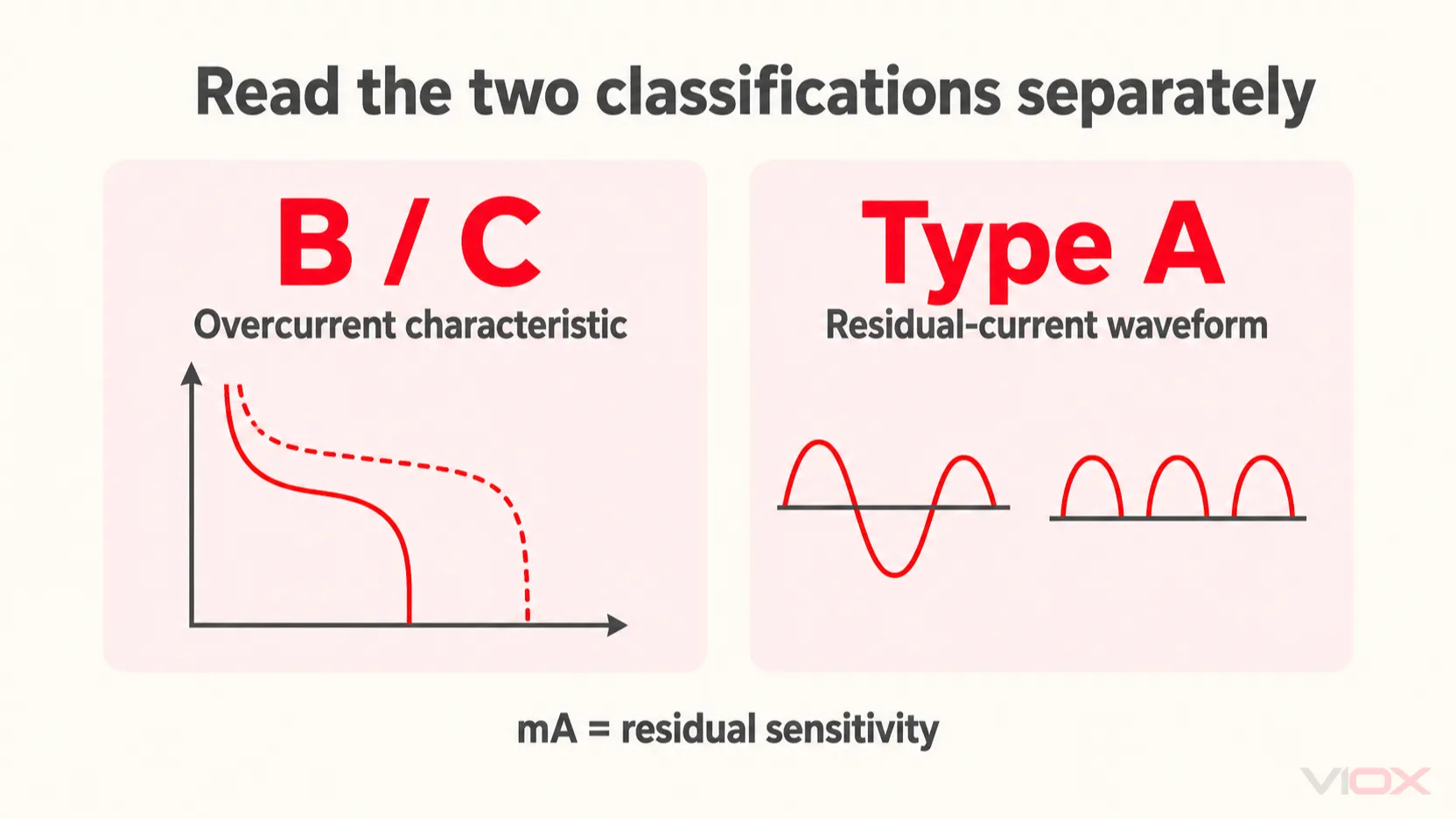
Výše uvedené křivky a průběhy jsou koncepčními ilustracemi, nikoliv časově-proudovými daty specifickými pro daný model nebo zkušebními průběhy.
Typ A pokrývá sinusové střídavé (AC) a pulzující stejnosměrné (DC) reziduální proudy v rámci svých specifikovaných podmínek. Nemělo by se předpokládat, že je vhodný pro každou zátěž, která může vytvářet vyhlazený stejnosměrný proud nebo komplexní průběhy reziduálního proudu. Při výběru funkce reziduálního proudu zkontrolujte pokyny k zařízení a požadavky na instalaci. Průvodce Schneider typy RCD
U nadproudové charakteristiky zvažte společně spouštěcí proud a dostupný poruchový proud. Změna charakteristiky pouze za účelem zastavení nechtěného vypínání může narušit požadovanou vypínací schopnost. Konzultujte přesná data časově-proudové charakteristiky.
Zkontrolujte uspořádání nulového vodiče a rozhraní rozváděče
Počet pólů a šířka modulu popisují různé věci. Kompaktní zařízení může mít konfiguraci 1P+N; jeho šířka vám neřekne, který pól má nadproudovou ochranu nebo jak je spínán nulový vodič.
Přečtěte si schéma zařízení a montážní pokyny. Potvrďte připojení nulového vodiče, povolený směr napájení, rozhraní přípojnic a deklarovanou kombinaci rozváděče/zařízení. Nevyvozujte tyto podrobnosti z fotografie čelního panelu nebo z uspořádání svorek jiné značky.
Na stránkách Průvodce výběrem jističů Schneider identifikuje instalační charakteristiky, prostředí a zátěže jako vstupy pro výběr. Pro AFDD RCBO platí tyto kontroly spolu s jeho doplňkovými detekčními funkcemi.
Kontrola vypracované specifikace
Následující text je hypotetický příklad prověření, nikoliv kompletní návrh instalace. Předpokládejme, že projektant již stanovil koncový obvod 240 V AC, 50 Hz s návrhovým proudem 18 A a korigovanou proudovou zatížitelností vodičů 25 A. Předpokládejme, že projekt vyžaduje ochranu před reziduálním proudem typu A, 30 mA a předpokládaný zkratový proud v místě zařízení je 4 kA.
| Položka prověření | Příklad posouzení | Co zbývá ověřit |
|---|---|---|
| Jmenovitý proud | Kandidát 20 A vyhovuje podmínce 18 A ≤ 20 A ≤ 25 A | Úplné podmínky ochrany proti přetížení a ochrany vodičů |
| Vypínací schopnost | Zařízení deklarované na 6 kA pro příslušné napětí a normu překračuje předpokládané 4 kA | Posouzení skutečné poruchy a veškeré požadavky na koordinaci |
| Reziduální ochrana | Typ A, 30 mA odpovídá stanovenému požadavku na návrh | Vhodnost pro skutečně připojené zařízení a předřazenou ochranu |
| Nadproudová charakteristika | B nebo C nelze zvolit pouze na základě zatěžovacího proudu | Kontroly zapínacího proudu a odpojení při poruše |
| Kompatibilita rozváděče | Na základě těchto elektrických hodnot nelze učinit žádné rozhodnutí | Schválené rozhraní, rozměry, uspořádání nulového vodiče a tepelné podmínky |
Výsledkem je kandidátní specifikace: 240 V AC, 50 Hz, 20 A, typ A, 30 mA, s dostatečnou deklarovanou vypínací schopností. Je stále neúplná, dokud nebudou vyřešeny charakteristika, rozhraní desky a zbývající konstrukční kontroly. Proto uvádění pouze “20 A AFDD RCBO” ponechává důležitá rozhodnutí nezodpovězená.
Normy a dokumenty, které mají odpovídat objednávce
IEC/EN 62606 se týká zařízení pro detekci oblouku, zatímco IEC/EN 61009-1 je relevantní pro funkci RCBO. Jejich uvedení v katalogu samo o sobě není důkazem nezávislé certifikace nebo povolení k instalaci zařízení v každé jurisdikci.
Vyžádejte si technický list, návod k instalaci a prohlášení pro konkrétní model a jmenovité hodnoty. Pokud projekt vyžaduje certifikát, zkontrolujte jeho vydavatele, rozsah, zahrnuté varianty a příslušné vydání normy. Produktové normy a místní pravidla instalace mají odlišné úkoly; Průvodce rozsahem a důkazy podle IEC 62606 vysvětluje tento rozdíl.
Dokumentace by měla rovněž identifikovat postup testovacího tlačítka a veškeré diagnostické indikace. Testovací tlačítko musí být používáno v souladu s pokyny výrobce; jeho přítomnost neověřuje kompletní instalaci ani nestanovuje univerzální provozní zkoušku pro každou ochrannou funkci.
Aplikace výběru na zařízení VIOX
Aktuální Produktová řada AFDD VIOX uvádí VAF1-40 a VAF3-40M jako zařízení kombinující ochranu proti obloukovým poruchám, reziduálnímu proudu typu A, přetížení a zkratu. Publikovaný sortiment zahrnuje jmenovité proudy 6–40 A, charakteristiky B/C a reziduální citlivosti 10/30 mA pro obvody 240 V AC, 50 Hz, se stanovenou konfigurací 1P+N a vypínací schopností 6 kA.
VAF3-40M je popsán jako magnetická verze. Samotný tento název není důkazem lepší detekce oblouku, odlišného chování nulového vodiče nebo jiného způsobu instalace. Pro vyřešení konstrukčních detailů použijte přesnou dokumentaci k modelu.
Pro vyžádání vhodné varianty zašlete podrobnosti o napájení, návrhový proud, požadovanou vypínací charakteristiku, typ a citlivost reziduálního proudu, předpokládaný poruchový proud, značku/řadu rozváděče, cílový trh a množství na adresu [email protected]. Přiložte požadovanou dokumentaci a veškeré požadavky na označení OEM, aby nabízené zařízení mohlo být zkontrolováno oproti kompletní specifikaci.