اس صفحے پر
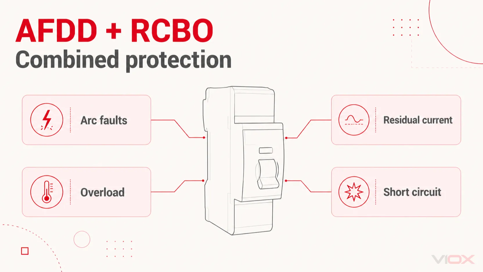
ایک AFDD RCBO ایک آرک فالٹ ڈیٹیکشن ڈیوائس کو اوور کرنٹ پروٹیکشن کے ساتھ ایک ریزیڈول کرنٹ سرکٹ بریکر کے ساتھ ملاتا ہے۔ ایک ڈکلیئرڈ مشترکہ یونٹ میں، آرک فالٹ ڈیٹیکشن، ریزیڈول کرنٹ پروٹیکشن، اوورلوڈ پروٹیکشن اور شارٹ سرکٹ پروٹیکشن ایک ہی فائنل سرکٹ کے لیے کام کرتے ہیں۔ ہر فنکشن ایک مختلف فالٹ کنڈیشن پر ردعمل ظاہر کرتا ہے۔.
صحیح ڈیوائس کا انتخاب کرنے کے لیے، ان تمام فنکشنز کو سرکٹ کے مطابق بنائیں: سپلائی وولٹیج اور فریکوئنسی، ریٹیڈ کرنٹ، اوور کرنٹ کرو، ریزیڈول کرنٹ کی قسم اور حساسیت، شارٹ سرکٹ کی گنجائش، نیوٹرل کا انتظام اور ڈسٹری بیوشن بورڈ کی مطابقت۔ “AFDD + RCBO” تحفظ کے امتزاج کو بیان کرتا ہے؛ یہ مکمل تفصیلات نہیں ہے۔.
کلیدی ٹیک ویز
- ایک خطرناک سیریز آرک بغیر اتنے اوور کرنٹ یا ریزیڈول کرنٹ کے پیدا ہو سکتی ہے جو ایک عام RCBO کو آپریٹ کر سکے۔.
- B یا C اوور کرنٹ کی خصوصیت کو بیان کرتا ہے؛ ٹائپ A ریزیڈول کرنٹ ڈیٹیکشن کو بیان کرتا ہے۔ یہ لیبلز مختلف سوالات کے جواب دیتے ہیں۔.
- ڈیوائس کی ایمپیئر ریٹنگ، ملی ایمپیئر حساسیت اور کلو ایمپیئر بریکنگ کیپیسٹی الگ الگ حدود ہیں۔.
- ایک مشترکہ ڈیوائس کو سرکٹ اور اعلان کردہ بورڈ اسمبلی کے مطابق ہونا چاہیے۔ صرف DIN-rail پر فٹ ہونا کافی نہیں ہے۔.
معیارات، ٹیسٹنگ اور متعلقہ ڈیوائسز کے بارے میں رہنمائی کے لیے، ملاحظہ کریں AFDD کیا کرتا ہے اور یہ کیسے کام کرتا ہے.
مشترکہ تحفظ کیسے کام کرتا ہے
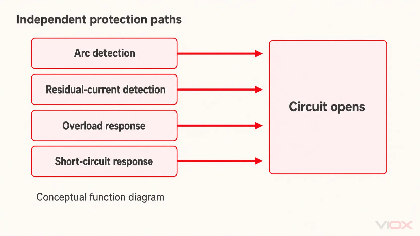
تحفظ کے افعال ایک ساتھ کام کرتے ہیں۔ ڈیوائس آرک فالٹ، ارتھ لیکیج اور اوورلوڈ کے ایک ساتھ ہونے کا انتظار نہیں کرتی۔ کسی بھی شامل حفاظتی فنکشن کے ذریعے پتہ چلنے والا کوئی بھی اہل فالٹ سرکٹ کو کھولنے کا سبب بن سکتا ہے۔.
آرک ڈیٹیکشن الیکٹرانکس خطرناک آرکنگ سے وابستہ برقی دستخطوں کا جائزہ لیتی ہے۔ بقایا کرنٹ (residual-current) فنکشن مانیٹر کیے گئے کنڈکٹرز میں جانے والے اور واپس آنے والے کرنٹ کے درمیان عدم توازن کا پتہ لگاتا ہے۔ اوور کرنٹ فنکشن اپنی ٹائم-کرنٹ خصوصیات کے مطابق ردعمل ظاہر کرتا ہے: مسلسل اوورلوڈ اور ہائی شارٹ سرکٹ کرنٹ کے لیے مختلف ردعمل درکار ہوتے ہیں۔.
ذیل میں ایک فنکشنل وضاحت دی گئی ہے، نہ کہ اندرونی ساخت یا ٹرمینل ڈایاگرام۔ سینسرز، الیکٹرانکس، ٹرپ میکانزم اور کانٹیکٹ کی ترتیب پروڈکٹ کے درست ڈیزائن پر منحصر ہے۔ IEC 62606 مختلف AFDD تعمیراتی انتظامات کو تسلیم کرتا ہے، بشمول دیگر حفاظتی ڈیوائسز کے ساتھ انضمام۔. IEC 62606 کا دائرہ کار
| فالٹ کی حالت | مشترکہ AFDD RCBO میں متعلقہ فنکشن | آپریشن کا تعین کیا کرتا ہے |
|---|---|---|
| خطرناک سیریز یا متوازی آرکنگ | آرک فالٹ ڈیٹیکشن | ڈیوائس کے سراغ لگانے کے معیارات اور اعلان کردہ آپریٹنگ حالات |
| مانیٹر شدہ سرکٹ کنڈکٹرز سے باہر واپس آنے والا کرنٹ | بقایا کرنٹ تحفظ | بقایا ویوفارم، شدت اور آپریٹنگ خصوصیات |
| سرکٹ کے مجاز لوڈنگ سے اوپر مسلسل کرنٹ | اوورلوڈ تحفظ | ریٹیڈ کرنٹ اور ٹائم-کرنٹ خصوصیات، تنصیب کے حالات کو مدنظر رکھتے ہوئے |
| شارٹ سرکٹ سے پیدا ہونے والا ہائی کرنٹ | شارٹ سرکٹ تحفظ | فالٹ کرنٹ، ٹرپ کی خصوصیات اور انٹرپٹنگ کیپیسٹی |
صرف RCBO کا فنکشن آرک (arc) کو کیوں نہیں پکڑ سکتا
ایک لوڈ کے ساتھ سیریز میں خراب ہوتے ہوئے کنکشن پر غور کریں۔ اس کی مزاحمت سرکٹ کرنٹ کو محدود کر سکتی ہے جبکہ کنکشن میں آرکنگ ہو رہی ہو۔ آؤٹ گوئنگ اور ریٹرننگ کرنٹ اب بھی متوازن ہو سکتے ہیں۔ اس صورت میں، نہ تو بڑے اوور کرنٹ اور نہ ہی کافی ریزیڈول کرنٹ کے عدم توازن کی ضمانت دی جا سکتی ہے۔.
یہ وضاحت کرتا ہے کہ آرک ڈیٹیکشن کا اضافہ روایتی تحفظ میں موجود خلا کو کیسے پُر کر سکتا ہے۔ اس کا مطلب یہ نہیں ہے کہ AFDD ہر گرم کنکشن کا پتہ لگا لیتا ہے یا ہر برقی آگ کو روک دیتا ہے۔ مضبوط کنکشن، مناسب کنڈکٹرز اور تنصیب کی تصدیق اب بھی ضروری ہے۔ AFDD تحفظ پر Schneider الیکٹریکل انسٹالیشن گائیڈ روایتی فائنل سرکٹ پروٹیکشن کے ساتھ اس کے تعلق کی وضاحت کرتی ہے۔.
متوازی فالٹس میں لائن اور نیوٹرل یا لائن اور ارتھ شامل ہو سکتے ہیں۔ فالٹ کی نوعیت کے لحاظ سے، اوور کرنٹ یا بقایا کرنٹ (residual-current) کا فنکشن بھی ردعمل ظاہر کر سکتا ہے۔ یہ فرض نہ کریں کہ مشترکہ ڈیوائس کا ہر ٹرپ آرک فالٹ کو ثابت کرتا ہے؛ ماڈل کی تشخیصی نشاندہی اور ہدایات کا استعمال کریں۔.
آرڈر کرتے وقت “AFDD + RCBO” کا کیا مطلب ہے
ایک مربوط پروڈکٹ کے لیے، اس جملے کا مطلب یہ ہے کہ مینوفیکچرر آرک ڈیٹیکشن اور RCBO کے فنکشنز کو ایک ہی ڈیوائس میں فراہم کرتا ہے۔ ایک حفاظتی ڈیوائس کے ساتھ اسمبل کی گئی الگ آرک ڈیٹیکشن یونٹ ایک مختلف تعمیراتی طریقہ ہے اور اس کے لیے مینوفیکچرر کی طرف سے اعلان کردہ امتزاج کا استعمال لازمی ہے۔.
جمع (+) کا نشان کسی بھی من مانی AFDD اور RCBO پروڈکٹس کو ملانے کی اجازت نہیں دیتا۔ یہ نیوٹرل سوئچنگ، ماڈیول کی چوڑائی، سرج پروٹیکشن یا کسی خاص مارکیٹ کے لیے سرٹیفیکیشن کو بھی قائم نہیں کرتا۔.
اگر خریداری کا سوال یہ ہے کہ کیا ایک عام RCBO اور ایک AFDD ایک جیسے فنکشنز فراہم کرتے ہیں، تو الگ RCBO بمقابلہ AFDD موازنہ. کا استعمال کریں۔ مربوط پروڈکٹ کے لیے، اگلا مفید قدم سرکٹ کی ضروریات کو ریٹنگز میں تبدیل کرنا ہے۔.
سرکٹ کی ضروریات کے مطابق ڈیوائس کا انتخاب کریں
سرکٹ ڈیزائن اور متوقع لوڈ کے رویے سے آغاز کریں۔ ایٹن (Eaton) کی سلیکٹیوٹی اور کوآرڈینیشن گائیڈ واضح طور پر اپنے مشترکہ ڈیوائس میں سرکٹ بریکر، ریزیڈول کرنٹ اور AFDD کے افعال کا الگ الگ جائزہ لینے کا مطالبہ کرتی ہے۔.
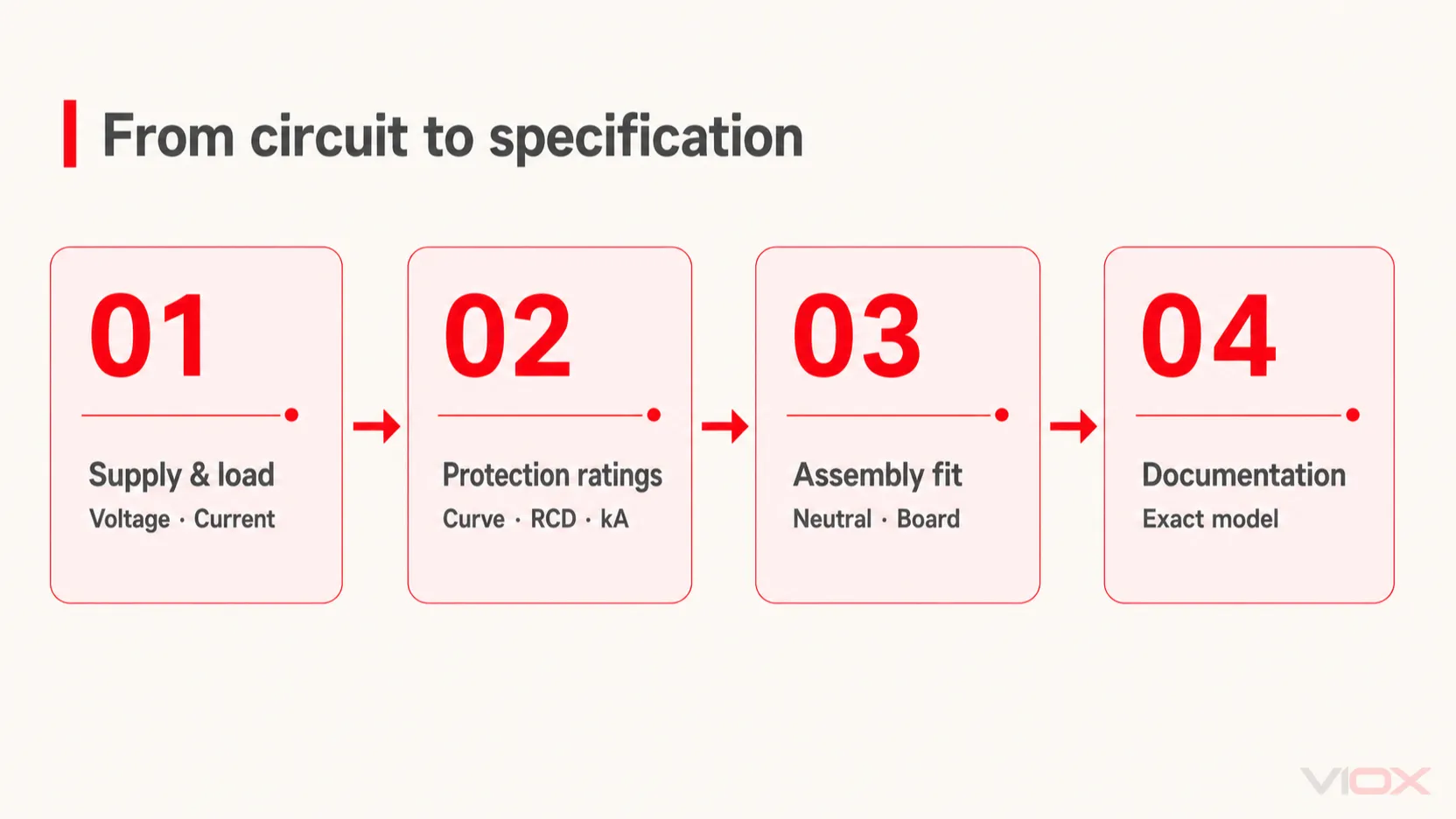
| ڈیزائن ان پٹ | مخصوص یا تصدیق کرنے کے لیے فیلڈ | انتخاب کا فیصلہ |
|---|---|---|
| سپلائی کا انتظام | ریٹیڈ وولٹیج، فریکوئنسی اور معاون سرکٹ کنفیگریشن | ایسی ڈیوائس کو مسترد کریں جو سپلائی کے لیے ظاہر نہ کی گئی ہو |
| ڈیزائن لوڈ اور کنڈکٹر کی گنجائش | ریٹڈ کرنٹ اور قابل اطلاق ڈی ریٹنگ | مطلوبہ لوڈ فراہم کرتے ہوئے کنڈکٹر کی حفاظت کریں |
| اسٹارٹنگ کرنٹ اور فالٹ لوپ کی شرائط | B/C یا دیگر اعلان کردہ اوور کرنٹ خصوصیات | عام ان رش (inrush) اور درکار فالٹ ڈس کنکشن دونوں کو چیک کریں |
| متوقع بقایا کرنٹ (residual-current) ویوفارم | RCD کی قسم | لوڈ الیکٹرانکس اور قابل اطلاق تنصیب کے تقاضوں سے مطابقت پیدا کریں |
| مطلوبہ بقایا کرنٹ (residual current) سے تحفظ | شرح شدہ بقایا آپریٹنگ کرنٹ، IΔn | سرکٹ کے مطابق حساسیت اور کوآرڈینیشن کا انتخاب کریں |
| متوقع شارٹ سرکٹ کرنٹ | بریکنگ کیپیسٹی اور کوئی بھی دستاویزی بیک اپ انتظام | انسٹالیشن پوائنٹ پر مناسب انٹرپشن کی تصدیق کریں |
| نیوٹرل اور آئسولیشن کی ضروریات | پول کنفیگریشن اور ڈکلیئرڈ سوئچنگ رویہ | تصدیق کریں کہ کون سے کنڈکٹرز سوئچ اور محفوظ کیے گئے ہیں |
| ڈسٹری بیوشن بورڈ کی تعمیر | ڈیوائس سیریز، بس بار، ٹرمینلز، طول و عرض اور تھرمل حالات | اسمبلی کی مطابقت کی تصدیق کریں، صرف جسمانی فٹنگ کی نہیں |
| منزل مقصود مارکیٹ اور اطلاق | ہدایات، اعلانات اور قابل اطلاق سرٹیفکیٹس | دستاویزات کو آرڈر کیے گئے درست ویرینٹ سے میچ کریں |
ریٹیڈ کرنٹ بریکنگ کیپیسٹی نہیں ہے
ایمپیئرز میں کرنٹ ڈیوائس کی اعلان کردہ حالات کے تحت ریٹیڈ لوڈ-کرنٹ کی صلاحیت کی نشاندہی کرتا ہے۔ کلو ایمپیئرز میں بریکنگ کیپیسٹی قابل اطلاق ٹیسٹ کے حالات کے تحت شارٹ سرکٹ کو منقطع کرنے کی اس کی صلاحیت کو بیان کرتی ہے۔ بڑی ایمپیئر ریٹنگ ناکافی بریکنگ کیپیسٹی کا حل نہیں ہے۔.
روایتی اوورلوڈ-پروٹیکشن چیک کے لیے، سرکٹ ڈیزائنر عام طور پر نیچے دیے گئے تعلق کی جانچ کرتا ہے، ساتھ ہی قابل اطلاق آپریٹنگ-کرنٹ اور تنصیب کی ضروریات کے مطابق:
IB ≤ In ≤ Iz

IB = سرکٹ ڈیزائن کرنٹ
In = حفاظتی ڈیوائس کا ریٹیڈ کرنٹ
Iz = قابل اطلاق اصلاحات کے بعد کنڈکٹر کی کرنٹ لے جانے کی صلاحیت
یہ تعلق اکیلے کیبل سائزنگ یا پروٹیکشن کوآرڈینیشن کو مکمل نہیں کرتا ہے۔ تنصیب کا طریقہ، گروپنگ، درجہ حرارت، منقطع ہونے کی شرائط اور فالٹ انرجی بھی اہمیت رکھتے ہیں۔ پروٹیکٹو اسکیم ویلیوز کے لیے شنائیڈر گائیڈ اوورلوڈ پروٹیکشن کی شرائط کی وضاحت کرتی ہے۔.
B/C کرو اور ٹائپ A مختلف درجہ بندیاں ہیں
ایک لیبل جیسے کہ “C16, Type A, 30 mA” چار الگ الگ پیرامیٹرز پر مشتمل ہوتا ہے۔ C اوور کرنٹ کرو کی نشاندہی کرتا ہے، 16 A ریٹیڈ کرنٹ ہے، اور ٹائپ A بقایا کرنٹ (residual-current) ویوفارم کی صلاحیت کی نشاندہی کرتا ہے۔ 30 mA کی قدر ریٹیڈ ریزیڈول آپریٹنگ کرنٹ ہے۔.
C کرو کا انتخاب کرنے سے ٹائپ A کسی اور ریزیڈول کرنٹ ٹائپ میں تبدیل نہیں ہوتا ہے۔ اسی طرح، ایک B-کرو بریکر خود بخود ٹائپ B RCD نہیں بن جاتا۔ سرکٹ بریکر اور RCD کی اصطلاحات کو الگ الگ پڑھا جانا چاہیے۔.
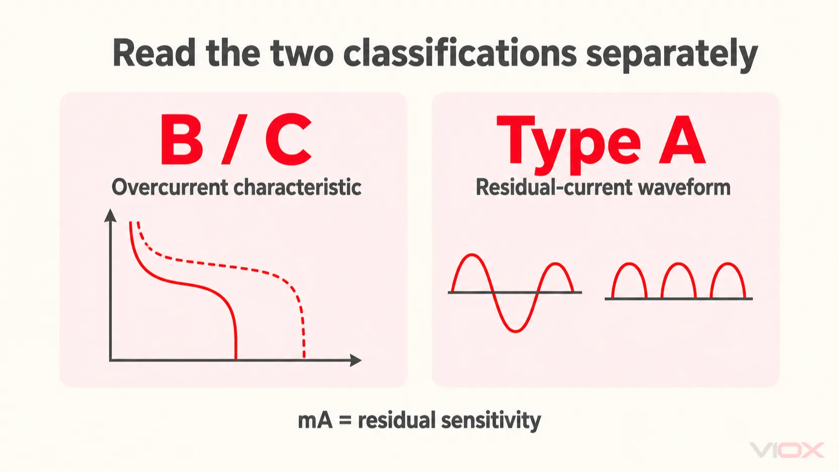
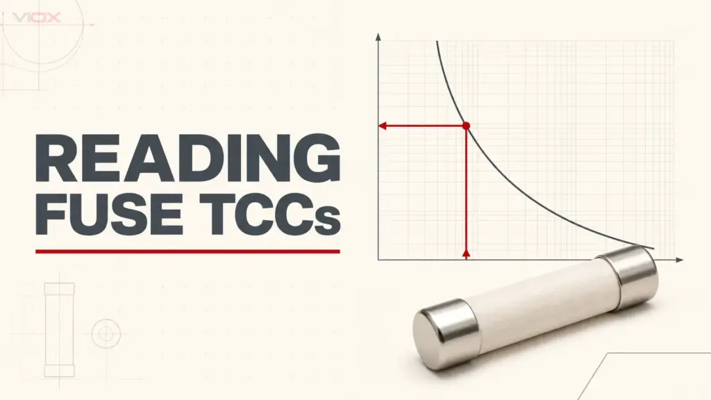
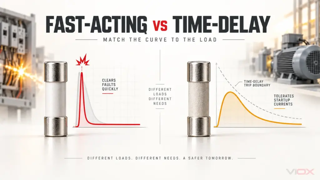
اوپر دیے گئے کروز اور ویوفارمز تصوراتی خاکے ہیں، نہ کہ ماڈل کے لیے مخصوص ٹائم-کرنٹ ڈیٹا یا ٹیسٹ ویوفارمز۔.
Type A اپنی مخصوص شرائط کے اندر sinusoidal AC اور pulsating DC بقایا کرنٹ کا احاطہ کرتا ہے۔ اسے ہر اس لوڈ کے لیے موزوں نہیں سمجھا جانا چاہیے جو ہموار DC یا پیچیدہ بقایا ویوفارمز پیدا کر سکتا ہے۔ بقایا کرنٹ فنکشن کا انتخاب کرتے وقت آلات کی ہدایات اور تنصیب کی ضروریات کو چیک کریں۔. RCD اقسام کے لیے شنائیڈر گائیڈ
اوور کرنٹ کرو کے لیے، اسٹارٹ اپ کرنٹ اور دستیاب فالٹ کرنٹ پر ایک ساتھ غور کریں۔ صرف غیر ضروری ٹرپس کو روکنے کے لیے کرو کو تبدیل کرنا مطلوبہ ڈس کنکشن کی کارکردگی کو کمزور کر سکتا ہے۔ درست ٹائم-کرنٹ ڈیٹا سے رجوع کریں۔.
نیوٹرل ارینجمنٹ اور بورڈ انٹرفیس کو چیک کریں
پول کی تعداد اور ماڈیول کی چوڑائی مختلف چیزوں کو بیان کرتی ہے۔ ایک کومپیکٹ ڈیوائس 1P+N کنفیگریشن کی حامل ہو سکتی ہے؛ اس کی چوڑائی یہ نہیں بتاتی کہ کس پول میں اوور کرنٹ پروٹیکشن ہے یا نیوٹرل کو کیسے سوئچ کیا جاتا ہے۔.
ڈیوائس کا ڈایاگرام اور اسمبلی کی ہدایات پڑھیں۔ نیوٹرل کنکشنز، سپلائی کی اجازت یافتہ سمت، بس بار انٹرفیس اور ڈیکلیئرڈ بورڈ/ڈیوائس کے امتزاج کی تصدیق کریں۔ ان تفصیلات کا اندازہ سامنے کی تصویر یا کسی دوسرے برانڈ کے ٹرمینل لے آؤٹ سے نہ لگائیں۔.
دی شنائیڈر سرکٹ بریکر سلیکشن گائیڈ تنصیب کی خصوصیات، ماحول اور لوڈز کی بطور سلیکشن ان پٹ شناخت کرتا ہے۔ AFDD RCBO کے لیے، وہ چیکس اس کے اضافی ڈیٹیکشن فنکشنز کے ساتھ لاگو ہوتے ہیں۔.
ایک کام شدہ تفصیلات کی جانچ
ذیل میں ایک فرضی اسکریننگ کی مثال دی گئی ہے، نہ کہ مکمل تنصیبی ڈیزائن۔ فرض کریں کہ ایک ڈیزائنر نے پہلے ہی 240 V AC، 50 Hz کا فائنل سرکٹ قائم کر لیا ہے جس کا ڈیزائن کرنٹ 18 A اور کنڈکٹر کی درست شدہ گنجائش 25 A ہے۔ فرض کریں کہ پروجیکٹ کے لیے Type A، 30 mA بقایا کرنٹ سے تحفظ درکار ہے اور ڈیوائس پر متوقع شارٹ سرکٹ کرنٹ 4 kA ہے۔.
| اسکریننگ آئٹم | مثالی تشخیص | تصدیق کے لیے کیا باقی ہے |
|---|---|---|
| شرح شدہ کرنٹ | ایک 20 A کا امیدوار 18 A ≤ 20 A ≤ 25 A کو پورا کرتا ہے | مکمل اوورلوڈ اور کنڈکٹر سے تحفظ کی شرائط |
| توڑنے کی صلاحیت | قابل اطلاق وولٹیج اور معیار کے لیے 6 kA پر اعلان کردہ ڈیوائس، فرض کردہ 4 kA سے زیادہ ہے | اصل فالٹ کا تخمینہ اور کوآرڈینیشن کی کوئی بھی ضروریات |
| بقایا کرنٹ سے تحفظ | Type A، 30 mA بیان کردہ ڈیزائن کی ضروریات سے مطابقت رکھتا ہے | اصل منسلک آلات اور اپ اسٹریم تحفظ کے لیے موزونیت |
| اوور کرنٹ کرو | صرف لوڈ کرنٹ کی بنیاد پر B یا C کا انتخاب نہیں کیا جا سکتا | انرش (Inrush) اور فالٹ ڈس کنکشن کی جانچ |
| بورڈ کی مطابقت | صرف ان برقی اقدار کی بنیاد پر کوئی فیصلہ نہیں کیا جا سکتا | منظور شدہ انٹرفیس، طول و عرض، نیوٹرل کی ترتیب اور تھرمل حالات |
نتیجہ ایک امیدوار تفصیلات ہے: 240 V AC، 50 Hz، 20 A، ٹائپ A، 30 mA، کافی ڈکلیئرڈ بریکنگ کیپیسٹی کے ساتھ۔ یہ تب تک نامکمل ہے جب تک کہ کرو، بورڈ انٹرفیس اور باقی ڈیزائن چیکس حل نہ ہو جائیں۔ یہی وجہ ہے کہ صرف “20 A AFDD RCBO” کا حوالہ دینا اہم انتخاب کو غیر جوابدہ چھوڑ دیتا ہے۔.
آرڈر سے مطابقت رکھنے والے معیارات اور دستاویزات
IEC/EN 62606 آرک ڈیٹیکشن ڈیوائس سے متعلق ہے، جبکہ IEC/EN 61009-1 کا تعلق RCBO فنکشن سے ہے۔ کیٹلاگ میں ان کا ظاہر ہونا بذات خود آزادانہ سرٹیفیکیشن یا ہر دائرہ اختیار میں ڈیوائس کو انسٹال کرنے کی اجازت کا ثبوت نہیں ہے۔.
عین ماڈل اور ریٹنگ کے لیے ڈیٹا شیٹ، تنصیب کی ہدایات اور اعلانات طلب کریں۔ جہاں پروجیکٹ کو سرٹیفکیٹ کی ضرورت ہو، وہاں اس کے جاری کنندہ، دائرہ کار، کورڈ ویریئنٹس اور متعلقہ معیاری ایڈیشن کو چیک کریں۔ پروڈکٹ کے معیارات اور مقامی تنصیب کے قواعد کے کام مختلف ہوتے ہیں؛ IEC 62606 کا دائرہ کار اور شواہد کی گائیڈ اس فرق کی وضاحت کرتی ہے۔.
دستاویزی کارروائی میں ٹیسٹ بٹن کے طریقہ کار اور کسی بھی تشخیصی اشارے کی بھی نشاندہی ہونی چاہیے۔ ٹیسٹ بٹن کا استعمال مینوفیکچرر کی ہدایات کے مطابق کیا جانا چاہیے؛ اس کی موجودگی مکمل تنصیب کی تصدیق نہیں کرتی اور نہ ہی ہر حفاظتی فنکشن کے لیے عالمی فیلڈ ٹیسٹ قائم کرتی ہے۔.
VIOX ڈیوائسز پر انتخاب کا اطلاق
کرنٹ VIOX AFDD پروڈکٹ رینج VAF1-40 اور VAF3-40M کو ایسی ڈیوائسز کے طور پر درج کرتا ہے جو آرک فالٹ، ٹائپ A ریزیڈول کرنٹ، اوورلوڈ اور شارٹ سرکٹ سے تحفظ کو یکجا کرتی ہیں۔ شائع شدہ رینج میں 6–40 A ریٹنگز، B/C خصوصیات اور 240 V AC، 50 Hz سرکٹس کے لیے 10/30 mA ریزیڈول حساسیت شامل ہے، جس میں 1P+N کنفیگریشن اور 6 kA بریکنگ ریٹنگ بیان کی گئی ہے۔.
VAF3-40M کو مقناطیسی ورژن کے طور پر بیان کیا گیا ہے۔ صرف یہ نام بہتر آرک ڈیٹیکشن، مختلف نیوٹرل رویے یا تنصیب کے مختلف طریقہ کار کا ثبوت نہیں ہے۔ تعمیراتی تفصیلات کو حل کرنے کے لیے درست ماڈل دستاویزات کا استعمال کریں۔.
مناسب ویرینٹ کی درخواست کرنے کے لیے، سپلائی کی تفصیلات، ڈیزائن کرنٹ، مطلوبہ کرو، ریزیڈول کرنٹ کی قسم اور حساسیت، متوقع فالٹ کرنٹ، بورڈ میک/سیریز، منزل مقصود مارکیٹ اور مقدار بھیجیں [email protected]. ۔ مطلوبہ دستاویزات اور کوئی بھی OEM لیبلنگ کی ضروریات شامل کریں تاکہ پیش کردہ ڈیوائس کو مکمل تفصیلات کے مطابق جانچا جا سکے۔.