
In electrical insulation design, creepage distance is the shortest path between two conductive parts measured along the surface of an insulating material. Unlike clearance—which is the shortest distance through air—creepage accounts for the fact that current leakage and surface tracking do not always travel through open space. In humid, dusty, or polluted conditions, the surface of an insulator often becomes the path of least resistance.
That distinction has real engineering consequences. A product can have adequate air clearance and still fail in service if the creepage distance along its insulating surfaces is too short. That is why standards for electrical safety, from IEC 60664-1 to IEC 62368-1, require engineers to evaluate both creepage and clearance as separate parameters with separate requirements.
This guide covers what creepage distance is, how it differs from clearance, what factors determine the required value, how to measure it correctly, and what mistakes to avoid in design and inspection.
Key Takeaways
- Creepage distance is the shortest path between two conductive parts measured along the surface of solid insulation—not through air.
- Clearance is the shortest straight-line distance between conductive parts through air. Both must be evaluated independently.
- The required creepage distance depends on working voltage, insulation type, pollution degree, material group (CTI), and overvoltage category.
- In environments with humidity, condensation, dust, or conductive contamination, surface leakage risk increases significantly.
- Correct creepage distance design helps prevent electric shock, insulation breakdown, surface tracking, and long-term reliability failure.
Creepage Distance vs Clearance: Understanding the Difference
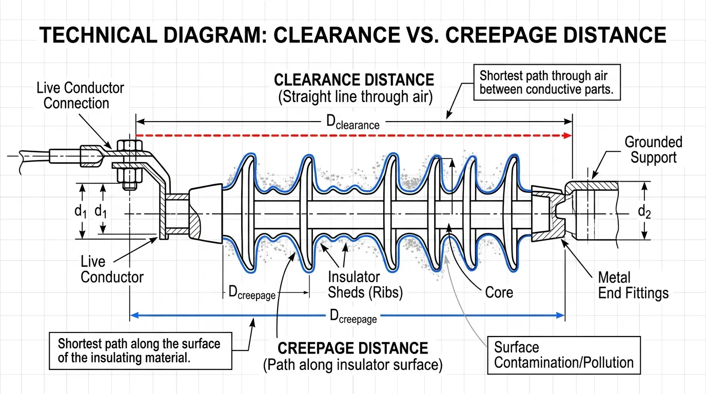
Creepage and clearance are the two fundamental spacing parameters in electrical insulation coordination. They protect against different failure modes, and confusing one for the other is one of the most common design errors.
| Parameter | Definition | Path Medium | Primary Hazard |
|---|---|---|---|
| Clearance | Shortest distance between two conductive parts through air | Air | Voltage flashover or spark discharge |
| Creepage distance | Shortest distance between two conductive parts along an insulating surface | Solid insulation surface | Surface tracking and leakage current |
Clearance is essentially air insulation. It protects against dielectric breakdown across a gap when the electric field strength exceeds the air’s withstand capability. The risk it addresses is flashover—a sudden, often dramatic arc through air.
Creepage distance addresses a slower but equally dangerous failure mode. When an insulating surface collects moisture, dust, salt deposits, or other conductive contamination, it can support small leakage currents across its surface. Over time, these micro-discharges erode the material and form carbonized tracks—a process called tracking. Once a conductive track is established, the insulation has permanently failed.
In most practical designs, creepage distance must be equal to or greater than clearance. This is because the surface path around, over, and along an insulating body is always at least as long as the straight-line air path—and often longer. Where environmental contamination is expected, the creepage requirement may be substantially larger than clearance to provide the necessary margin against surface degradation.
Why Creepage Distance Matters in Real-World Applications
Electrical products are not used in laboratory conditions. From the moment equipment is installed, it begins to face temperature cycling, humidity fluctuations, airborne dust, chemical vapors, condensation, and material aging. Each of these factors can reduce the effective insulation margin over the product’s service life.
The Tracking Failure Mechanism
When creepage distance is insufficient, the insulating surface between conductive parts becomes vulnerable to tracking—the progressive formation of a permanent conductive path along the material surface. The process typically follows a predictable sequence:
- Contaminants (moisture, dust, industrial residue) settle on the insulating surface.
- A thin conductive film forms, allowing small leakage currents to flow.
- Localized heating from leakage currents causes the moisture to evaporate unevenly, creating dry bands.
- Voltage across these dry bands causes small surface discharges (scintillations).
- Repeated discharges carbonize the insulating material, forming permanent conductive tracks.
- The tracks grow until insulation failure occurs—potentially causing arcing, fire, or electric shock.
This degradation mechanism is why creepage distance cannot be treated as a secondary consideration. It is not just about maintaining voltage withstand at the moment of installation. It is about maintaining insulation integrity over years of exposure to real operating conditions.
Products and Applications Where Creepage Distance Is Critical
Creepage distance requirements affect virtually every product that contains both conductive parts and insulating materials. However, the consequences of inadequate creepage are most severe in applications where contamination exposure is high or where failure consequences are serious:
- Low-voltage switchgear and distribution boards where terminal spacing, busbar supports, and device housings must maintain insulation under industrial pollution conditions
- Power supplies, converters, and transformers where primary-to-secondary isolation depends on both air gaps and surface paths across insulating barriers
- Terminal blocks and connection assemblies where multiple conductors at different potentials are mounted in close proximity
- Control panels and industrial automation enclosures that may be exposed to humidity, dust, or condensation
- Outdoor and pollution-exposed equipment including coastal, mining, or heavy industrial environments
- Molded insulating components such as busbar insulators, insulating partitions, and connector housings
For panel builders and equipment designers, creepage distance is not an abstract drawing annotation. It directly determines whether the final assembled product can maintain insulation integrity under the conditions it will actually face in service. Problems with insufficient creepage are often only discovered during testing or, worse, after field failures—as discussed in VIOX’s article on electrical panel mistakes before energization.
Main Factors That Determine Creepage Distance Requirements
Standards-based insulation design does not use a single fixed spacing rule. The minimum required creepage distance is determined by the interaction of several parameters, each of which reflects a different aspect of the electrical and environmental stress the insulation must withstand.
1. Working Voltage
The voltage across the insulation path is the most fundamental determinant of creepage distance. Higher working voltage drives greater surface leakage current and accelerates tracking under contaminated conditions, requiring proportionally greater surface distances.
The relevant voltage is the working voltage—the highest voltage that can occur across the insulation under normal operating conditions, excluding transients. For creepage distance determination, this is typically the RMS or DC value of the sustained voltage, not the peak transient value (which is more relevant to clearance).
As a general reference, IEC 62368-1 Table 28 requires minimum creepage distances ranging from approximately 0.6 mm at 50 V RMS to over 10 mm at 600 V RMS for reinforced insulation under pollution degree 2 conditions, depending on material group. These values increase further under pollution degree 3.
2. Insulation Type
The purpose of the insulation determines how conservative the spacing must be. IEC standards define several categories, and each carries different creepage requirements:
- Basic insulation provides the primary level of protection against electric shock under normal conditions. It is the minimum insulation that must be present.
- Supplementary insulation is an independent layer added as a backup in case basic insulation fails. It enables continued protection even after a single insulation fault.
- Double insulation combines basic and supplementary insulation into a system with two independent barriers. Products relying on double insulation typically do not require a protective earth connection.
- Reinforced insulation is a single insulation system designed to provide protection equivalent to double insulation. Because it relies on one barrier rather than two independent layers, its design margins are more conservative—typically requiring creepage distances approximately double those of basic insulation.
- Functional insulation is necessary for the equipment to operate correctly but is not relied upon alone for protection against electric shock.
This classification matters significantly in practice. A reinforced insulation path between primary and secondary circuits in a power supply may require twice the creepage distance of basic insulation at the same voltage level. Misidentifying the insulation type is one of the most common sources of non-compliant designs.
3. Material Group and Comparative Tracking Index (CTI)
The insulating material itself plays a direct role in determining how much creepage distance is required. Not all plastics, ceramics, or composite materials resist surface tracking equally well.
The Comparative Tracking Index (CTI) is a standardized measurement (per IEC 60112) that quantifies a material’s resistance to tracking. It represents the maximum voltage, in volts, at which the material can withstand 50 drops of ammonium chloride solution without forming a conductive track. A higher CTI indicates better tracking resistance.
Based on CTI values, insulating materials are classified into groups that directly affect creepage distance tables in product standards:
| Material Group | CTI Range (Volts) | Tracking Resistance | Creepage Impact |
|---|---|---|---|
| Group I | 600 ≤ CTI | Excellent | Shortest creepage for a given voltage |
| Group II | 400 ≤ CTI < 600 | Good | Moderate creepage requirements |
| Group IIIa | 175 ≤ CTI < 400 | Fair | Longer creepage required |
| Group IIIb | 100 ≤ CTI < 175 | Poor | Longest creepage required |
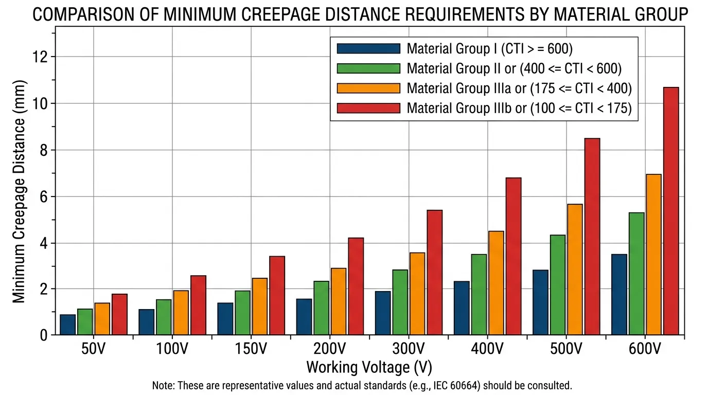
The practical difference is substantial. At the same working voltage, pollution degree, and insulation type, a Group IIIb material may require significantly more creepage distance than a Group I material. When the material group is unknown—which is surprisingly common in practice—the design must default to the most conservative assumption (Group IIIb), which can substantially increase required dimensions.
Selecting a higher-CTI material is one of the most effective ways to reduce creepage distance requirements without compromising safety, particularly in space-constrained designs like compact power supplies or high-density terminal assemblies.
4. Pollution Degree
Pollution degree is one of the most influential factors in creepage distance determination, yet it is also one of the most frequently underestimated. It classifies the micro-environment around the insulation—not the general cleanliness of the facility, but the actual conditions on the insulating surface.
| Pollution Degree | Environment Description | Typical Application |
|---|---|---|
| PD1 | No pollution occurs, or only dry non-conductive pollution that has no effect | Sealed enclosures, hermetically protected assemblies |
| PD2 | Only non-conductive pollution occurs, but occasional temporary conductivity caused by condensation is expected | Most indoor electrical equipment, control panels in clean industrial environments |
| PD3 | Conductive pollution occurs, or dry non-conductive pollution that becomes conductive due to expected condensation | Industrial equipment in factories, outdoor-adjacent installations, humid environments |
| PD4 | Continuous conductivity caused by conductive dust, rain, or wet conditions | Outdoor equipment fully exposed to weather |
Most indoor commercial and light industrial equipment is designed for pollution degree 2, which is the default assumption in many product standards. However, equipment installed in heavy industrial environments, food processing plants, agricultural buildings, or locations with significant airborne contamination may require design to pollution degree 3, which demands substantially greater creepage distances.
The difference between PD2 and PD3 can increase the required creepage distance by 50% or more at the same voltage level. Incorrectly assuming PD2 for an installation that actually experiences PD3 conditions is a common cause of premature insulation failure.
5. Overvoltage Category
Overvoltage category (OVC) describes the transient voltage stress that equipment may experience based on its position within the electrical installation. Equipment closer to the supply entrance faces higher transient exposure than equipment downstream of surge protection or behind transformers.
| Category | Position in Installation | Transient Exposure |
|---|---|---|
| OVC I | Protected circuits with limited transient voltage | Lowest |
| OVC II | Appliances connected to fixed wiring | Low to moderate |
| OVC III | Fixed installation equipment, distribution boards | Moderate to high |
| OVC IV | Origin of installation, utility connection | Highest |
Overvoltage category primarily affects clearance requirements (since transients are short-duration, high-voltage events that stress air gaps), but it also influences the overall insulation coordination strategy. In product standards such as IEC 62368-1 and IEC 60664-1, the overvoltage category is used together with the supply voltage to determine the required impulse withstand voltage, which in turn sets the minimum clearance.
6. Altitude
Standard creepage and clearance values in IEC standards are based on a reference altitude of 2,000 meters above sea level (in IEC 62368-1 and related standards). At higher altitudes, the reduced air density decreases the dielectric strength of air gaps.
This directly affects clearance requirements—clearance values must be multiplied by a correction factor at altitudes above the reference. For example, at 3,000 meters, the correction factor per IEC 60664-1 Annex A is approximately 1.14, meaning clearances must increase by about 14%.
While altitude correction primarily applies to clearance (air insulation), it indirectly affects creepage evaluation because the overall insulation coordination must remain consistent. In a design where clearance and creepage are close to the same value, an altitude correction to clearance may also necessitate revisiting the creepage path to ensure the surface distance is not the weak link.
7. Humidity, Dust, and Condensation
Beyond the formal pollution degree classification, real-world environmental conditions can create surface contamination scenarios that stress insulation in ways that standard tables alone do not fully capture.
Specific conditions that demand careful attention to creepage distance include:
- Coastal environments where airborne salt deposits create conductive films on insulating surfaces
- Industrial facilities with oil mist, metallic dust, carbon dust, or chemical vapors
- Agricultural and food processing environments with high humidity and organic contamination
- Installations subject to regular condensation cycles due to temperature differentials between equipment and ambient air
- Locations with high altitude combined with high humidity, where both clearance and creepage margins are stressed simultaneously
In these environments, conservative creepage distance design, combined with appropriate material selection and surface treatment (such as conformal coating on PCBs), provides the most reliable long-term insulation performance.
How to Measure Creepage Distance
Correct creepage distance measurement is essential for both design verification and production quality control. The fundamental principle is straightforward: measure the shortest path along the insulating surface between two conductive parts. However, the practical application requires care and attention to detail.
Step 1: Identify the Conductive Reference Points
Begin by clearly identifying the two conductive parts between which creepage distance must be maintained. Common measurement pairs include:
- Adjacent terminals at different potentials
- Live parts to accessible grounded metal (enclosure, heatsink, mounting hardware)
- Primary circuit to secondary circuit across an isolation barrier
- Line conductor to neutral, or line conductor to protective earth
- Busbar to busbar, or busbar to grounded support structure
Each pair represents a different insulation boundary with potentially different voltage, insulation type, and therefore different creepage requirements.
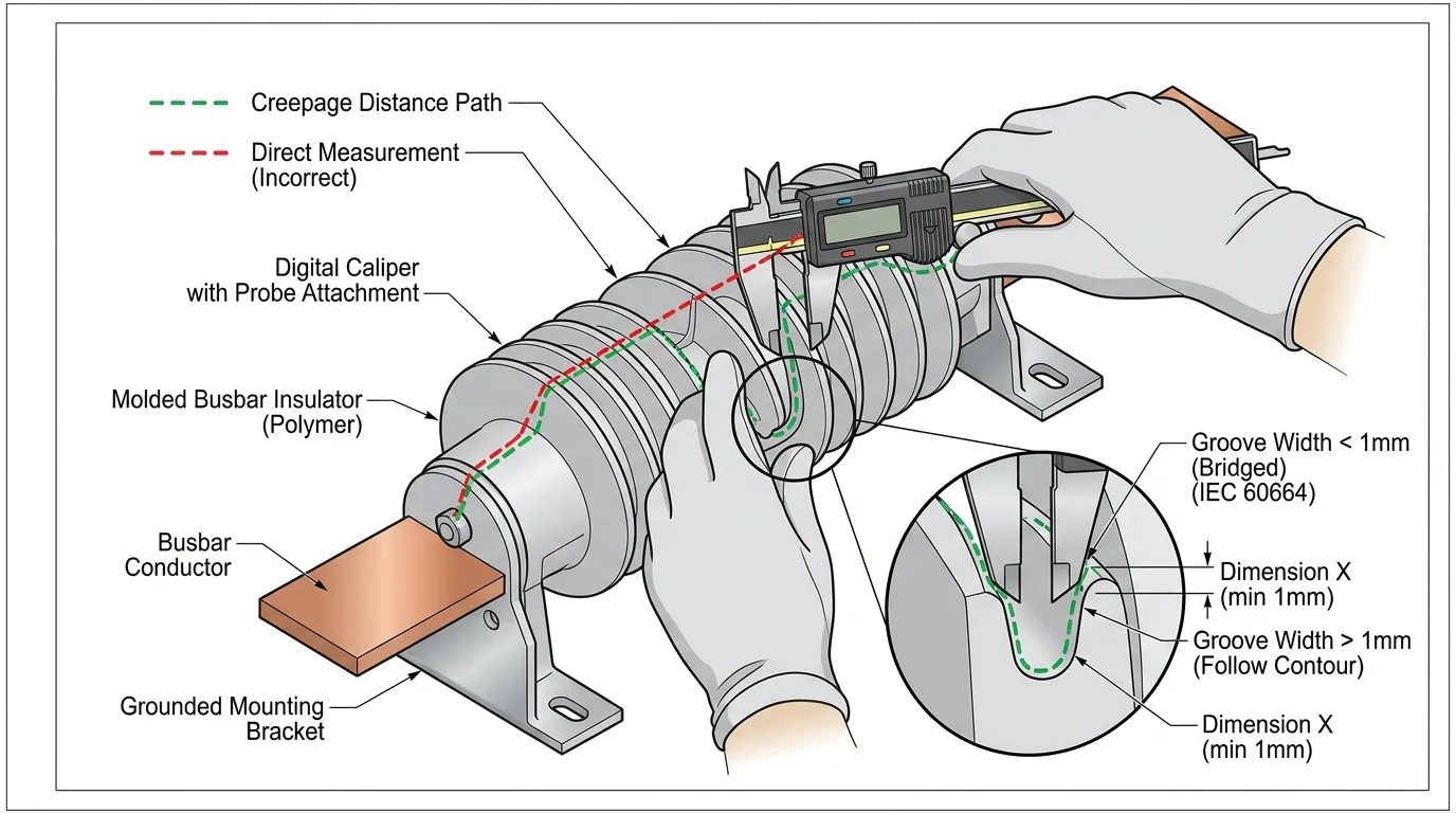
Step 2: Trace the Insulating Surface Path
Creepage distance follows the physical surface of the insulating material. This means following every contour, groove, rib, slot, and molded feature of the insulation body between the two conductive reference points.
Do not measure in a straight line through air—that would be clearance. For creepage, the measurement path must remain on the surface of the insulating material at all times, including around barriers, along molded channels, and over any surface features.
Step 3: Account for Grooves, Ribs, and Barriers
Insulating components are often designed with ribs, slots, or barriers specifically to increase the creepage path length. When measuring, these features contribute to the total creepage distance only if they meet certain dimensional criteria defined in the applicable standard.
For example, under IEC 62368-1 and IEC 60664-1, a groove or rib must have a minimum width (typically 1 mm or more, depending on the pollution degree) to count toward the creepage path. Grooves narrower than this minimum are “bridged” in the measurement—meaning the path is taken across the top of the groove as if it were not there, because contamination can easily span narrow gaps.
This distinction is critical. An insulation designer who relies on narrow decorative ribs to meet creepage requirements may find that the ribs do not count under the measurement rules of the applicable standard.
Step 4: Select the Appropriate Measurement Method
Depending on the geometry and the stage of the design/production process, different measurement approaches may be appropriate:
- Calipers and feeler gauges for simple, accessible profiles on physical samples
- Flexible measuring tape or thread for curved surfaces where the contour must be followed precisely
- CAD contour measurement tools for design-stage verification using 3D models or 2D cross-sections
- Optical measurement systems for precision verification in production quality control
- Inspection templates or fixtures for repeated checks during production runs
For complex geometries—such as molded connector housings or busbar support insulators—it is often helpful to identify the critical creepage path in the 3D model first, then verify the physical dimension on prototypes or production samples.
Step 5: Find the Shortest Surface Path
The required measurement is the minimum surface path between the conductive parts. In a complex 3D geometry, there may be multiple possible paths along different surfaces, around different features, or through different sections of the insulating body. The correct creepage distance is the shortest of all these paths.
This is where measurement errors most commonly occur. Engineers may measure a convenient or obvious path and miss a shorter path around another edge or through a gap that they did not initially consider.
Step 6: Verify Against Manufacturing Tolerances
For molded or assembled insulating parts, the nominal design dimension may differ from the actual production dimension. Manufacturing tolerances, parting-line flash, sink marks, warpage, and assembly variation can all reduce the effective creepage distance.
Measurement should be performed on multiple samples to account for this variation. The worst-case (minimum) measured value is the one that must meet the creepage requirement, not the average.
Step 7: Compare to the Applicable Standard Requirement
The measured creepage distance is only meaningful when evaluated against the specific requirement for that insulation boundary. The required minimum depends on the combination of:
- Working voltage across the insulation
- Type of insulation (basic, supplementary, reinforced, functional)
- Material group of the insulating surface
- Pollution degree of the operating environment
- Applicable product standard and its specific tables
A creepage distance of 6 mm might be more than adequate for one application and dangerously insufficient for another, depending on these parameters.
Practical Example: Panel Builder Creepage Evaluation
Consider a low-voltage distribution panel rated for 400 V AC, installed in a light industrial environment classified as pollution degree 2. The panel contains molded insulating terminal blocks, busbar support insulators, and device mounting plates.
During design review, the engineer measures the clearance between adjacent busbars at different phases and finds 12 mm of air gap—comfortably exceeding the clearance requirement. However, the creepage path along the surface of the busbar support insulator between the same two phases measures only 8 mm.
If the insulating material is a Group IIIa thermoplastic (CTI between 175 and 400), the minimum creepage distance for 400 V reinforced insulation under PD2 per IEC 62368-1 could be approximately 8.0 mm or more, depending on the specific standard table. The design is marginal.
Now consider that this same panel may be installed in an environment that actually experiences pollution degree 3 conditions—perhaps near a loading dock where moisture and dust enter the enclosure. Under PD3 conditions, the required creepage distance increases substantially, and the 8 mm surface path is no longer adequate.
This example illustrates two important principles:
- Clearance compliance alone does not guarantee creepage compliance. The air gap can be generous while the surface path is insufficient.
- The assumed pollution degree must match the actual installation environment. A panel designed for PD2 that ends up in PD3 conditions faces a real insulation risk.
For panel builders, this same evaluation logic applies to terminal spacing, molded component supports, control-device housings, and enclosure-mounted insulated assemblies. When selecting busbar insulators for distribution panels, verifying both the material CTI rating and the actual surface path dimensions against the installation’s pollution degree is essential. VIOX’s guide on top 5 mistakes to avoid when installing MCB busbars covers related spacing issues that arise specifically during panel integration.
Common Design and Inspection Mistakes
Treating Clearance and Creepage as Interchangeable
This remains the most frequent error. Clearance is through air; creepage is along the surface. They protect against different failure modes, are governed by different tables in the standards, and are affected by different parameters. A design review that checks only one will miss real insulation risk from the other.
Underestimating the Pollution Degree
Designers often default to pollution degree 2 because it is the most common assumption in product standards. But the actual micro-environment around the insulation may be worse than PD2. Industrial panels near water, steam, machining operations, or open loading areas may realistically face PD3 conditions. Choosing the wrong pollution degree can invalidate the entire creepage calculation.
Assuming All Insulating Plastics Are Equivalent
A polyamide (PA66) housing, a polycarbonate (PC) barrier, and a PBT insulating plate may look similar on a drawing, but their CTI values can differ by hundreds of volts. Using a Group IIIb material in a location where the design was calculated for Group I can leave the creepage distance seriously inadequate. Always verify the material group before finalizing the design.
Relying on Narrow Ribs or Features That Do Not Count
As discussed in the measurement section, grooves, ribs, and slots must meet minimum dimensional criteria to count toward the creepage path. A molded rib that is only 0.5 mm wide may look like it adds 3 mm of surface path, but under the measurement rules of IEC 60664-1, it may be bridged entirely and contribute nothing to the creepage distance.
Forgetting Altitude Corrections for Clearance
While altitude primarily affects clearance rather than creepage, overlooking the altitude correction can create a cascading problem. If the altitude-corrected clearance exceeds the designed creepage, then the creepage path—not the air gap—becomes the weak point in the insulation system.
Measuring the Wrong Path
The correct creepage distance is the shortest surface path, not the most obvious or most convenient path to measure. In complex 3D geometries, the shortest path may follow an unexpected route around a corner, through a gap, or along a surface that is not immediately visible. Always consider multiple possible paths and identify the minimum.
Missing Spacing Problems During Panel Assembly
A component may be fully compliant with creepage requirements when evaluated on its own datasheet. But when that component is installed in a panel—next to other devices, wiring, metal structures, or mounting hardware—the effective creepage paths may be reduced by proximity to other conductive parts that were not present during the component-level evaluation. This is a system-level integration issue that requires attention during panel design review and final inspection.
Relevant Standards for Creepage Distance
The specific creepage distance requirement depends on the product family and the applicable safety standard. No single universal spacing rule applies to all equipment. Key standards that address creepage and clearance include:
- IEC 60664-1 – Insulation coordination for equipment within low-voltage supply systems. This is the foundational standard for creepage and clearance methodology. It defines the material groups, pollution degrees, and measurement rules that most product standards reference.
- IEC 62368-1 – Audio/video, information and communication technology equipment – Safety requirements. Widely used for power supplies, IT equipment, telecommunications gear, and consumer electronics. Contains detailed tables for creepage and clearance based on working voltage, pollution degree, and material group.
- IEC 60947-1 – Low-voltage switchgear and controlgear – General rules. The primary reference for industrial switchgear, contactors, circuit breakers, and related equipment.
- IEC 61010-1 – Safety requirements for electrical equipment for measurement, control, and laboratory use. Applies to test and measurement instruments, laboratory equipment, and industrial control devices.
- IEC 60815 series – Selection and dimensioning of high-voltage insulators intended for use in polluted conditions. While focused on high-voltage outdoor insulators, the pollution classification and specific creepage distance concepts from this standard inform thinking about pollution effects at all voltage levels.
- IEC 60112 – Method for the determination of the proof and the comparative tracking indices of solid insulating materials. Defines the CTI test method used to classify materials into groups.
The design process should always begin by identifying the correct product standard for the equipment category. Creepage requirements from one standard cannot be blindly applied to a product governed by a different standard, because the underlying assumptions about voltage classification, pollution conditions, and safety margins may differ.
How to Extend Creepage Distance in Space-Constrained Designs
When physical space is limited but creepage distance requirements must be met, engineers have several proven techniques available:
Add molded ribs or barriers to the insulating surface. A properly dimensioned rib (meeting the minimum width requirements of the applicable standard) forces the surface leakage path to travel up one side and down the other, effectively adding twice the rib height to the creepage distance without increasing the overall footprint. High-quality busbar insulators often incorporate optimized rib designs specifically to maximize creepage distance in compact panel layouts.
Select a higher-CTI material. Moving from a Group IIIa to a Group I material can significantly reduce the minimum required creepage distance at the same voltage and pollution degree.
Apply conformal coating or potting to insulating surfaces. While coating does not change the measured creepage distance on the base material, it can effectively change the pollution degree at the insulating surface (from PD2 or PD3 to PD1 in some cases), which can substantially reduce the required creepage distance.
Redesign the insulating geometry to route the creepage path more efficiently. Sometimes a small change in the shape of a molded housing—adding a channel, relocating a mounting boss, or adjusting parting line placement—can add several millimeters of surface path without affecting the overall dimensions.
Use sealed or enclosed construction to reduce the pollution degree classification. If the insulation can be protected from external contamination—through gasketed enclosures, potting, or conformal coating—the applicable pollution degree may be reduced, allowing shorter creepage distances.
Conclusion
Creepage distance is the shortest path between two conductive parts measured along the surface of solid insulation. It is fundamentally different from clearance, and both must be independently evaluated to achieve a safe, standards-compliant electrical design.
The required creepage distance is not a single fixed number. It is determined by the interaction of working voltage, insulation type, material group (CTI), pollution degree, overvoltage category, and the real operating environment. Getting any one of these inputs wrong can result in a design that passes a desk review but fails in service.
For engineers and panel builders, correct creepage distance design requires understanding the measurement rules, selecting appropriate materials, honestly assessing the installation environment, and verifying the final product against the applicable standard. It is not just a geometric detail on a drawing. It is a core element of insulation reliability and electrical safety.
FAQ
What is creepage distance?
Creepage distance is the shortest distance between two conductive parts measured along the surface of an insulating material. It represents the path that surface leakage current would follow under contaminated conditions, and it is a fundamental parameter in electrical insulation design and safety evaluation.
What is the difference between creepage distance and clearance?
Clearance is the shortest distance through air between two conductive parts—it protects against voltage flashover. Creepage distance is the shortest distance along the insulating surface between those same parts—it protects against surface tracking and leakage current. Both must be evaluated independently because they address different failure mechanisms.
Why is creepage distance important?
Creepage distance prevents surface leakage and tracking failure, especially in environments with humidity, dust, condensation, or conductive contamination. When the insulating surface between conductive parts becomes contaminated, it can support leakage currents that progressively carbonize the material, eventually creating a permanent conductive path and causing insulation failure.
How do you measure creepage distance?
Measure the shortest path along the insulating surface between two conductive parts, following every contour, groove, rib, and barrier of the insulating body. Do not measure through air (that would be clearance). Account for the dimensional rules in the applicable standard regarding minimum groove widths and barrier heights that qualify as part of the creepage path.
Is creepage distance always larger than clearance?
In most practical designs, yes. The surface path around and along an insulating body is typically longer than the straight-line air path between the same two points. Standards generally require creepage distance to be at least equal to clearance, and in contaminated environments, the creepage requirement is often substantially larger.
What factors determine minimum creepage distance?
The primary factors are working voltage, insulation type (basic, supplementary, reinforced, or functional), material group (based on CTI), pollution degree of the operating environment, and the applicable product standard. Secondary factors include overvoltage category, altitude, and specific environmental conditions such as humidity or chemical exposure.
What is CTI and why does it matter for creepage distance?
CTI stands for Comparative Tracking Index, measured per IEC 60112. It quantifies an insulating material’s resistance to surface tracking in volts. Higher CTI values indicate better tracking resistance. Materials are classified into groups (I, II, IIIa, IIIb) based on CTI, and these groups directly affect the minimum creepage distance required by product safety standards. A Group I material (CTI ≥ 600 V) may require significantly less creepage distance than a Group IIIb material (CTI 100–175 V) at the same voltage and pollution degree.
Does altitude affect creepage distance?
Altitude primarily affects clearance because reduced air density at higher elevations decreases the dielectric strength of air gaps. Standard clearance values typically apply up to 2,000 m altitude, with correction factors required above that. While creepage distance tables are not directly altitude-dependent, the overall insulation coordination must remain consistent, so altitude can indirectly affect creepage evaluation.
Which standards define creepage distance requirements?
The applicable standard depends on the product category. IEC 60664-1 provides the foundational methodology for insulation coordination in low-voltage systems. IEC 62368-1 is widely used for IT, audio/video, and power conversion equipment. IEC 60947-1 covers low-voltage switchgear. IEC 61010-1 applies to measurement, control, and laboratory equipment. IEC 60815 addresses insulation in polluted outdoor environments. The design should always start from the correct standard for the specific product type.
How can I reduce creepage distance requirements in a compact design?
The most effective approaches include selecting a higher-CTI insulating material (moving to a better material group), adding molded ribs or barriers to extend the surface path, applying conformal coating to reduce the effective pollution degree at the insulating surface, or using sealed construction to qualify for a lower pollution degree classification. Each approach must be validated against the specific requirements of the applicable standard.
