
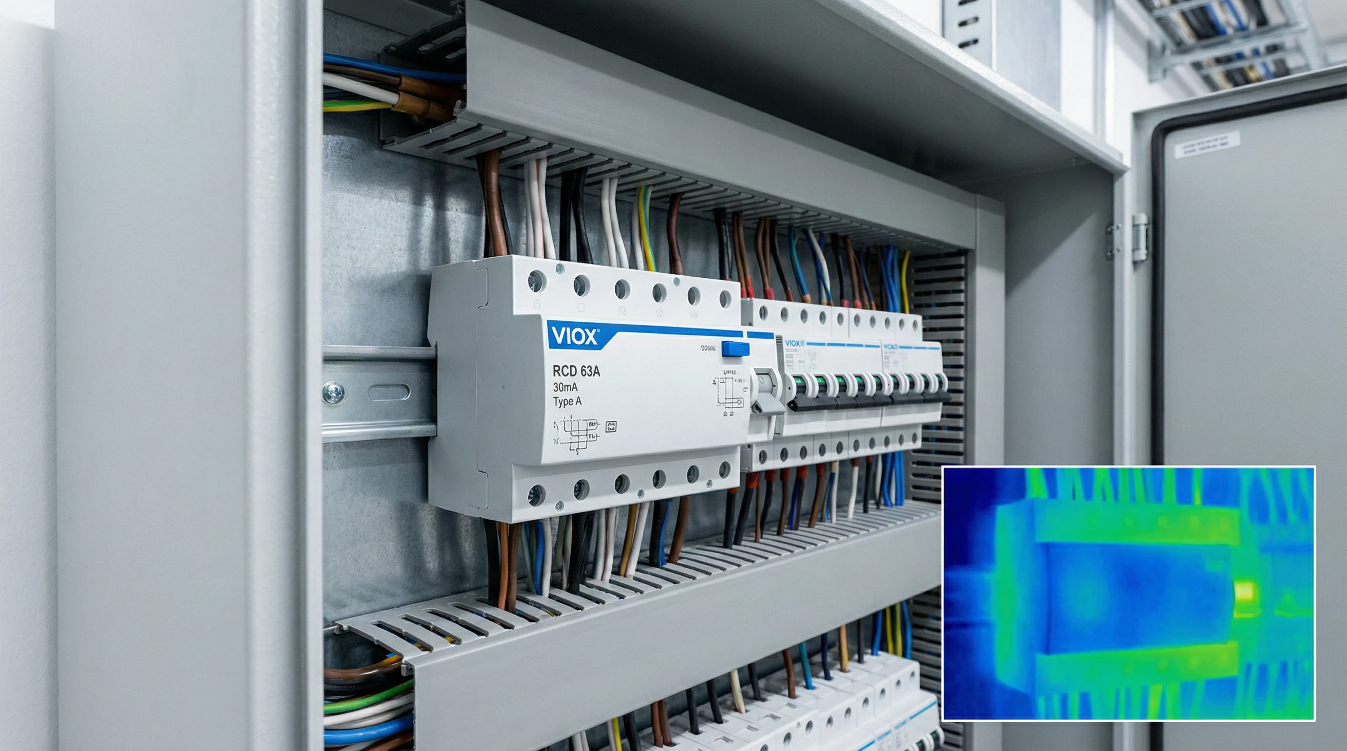
A contractor walks into a facility manager’s office. “The RCD keeps tripping in the server room,” the manager says. “We’ve checked everything. No insulation faults. But it still trips twice a week.”
The contractor swaps the 40A RCD for a 63A unit. Same 30mA trip threshold—just higher amperage. Two weeks later: no trips. Problem vanished.
But why? The residual operating current (IΔn) didn’t change. So why does upgrading the rated load current (In) from 40A to 63A sometimes stop nuisance tripping?
If you’ve spent years in the field, you know this “fix” works often enough to be more than coincidence. The answer lies in an overlooked factor: thermal stability and installation sensitivity under heavy load.
This guide explains why the 40A-to-63A swap sometimes works, why it’s treating a symptom rather than the disease, and what the proper diagnostic solutions look like.
The Theory vs. The Field: Understanding In and IΔn
When electricians debate the 40A-to-63A swap on forums like Mike Holt or Australian electrician communities, the theorists are quick to point out the logical flaw. They insist you must distinguish two completely separate parameters:
In (Rated Load Current): 40A or 63A. This defines how much current the RCD’s copper contacts, busbars, and internal conductors can carry continuously without overheating or degrading. It’s a thermal and mechanical rating.
IΔn (Rated Residual Operating Current): Typically 30mA. This defines the earth leakage current threshold that will cause the device to trip. It’s an electrical sensitivity rating.
From pure theory, changing In should have zero effect on IΔn. Upgrading to 63A doesn’t raise the 30mA leakage threshold. If an appliance is genuinely leaking 35mA to ground, both the 40A and 63A versions should trip. The swap makes no sense—like replacing your car’s engine to fix a flat tire.
Table 1: Parameter Comparison – 40A vs 63A RCD (Both 30mA IΔn)
| Parameter | 40A RCD | 63A RCD | What Changes? |
|---|---|---|---|
| Rated Load Current (In) | 40A | 63A | ✅ Contacts/busbar capacity increases |
| Rated Residual Operating Current (IΔn) | 30mA | 30mA | ❌ Unchanged – still trips at 30mA leakage |
| Trip Threshold per IEC 61008 | 15-30mA | 15-30mA | ❌ Same operating window |
| Maximum Continuous Load Capacity | 40A | 63A | ✅ Higher sustained current capability |
| Protection Against Earth Leakage | 30mA | 30mA | ❌ Identical protection level |
So if IΔn stays at 30mA, why does the swap sometimes stop nuisance tripping? The theory is correct—but incomplete. Real-world RCDs don’t operate in textbook conditions.
Why the 63A Swap Sometimes Works: The Hidden Role of Heat and Installation Geometry
The field electricians are right—the swap does work, but not for the reason most assume. The real mechanism involves thermal stability and installation-induced sensitivity that textbook theory ignores.
The Toroidal Transformer and Its Vulnerabilities
Inside every RCD sits a toroidal current transformer that monitors phase and neutral conductors. In perfect conditions, current flowing out equals current returning, creating opposing magnetic fields that cancel. Any imbalance—leakage to ground—triggers the trip mechanism.
But perfect conditions rarely exist. Two factors introduce unwanted sensitivity:
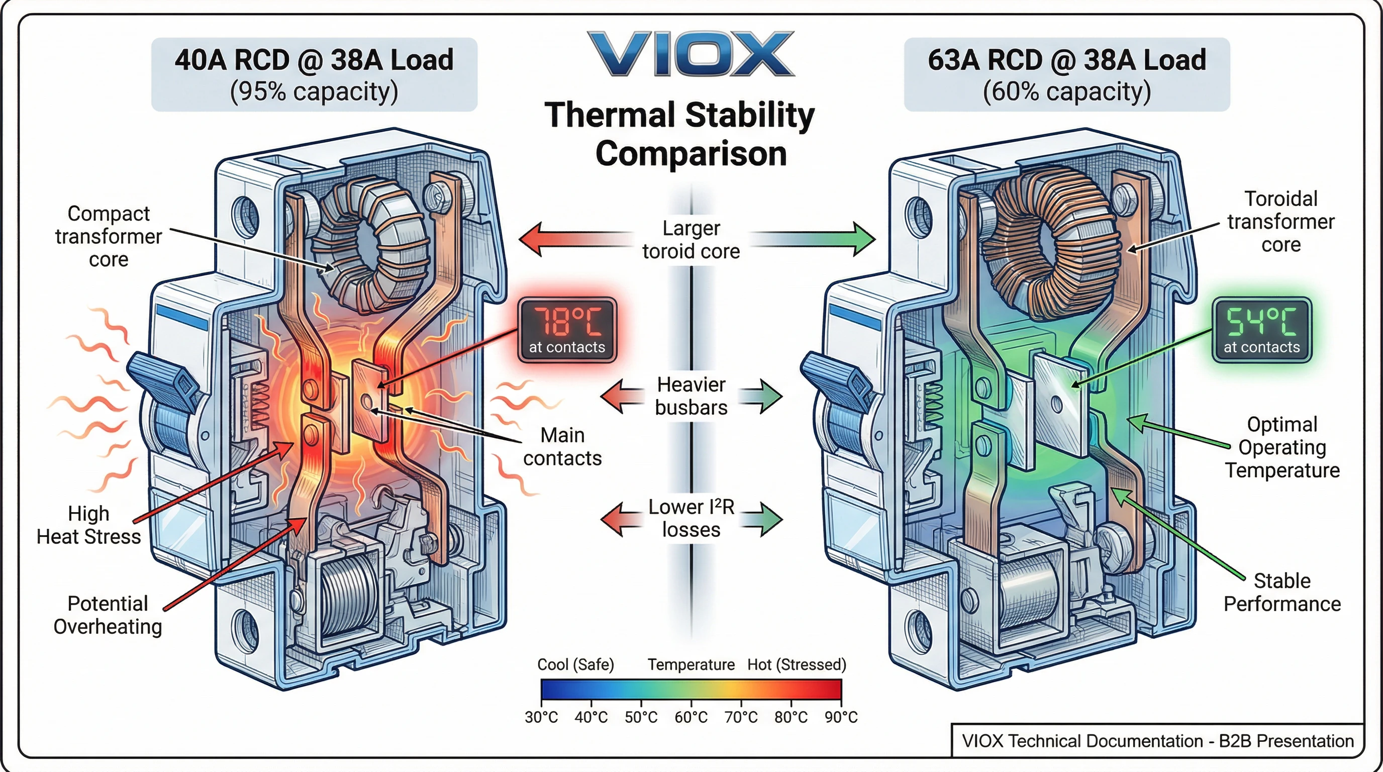
1. High Load Current Effects: When a 40A RCD operates near capacity (38A continuous), substantial heat affects the toroid’s magnetic core and trip mechanism stability. High currents can create field imbalances if conductors aren’t perfectly centered or if nearby ferrous metal distorts geometry.
2. Installation Geometry: Conductors not centered through the toroid, nearby ferrous enclosures, or cable routing asymmetries can cause phantom imbalances. These effects worsen under high load.
Why Larger Frames Reduce Sensitivity
Upgrading to 63A provides:
- Larger magnetic circuit: Bigger toroidal cores are less sensitive to installation imperfections and conductor positioning errors.
- Lower internal losses: Heavier busbars and larger contacts mean lower resistance. At the same 38A load, the 63A device runs cooler—reducing thermal drift.
- Better thermal margin: A 63A device at 38A operates at 60% capacity with stable temperatures. The 40A device at 38A (95% capacity) is thermally maxed out.
The Real Culprit: Accumulated Background Leakage
While thermal effects explain why the 63A swap occasionally helps, they’re not the root cause of most nuisance tripping. The real problem is cumulative background leakage—and upgrading amperage does nothing to address it.
The Modern Electronic Load Challenge
Modern installations are filled with switch-mode power supplies: computers, LED lighting, variable frequency drives, smart appliances. Each contains EMI filter capacitors that leak tiny currents to ground during normal operation.
Typical leakage: Desktop computer (1-1.5mA), LED driver (0.5-1mA), VFD (2-3.5mA), laptop charger (0.5mA).
These aren’t faults—they’re compliant leakage permitted by safety standards. But on a single RCD protecting multiple circuits, they accumulate.
The Arithmetic of Disaster
Consider a typical small office protected by one 40A RCD covering three circuits:
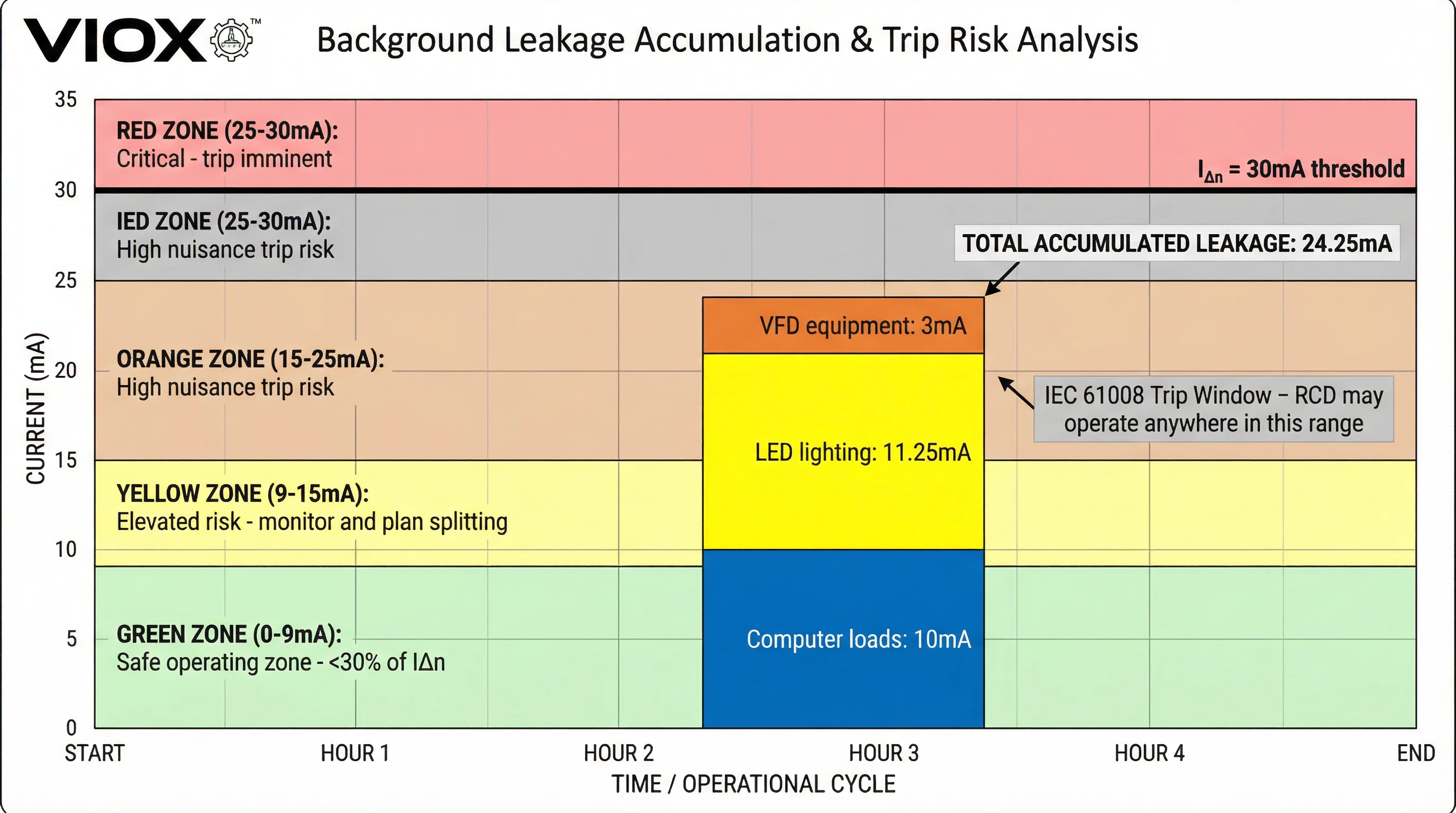
- Circuit 1 (Lighting): 15 LED fixtures × 0.75mA = 11.25mA
- Circuit 2 (Workstations): 8 computers × 1.25mA = 10mA
- Circuit 3 (HVAC): 1 VFD unit × 3mA = 3mA
Total standing leakage: 24.25mA
Now here’s the critical part: IEC 61008 permits RCDs to trip anywhere between 50% and 100% of IΔn. For a 30mA device, that means the trip threshold can be as low as 15mA or as high as 30mA depending on the specific device and operating conditions.
Your installation is already sitting at 24.25mA. Any transient—a computer power supply switching on, an inrush from a motor start, a minor voltage surge—can push the instantaneous leakage above 30mA and cause a trip. The RCD is doing exactly what it’s designed to do. There’s no fault. The architecture is simply overloaded.
Table 2: Background Leakage Accumulation Example
| Circuit | Load Type | Quantity | Leakage per Device | Total Circuit Leakage |
|---|---|---|---|---|
| Lighting | LED fixtures | 15 | 0.75mA | 11.25mA |
| Workstations | Desktop PCs | 8 | 1.25mA | 10.0mA |
| HVAC | VFD controller | 1 | 3.0mA | 3.0mA |
| Total on Single RCD | — | — | — | 24.25mA |
| 30mA RCD Trip Window | — | — | — | 15-30mA |
| Risk Level | — | — | — | HIGH – Already 81% of IΔn |
Industry Guidance: The 30% Rule
Manufacturers and standards bodies recommend keeping standing leakage below 30% of IΔn to avoid nuisance tripping. For a 30mA RCD, that means limiting background leakage to approximately 9mA per device. The example above exceeds this guideline by nearly 3x.
Swapping to a 63A RCD doesn’t change the math. The leakage is still 24.25mA, and the trip threshold is still 30mA. You haven’t fixed anything—you’ve just gotten lucky if trips stop, probably because the new device happens to have a trip characteristic closer to 30mA than 15mA.
The Proper Fix: Distributed Protection with RCBOs
If upgrading amperage is treating the symptom, what’s the cure? The answer is architectural: migrate from centralized RCD protection to distributed RCBO (Residual Current Breaker with Overcurrent protection) protection.
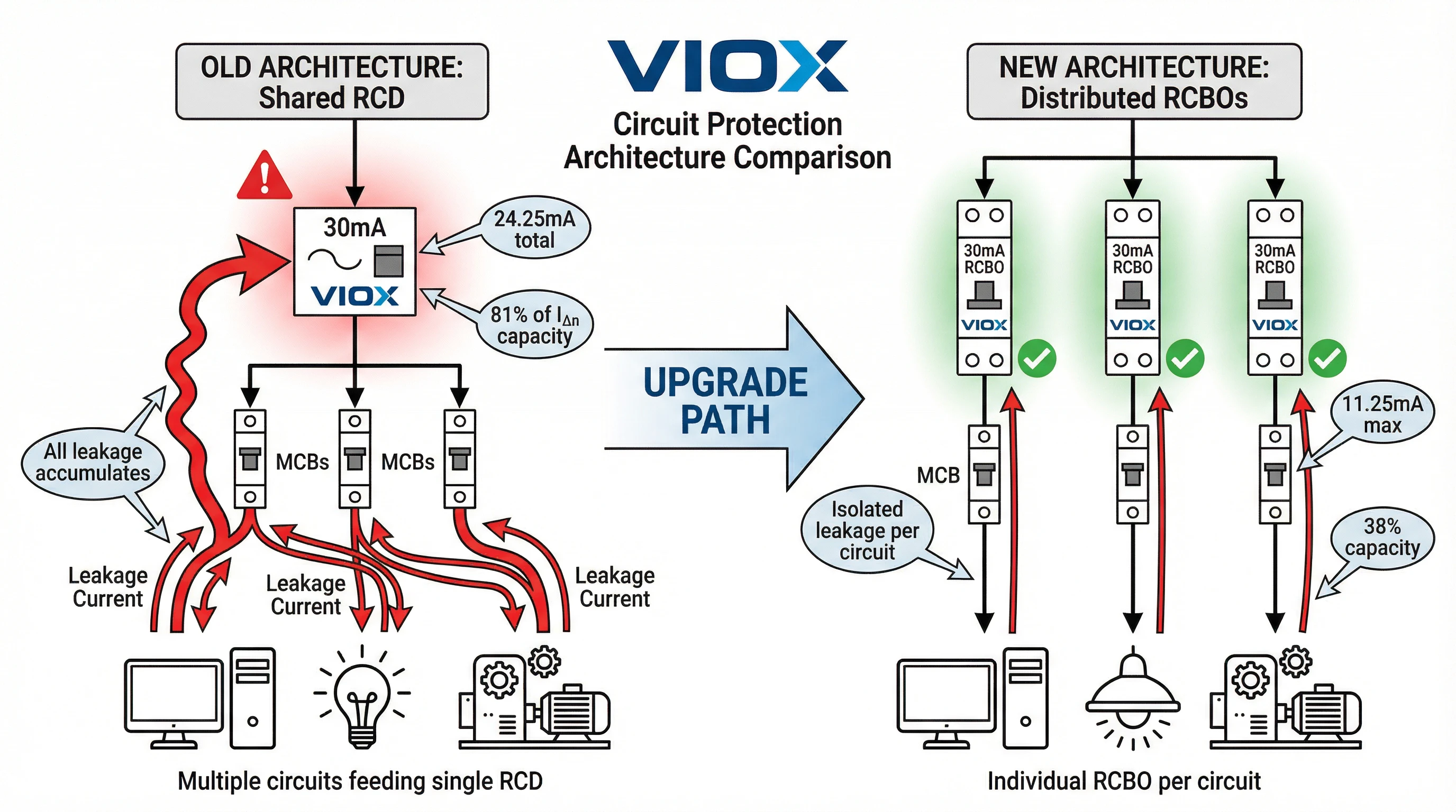
The Old Architecture: One RCD, Multiple Circuits
Traditional panels use a single RCD upstream of multiple MCBs. One 40A or 63A RCD protects 3-5 circuits. This “shared protection” model worked when loads were simple resistive heaters with negligible leakage.
But modern installations create a bottleneck. All background leakage funnels through one 30mA window.
The New Architecture: One RCBO Per Circuit
RCBOs combine overcurrent protection (MCB function) and residual current protection (RCD function) in a single device. Instead of one shared RCD, each circuit gets its own 30mA leakage budget.
Using the earlier office example:
- 1 RCD (30mA) protecting 3 circuits
- Total leakage: 24.25mA
- Utilization: 81% of capacity
- Result: Frequent nuisance trips
New design:
- 3 RCBOs (each 30mA)
- Circuit 1 leakage: 11.25mA (38% of capacity)
- Circuit 2 leakage: 10mA (33% of capacity)
- Circuit 3 leakage: 3mA (10% of capacity)
- Result: Each circuit operates well within safe margins
Additional Benefits
Fault localization: Only the affected circuit goes offline, not the entire room. Downtime drops dramatically.
Faster troubleshooting: You immediately know which circuit has the problem.
Scalability: Each new RCBO brings its own 30mA budget.
Compliance: Many regions now require RCBO protection for specific circuits.
Table 3: Shared RCD vs Distributed RCBO Architecture
| Characteristic | Shared RCD + MCBs | Distributed RCBOs |
|---|---|---|
| Leakage Budget | All circuits share 30mA | Each circuit has 30mA |
| Nuisance Trip Risk | High (cumulative leakage) | Low (isolated leakage) |
| Fault Impact | All protected circuits trip | Only faulty circuit trips |
| Troubleshooting Time | Long (test each circuit) | Short (fault is localized) |
| Installation Cost | Lower upfront | Higher upfront |
| Operational Cost | Higher (frequent callouts) | Lower (fewer nuisance trips) |
| Compliance with 30% Rule | Difficult with >3 circuits | Easy for any circuit count |
| Future Expansion | Worsens leakage problem | No impact on existing circuits |
Diagnostic Methodology: Be a Troubleshooter, Not a Parts-Swapper
When faced with RCD nuisance tripping, follow a systematic diagnostic process before reaching for tools or ordering replacement devices.
Step 1: Measure Standing Earth Leakage
Use a clamp-on leakage current meter:
- At the RCD: Clamp around the earth conductor downstream. This measures total leakage from all protected circuits.
- Per circuit: Clamp around phase and neutral together for each branch.
- < 9mA: Acceptable
- 9-15mA: Monitor, plan to split circuits
- 15-25mA: High nuisance trip risk
- > 25mA: Immediate architectural change needed
Step 2: Verify RCD Type
Modern electronic loads produce pulsating DC leakage that Type AC RCDs cannot detect properly.
Type AC: Legacy. Detects only pure sinusoidal AC leakage. Obsolete. Prohibited in Australia since 2023.
Type A: Detects AC and pulsating DC leakage. Minimum standard for modern installations.
Type B/F: Required for high DC leakage (EV chargers, solar inverters, industrial VFDs).
If your RCD says “Type AC,” replacement with Type A is mandatory regardless of amperage.
Step 3: Inspect Installation Quality
- Conductor centering: Ensure phase and neutral pass through the center of the toroidal opening, not pressed against one side.
- Ferrous clearance: Keep steel enclosures, conduit fittings, and mounting hardware at least 50mm from the RCD toroid.
- Load balance: Verify the RCD isn’t operating continuously above 80% of its rated current.
Step 4: Plan Architectural Changes
Based on measurements:
- If leakage < 9mA: Problem may be thermal or installation-related. Consider 63A upgrade with geometry corrections.
- If leakage 9-25mA: Circuit splitting needed. Migrate high-leakage circuits (IT, VFD, LED) to dedicated RCBOs.
- If leakage > 25mA: Full RCBO conversion. Shared RCD architecture is no longer viable.
Table 4: Troubleshooting Decision Matrix
| Measured Standing Leakage | Load Current vs In | RCD Type | Recommended Action |
|---|---|---|---|
| < 9mA | < 70% rated | Type A | Check installation geometry; monitor |
| < 9mA | > 80% rated | Type A | Upgrade to 63A frame for thermal margin |
| < 9mA | Any | Type AC | Replace with Type A immediately |
| 9-15mA | Any | Type A | Split highest-leakage circuit to RCBO |
| 15-25mA | Any | Type A | Migrate 2-3 circuits to RCBOs |
| > 25mA | Any | Any | Full RCBO conversion required |
Frequently Asked Questions
Q: Will upgrading from 40A to 63A RCD stop nuisance tripping?
A: Sometimes, but not for the reason most people think. The upgrade doesn’t change the 30mA leakage threshold (IΔn). It can help if your problem stems from thermal instability or installation sensitivity under high load current—the larger 63A frame runs cooler and has a less sensitive magnetic circuit. But if the root cause is accumulated background leakage from electronic devices, the 63A swap won’t fix anything. Measure your standing leakage first.
Q: How do I measure background earth leakage?
A: Use a clamp-on leakage current meter around the earth conductor downstream of the RCD or around phase and neutral wires together for individual circuits. If total leakage exceeds 9mA on a 30mA RCD, you’re at high risk for nuisance trips.
Q: What’s the difference between Type AC and Type A RCDs?
A: Type AC detects only pure sinusoidal AC leakage. It’s obsolete for modern installations because electronic loads produce pulsating DC leakage that Type AC can’t handle reliably. Type A detects both AC and pulsating DC leakage, making it suitable for installations with switch-mode power supplies. Australia banned new Type AC installations in 2023.
Q: What’s the “30% rule” for RCD leakage?
A: Industry guidance recommends keeping standing leakage below 30% of the RCD’s rated trip current (IΔn) to avoid nuisance trips. For a 30mA RCD, that means limiting background leakage to about 9mA, leaving headroom for transient inrush currents.
Q: Should I upgrade to RCBOs or just keep using RCDs?
A: If your measured background leakage exceeds 9mA, RCBOs are the proper solution. Each circuit gets its own 30mA leakage budget, preventing accumulation. RCBOs also localize faults—only the problem circuit trips. The upfront cost is typically recovered within 1-2 years through reduced callouts and downtime.
Protect Your Installation with the Right Strategy
The 40A-to-63A RCD swap is a field fix that occasionally works—not because it increases leakage tolerance, but because larger frames reduce thermal and installation-induced sensitivity. It’s treating symptoms, not the root cause: accumulated background leakage from modern electronic loads.
The proper approach starts with measurement. Use a leakage clamp to quantify your standing current. Verify you’re using Type A (not Type AC) devices. Inspect installation geometry. Then architect the right solution: if leakage is low, a 63A upgrade with installation improvements may suffice. If leakage exceeds 9mA, circuit splitting or RCBO migration is the durable fix.
VIOX Electric manufactures Type A RCDs, RCBOs, and leakage monitoring accessories engineered to IEC 61008 standards. Our technical team can assist with leakage calculations, device selection, and panel architecture recommendations. Visit VIOX.com to discuss your nuisance tripping challenges. Don’t let accumulated leakage compromise uptime—architect the solution, don’t just swap parts.
