Sa pahinang ito
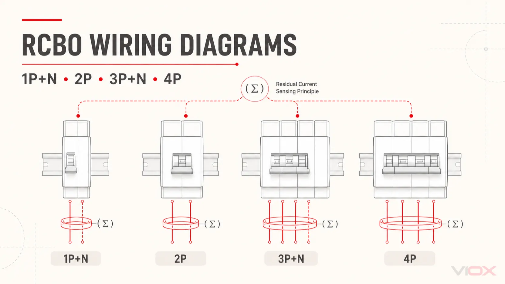
Ang isang wiring diagram ng RCBO ay dapat tumukoy sa tatlong magkakaibang bagay: kung aling mga konduktor ang dumadaan sa residual-current sensing system, kung aling mga pole ang sabay na bumubukas, at kung aling mga pole ang may overcurrent protection. Ang mga ito ay magkakaugnay, ngunit hindi maaaring pagpalitin.
Para sa mga single-phase circuit, ang sinusubaybayang set ay karaniwang kinabibilangan ng line at neutral. Para sa mga three-phase four-wire circuit, karaniwan itong kinabibilangan ng L1, L2, L3, at neutral. Ang protective earth (PE) ay hindi nagdadala ng normal na load current at nananatili sa labas ng switched at monitored load-current path ng RCBO.
Hangganan ng kaligtasan: Ang mga diagram sa ibaba ay nagpapaliwanag ng mga path ng konduktor; hindi ito mga tagubilin sa pag-install. Ang gawaing may kaugnayan sa fixed distribution-board ay dapat tapusin at beripikahin ng isang kwalipikadong electrical professional. Ang eksaktong diagram ng catalog-number ng RCBO, mga tagubilin ng manufacturer, mga naaangkop na panuntunan sa pag-wire, at mga kinakailangan ng panel system ang laging dapat masunod.
Mabilis na Sanggunian para sa RCBO Wiring Diagram
| Pagmamarka ng device | Karaniwang konteksto ng circuit | Mga konduktor sa paghahambing ng residual-current | Karaniwang pagsasaayos ng overcurrent | Detalye ng neutral na dapat beripikahin | Huwag mag-assume |
|---|---|---|---|---|---|
| 1P+N | Single-phase L+N na final circuit | L at N | Ang phase ay karaniwang may overcurrent release | Switched terminal, solid neutral, flying lead, o plug-on neutral | Posisyon ng terminal, direksyon ng feed, o neutral switching |
| 2P | Single-phase L+N o iba pang aprubadong two-conductor circuit | Parehong current-carrying conductors | Isa o parehong pole, depende sa disenyo | Aling pole ang itinalaga bilang N at kung ang parehong pole ay protektado | Ang dalawang physical pole ay nangangahulugan ng dalawang magkaparehong overcurrent release |
| 3P+N | Three-phase four-wire circuit | L1, L2, L3, at N | Ang mga three-phase pole ay karaniwang may mga overcurrent release | Kung may N switch, paano ito ikinakabit, at ang pagkakasunod-sunod ng operasyon nito | Ang konstruksyon ng 3P+N ng bawat manufacturer ay pare-pareho |
| 4P | Three-phase four-wire circuit | L1, L2, L3, at N | Dapat kumpirmahin mula sa functional diagram | Posisyon ng neutral pole, proteksyon, at pagkakasunod-sunod ng pag-switch | Ang lahat ng apat na pole ay naglalaman ng magkakaparehong overcurrent release |
Ang VIOX ay nagbibigay ng mga RCBO sa mga configuration na 1P+N, 2P, 3P+N, at 4P. Ang talahanayan ay tumutukoy lamang sa topology; gamitin ang eksaktong datasheet ng modelong VIOX upang kumpirmahin ang layout ng terminal at mga internal na function nito.
Paano Basahin ang mga Diagram
Ang mga konseptwal na diagram ay gumagamit ng parehong visual grammar sa kabuuan:
[OC]nangangahulugan na ang konduktor ay may overcurrent release sa ipinakitang functional arrangement.[SW]nangangahulugan na ang pole ay mekanikal na binubuksan o isinasara (switched) ngunit hindi tinutukoy dito bilang protektado laban sa overcurrent.(Σ)ay ang hangganan ng residual-current sensing. Ang bawat normal na konduktor na nagdadala ng kuryente na kabilang sa protektadong circuit ay dapat sumunod sa landas na itinakda ng device.TESTay ang internal test circuit ng device. Ang koneksyon nito ay maaaring maging dahilan upang maging mahalaga ang direksyon ng supply.PEay protective earth. Nilalagpasan nito ang RCBO at nananatiling tuloy-tuloy hanggang sa load.SUPPLYatLOADay mga functional na bahagi, hindi unibersal na posisyon ng terminal sa itaas at ibaba.
Ang mga simbolong ito ay naglalarawan ng function, hindi ang pisikal na internal ng bawat RCBO. Ang nakalimbag na schematic sa device o sa instruction sheet nito ay maaaring gumamit ng ibang mga simbolo.
Ang Current-Balance Rule na ibinabahagi ng bawat RCBO
Inihahambing ng isang RCBO ang instantaneous current sa lahat ng conductor sa loob ng residual-current sensing boundary nito. Sa pinapayak na anyo:
IΔ = |Σ I(monitored conductors)|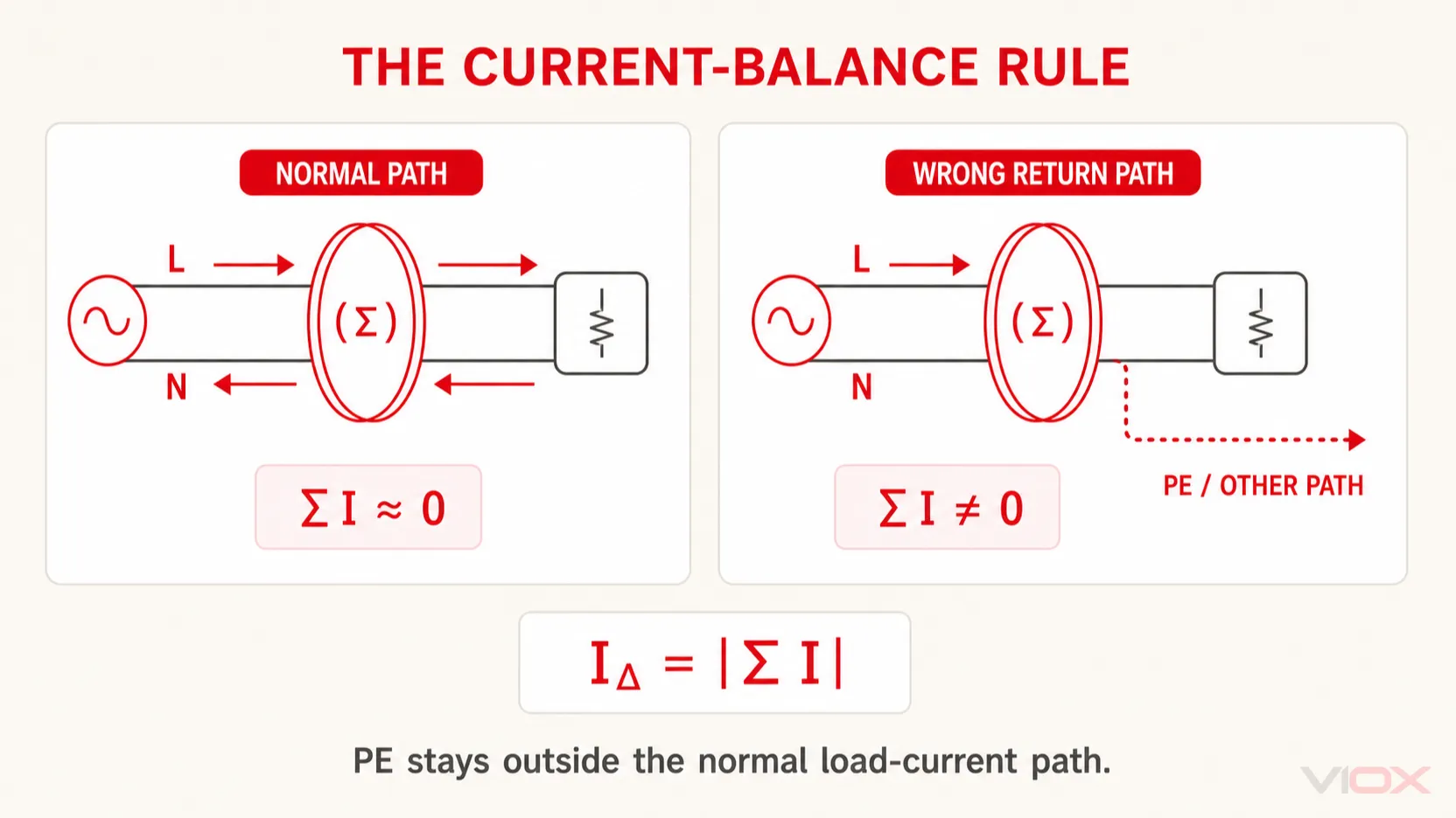
Para sa isang L+N circuit, ang load current na lumalabas sa L ay dapat bumalik sa pamamagitan ng parehong N path ng RCBO. Para sa isang three-phase four-wire circuit, ang vector sum ay sumasaklaw sa L1, L2, L3, at N. Ang mga phase current ay hindi kailangang maging numerically equal; ang isang unbalanced load ay maaari pa ring makagawa ng near-zero vector sum kapag ang lahat ng return current ay nananatili sa loob ng monitored set.
Ito ang dahilan kung bakit ang isang borrowed neutral ay maaaring mag-trip ng RCBO kahit na ang phase conductor ay nakakonekta sa tamang device. May ilang kuryente na bumabalik sa pamamagitan ng conductor na nasa labas ng sensing boundary ng RCBO na iyon, kaya ang sinusukat na sum ay hindi na balanse.
Wiring Diagram ng 1P+N RCBO
Ang 1P+N RCBO ay karaniwang ginagamit para sa single-phase final circuit. Ang parehong line at neutral ay kasali sa residual-current measurement, habang ang phase naman ay karaniwang naglalaman ng overcurrent release. Ang +N na notasyon ay hindi, sa sarili nito, nagtatakda kung ang neutral ay switched, solid, konektado sa pamamagitan ng flying lead, o konektado sa pamamagitan ng plug-on system.
1P+N RCBO — KONSEPTWAL NA TUNGKULINAng mahalagang pagsusuri ay hindi lamang kung ang isang wire ay pumasok sa isang L terminal at ang isa naman ay pumasok sa isang N terminal. Kumpirmahin na:
- ang mga supply at load conductor ay nasa mga gilid na ipinapakita para sa catalog number na iyon;
- ang neutral ng circuit ay bumabalik sa pamamagitan ng itinalagang RCBO neutral arrangement;
- ang isang flying lead, plug-on neutral, o hiwalay na reference lead ay nakakonekta nang eksakto ayon sa tinukoy;
- ang load neutral ay hindi sumasama sa downstream neutral ng ibang circuit; at
- ang test button ay gumagana pagkatapos mai-install at ma-verify ang circuit ayon sa mga tagubilin ng manufacturer.
Huwag ilipat ang terminal pattern mula sa isang 1P+N product family patungo sa iba. Ang mga compact DIN-rail at consumer-unit RCBO ay maaaring magmukhang magkatulad habang gumagamit ng magkaibang neutral at busbar arrangement.
2P RCBO Wiring Diagram
Ang isang 2P RCBO ay nagbibigay ng dalawang mechanically linked na daluyan ng kuryente. Sa isang L+N application, ang parehong line at neutral ay karaniwang dumadaan sa residual-current sensing system at bumubukas ayon sa disenyo ng device. Gayunpaman, 2P Ang pag-iisa nito ay hindi nagpapatunay na ang parehong pole ay may magkaparehong overcurrent release.
2P RCBO — KONSEPTWAL NA GAMIT.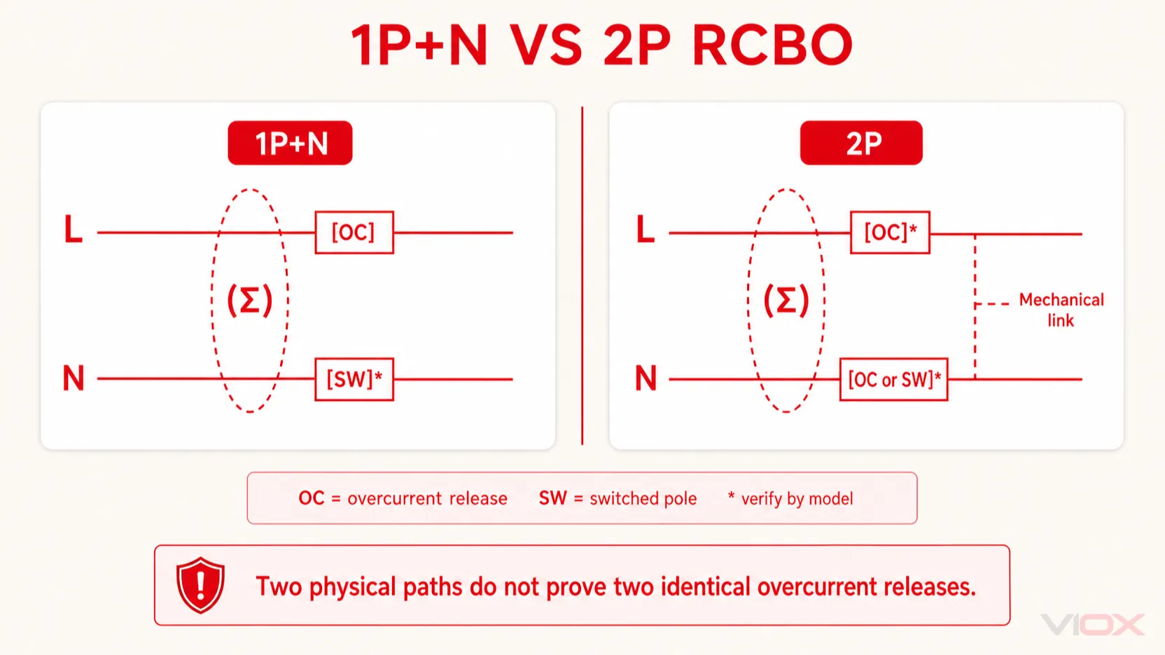
Ang pagkakaibang ito ay mahalaga sa mga system kung saan ang alinman sa current-carrying conductor ay hindi dapat ituring na neutral lamang. Ang two-conductor supply arrangement, pole protection, mga kinakailangan sa disconnection, at pagkakakilanlan ng conductor ay dapat na tugma sa partikular na RCBO at sa mga naaangkop na panuntunan sa pag-install.
Ang isang 2P RCBO at isang 1P+N RCBO ay maaaring parehong tumanggap ng koneksyong L at N, ngunit hindi ito nangangahulugan na sila ay functional substitutes. Ihambing ang schematic, bilang ng mga protected pole, voltage arrangement, neutral designation, switching behavior, at aprubadong aplikasyon bago gumawa ng pagpapalit.
3P+N RCBO Wiring Diagram
Ang isang 3P+N RCBO ay idinisenyo para sa isang aprubadong three-phase four-wire arrangement. Ang L1, L2, L3, at N ang bumubuo sa kumpletong residual-current comparison set. Ang tatlong phase pole ay karaniwang may mga overcurrent release; ang neutral path at ang switching behavior nito ay nakadepende sa partikular na modelo.
3P+N RCBO — KONSEPTWAL NA GAMITAng neutral ang nagdadala ng imbalance ng mga phase load current, ngunit kailangan pa rin itong mapabilang sa loob ng residual-current comparison. Ang pagdaan nito sa labas ng RCBO ay magdudulot upang ang normal na unbalanced load current ay magmukhang residual current.
Ang pagkakasunod-sunod ng phase (phase sequence) at ang posisyon ng terminal ay magkahiwalay na usapin. Ang isang drawing na naglalagay ng label na L1, L2, at L3 ay hindi nagtatakda ng unibersal na pagkakasunod-sunod ng terminal mula kaliwa pakanan, at hindi nito pinapalitan ang mga pagsusuri sa phase-sequence ng system.
Para sa isang three-phase three-wire load, huwag mag-imbento sa pamamagitan ng pag-iwan sa N path na hindi ginagamit dahil lamang walang neutral ang load. Kumpirmahin kung ang eksaktong 3P+N RCBO at ang test circuit nito ay aprubado para sa ganoong arrangement. Ang ilang device ay nangangailangan ng koneksyon ng neutral para sa kanilang electronics o function ng pag-test.
Diagram ng Pagkakabit ng 4P RCBO
Ang isang 4P RCBO ay nagbibigay ng apat na magkakaugnay na daluyan ng kuryente para sa isang deklaradong aplikasyon. Sa isang three-phase four-wire system, ang mga ito ay karaniwang L1, L2, L3, at N, at ang lahat ng apat na konduktor ay bumubuo sa minomonitor na set. Ang 4P marking ay hindi pa rin nagpapatunay na ang apat na pole ay may magkakaparehong overcurrent release.
4P RCBO — KONSEPTWAL NA FUNCTION.Ang dokumentasyon ng modelo ay dapat sumagot sa apat na tanong na hindi kayang sagutin ng isang generic na four-line drawing:
- Aling posisyon ang neutral pole?
- Ang neutral pole ba ay may overcurrent protection, switching lamang, o ibang arrangement?
- Ang neutral ba ay nauunang mag-connect bago ang mga phase pole at huling nagdi-disconnect pagkatapos ng mga ito kung kinakailangan ng disenyo ng device?
- Aling panig ang dapat lagyan ng supply upang gumana nang tama ang internal electronics at TEST circuit?
Huwag kailanman ibatay ang mga sagot na ito sa lapad ng enclosure o sa linkage ng handle lamang.
Ang 3P+N at 4P ay hindi awtomatikong magkasingkahulugan
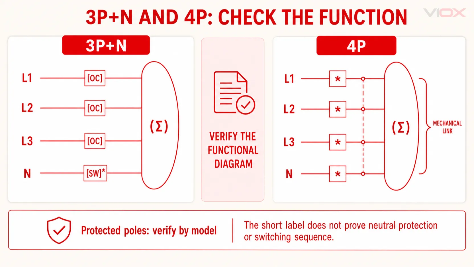
Nag-o-overlap ang mga terminong ito sa pang-araw-araw na paghahanap ng produkto dahil pareho silang maaaring maglarawan ng kagamitang ginagamit sa L1, L2, L3, at N. Hindi nito maaasahang naipapahayag ang parehong internal na konstruksyon sa lahat ng manufacturer at merkado.
| Label | Ano ang karaniwang ipinapahiwatig nito | Ano ang hindi nito pinapatunayan |
|---|---|---|
| 3P+N | Tatlong phase path at isang neutral path | Proteksyon sa neutral, paraan ng paglipat (switching method), pagkakasunod-sunod ng paglipat, pagkakaayos ng terminal, o suplay ng TEST-circuit |
| 4P | Apat na magkakadugtong na pole | Na ang bawat pole ay may parehong overcurrent release o na ang anumang pole ay maaaring gamitin bilang neutral |
Ang ligtas na paghahambing ay functional: itugma ang schematic ng manufacturer, impormasyon ng protected-pole, marka ng neutral, rated system, mga kinakailangan sa test-circuit, at mga tagubilin sa pag-install. Huwag magdesisyon base lamang sa label ng maikling pole.
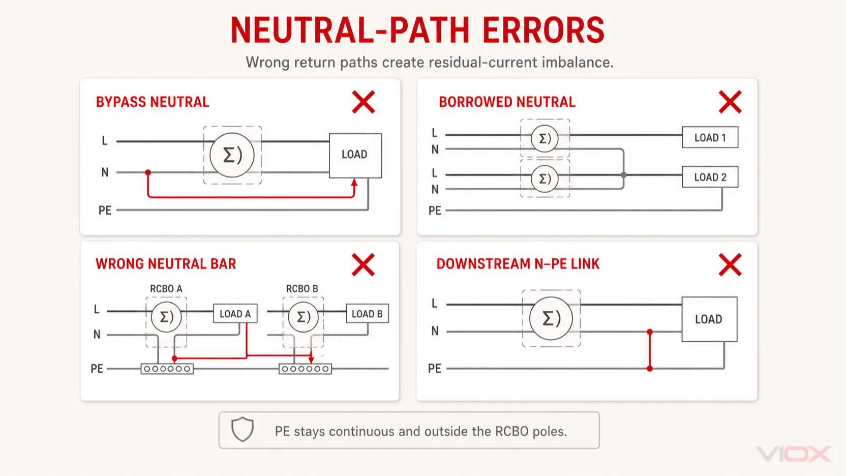
Mga pagkakamali sa wiring ng Neutral at PE
| Pagkakamali sa diagram o panel | Bakit mali ang daloy ng kuryente | Inaasahang gawi o behavior | Tamang beripikasyon |
|---|---|---|---|
| Ang load neutral ay lumalagpas sa RCBO nito | Ang phase current ay lumalabas sa sensor ngunit ang neutral current ay bumabalik sa labas nito | Agaran o nakadepende sa load na pag-trip | Sundan ang buong load neutral hanggang sa terminal o koneksyong itinalaga ng modelo |
| Pinagsalo o hiniram na neutral | Ang kuryente mula sa isang circuit ay bumabalik sa pamamagitan ng neutral ng ibang circuit | Isa o maraming RCBO ang maaaring mag-trip habang nagbabago ang mga load | Tukuyin ang pagmamay-ari ng circuit at panatilihing magkahiwalay ang mga downstream neutral zone |
| Ang neutral ay nakakabit sa maling downstream bar | Naghahalo ang mga residual-current zone ng mga protected circuit | Nagti-trip ang breaker pagkatapos ng gawaing elektrikal o kapag may ibang load na gumagana | I-verify ang arkitektura ng neutral-bar base sa diagram ng panel |
| Koneksyong N–PE sa downstream | Ang ilang normal na return current ay maaaring mahati patungo sa PE | Operasyon ng residual-current at hindi ligtas na kondisyon ng fault | Hanapin at itama ang downstream connection alinsunod sa mga naaangkop na panuntunan |
| Ang PE ay idinaan sa isang pole ng RCBO | Ang protective conductor ay maling itinuring bilang isang switched load conductor | Pagkawala ng protective continuity o hindi sumusunod na proteksyon | Panatilihing tuloy-tuloy ang PE at ilabas ito sa mga pole ng RCBO |
| Ipinapalagay ang supply at load sides | Maaaring magmukhang konektado ang mekanismo ng proteksyon habang ang test circuit o electronics ay hindi wastong nasusuplayan | Pagkabigo ng function na TEST o pag-uugali na labas sa idineklarang disenyo | Sundin ang diagram para sa eksaktong catalog number. |
Huwag ituring ang pag-trip ng RCBO bilang patunay na depektibo ang device. Ang maling neutral path ay isang error sa wiring ng system, hindi isyu sa laki ng overcurrent. Para sa mas malawak na desisyon sa specification ng device, gamitin ang Gabay sa pagpili ng RCBO; huwag subukang lutasin ang mga error sa neutral-path sa pamamagitan ng pagpapalit ng current rating, trip curve, o uri ng residual-current.
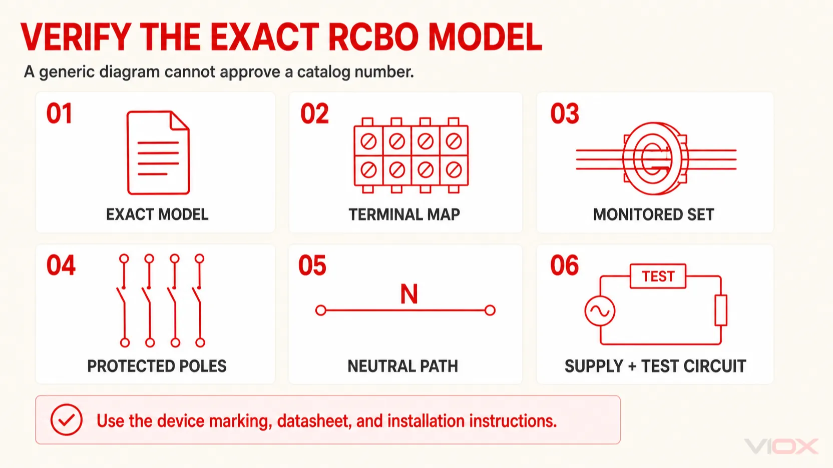
Exact-Model RCBO Wiring Verification Card
Bago aprubahan ang diagram ng RCBO para sa isang panel, itala ang mga item na ito mula sa marking ng device, datasheet, at mga tagubilin sa pag-install:
| Suriin | Kinakailangang ebidensya |
|---|---|
| Eksaktong pagkakakilanlan | Manufacturer, pamilya ng produkto, kumpletong catalog number, at rebisyon kung saan ito nakasaad |
| Electrical system | Rated voltage, frequency, bilang ng phases, pagkakaroon ng neutral, at aprubadong circuit arrangement |
| Terminal map | Mga koneksyon para sa L/L1/L2/L3/N, supply, load, busbar, cable, at auxiliary na itinalaga ng manufacturer |
| Residual-current path | Bawat normal na current-carrying conductor na kasama sa idineklarang sensing arrangement ng device |
| Overcurrent function | Aling mga pole ang may proteksyon laban sa overload at short-circuit |
| Disconnection function | Aling mga pole ang sabay na nag-o-on/off at anumang idineklarang neutral operating sequence |
| Neutral architecture | Terminal, solid-neutral, flying-lead, plug-on-neutral, o iba pang koneksyon na partikular sa modelo |
| Direksyon ng supply | Itaas, ibaba, reversible, o kung hindi man ay limitado ng eksaktong mga tagubilin ng produkto |
| TEST circuit | Kinakailangang voltage path at mga tagubilin sa pagsubok ng manufacturer |
| Pagkakatugma ng panel | Inaprubahang busbar, mounting system, accessories, uri ng conductor, at mga kinakailangan sa koordinasyon |
| Mga panuntunan sa pag-install | Mga naaangkop na pambansang tuntunin, mga kinakailangan sa isolation, pagkakakilanlan ng konduktor, at pamamaraan ng pag-verify |
Ang pagkakaiba sa pagitan ng line, load, at neutral ay ipinaliwanag nang higit pa sa gabay ng VIOX para sa mga wire na line, load, at neutral. Para sa saklaw ng pamantayan ng produkto at mga implikasyon sa pagkuha, tingnan ang paliwanag ng VIOX sa IEC 61009-1 para sa mga RCBO.
Ano ang Hindi Mapapatunayan ng isang Generic na Diagram ng RCBO
Ang isang konseptwal na diagram ng koneksyon ng RCBO ay makakapagtatag ng tamang paraan ng pangangatwiran, ngunit hindi nito makukumpirma ang:
- mga pisikal na numero ng terminal o ang posisyon nito sa enclosure;
- kung pinapayagan ng device ang supply mula sa itaas o ibaba;
- ang eksaktong paraan ng pag-switch, proteksyon, o koneksyon ng neutral;
- ang supply path ng internal TEST-circuit;
- compatibility sa isang partikular na busbar o distribution board;
- kapasidad ng conductor, haba ng pag-strip, o torque ng terminal;
- pagiging angkop para sa three-wire system, DC circuit, espesyal na load, o instalasyong panrehiyon;
- ang current rating, residual operating-current rating, curve, type, o breaking capacity ng device; o
- pagsunod o sertipikasyon ng isang partikular na catalog number.
Ang mga RCBO para sa gamit sa bahay at katulad na aplikasyon ay nasa ilalim ng saklaw ng produkto ng IEC 61009-1, ngunit ang pamantayan ay hindi ginagawang awtoridad sa pag-install para sa partikular na modelo ang isang generic na diagram online. Ang saklaw ng kasalukuyang edisyon at ang idineklarang pagsunod ng produkto ay dapat suriin nang hiwalay sa pagsunod sa lokal na wiring code.
Nag-aalok ang VIOX Mga pamilya ng produktong RCBO sa mga configuration na 1P+N, 2P, 3P+N, at 4P. Para sa disenyo ng panel, pagpapalit, o proyekto ng pagkuha ng supply, humingi ng eksaktong datasheet ng modelo ng VIOX RCBO at kumpirmasyon ng wiring bago pinalin ang schematic.
Mga Nakatuong Tanong
Dumadaan ba ang neutral wire sa isang RCBO?
Sa isang L+N o three-phase four-wire circuit, ang load neutral ay karaniwang sumusunod sa neutral path na itinakda ng RCBO kaya kasama ito sa paghahambing ng residual-current. Ang pisikal na pagkakaayos ay maaaring terminal, flying lead, solid-neutral path, o plug-on connection. Gamitin ang eksaktong diagram ng modelo.
Maaari bang lagyan ng supply ang RCBO mula sa itaas o sa ibaba?
Kapag pinahintulutan lamang ito ng manufacturer para sa partikular na catalog number na iyon. Ang reverse connection ay maaaring makaapekto sa internal electronics o sa TEST circuit kahit na mukhang simetriko ang main current path.
Ang 3P+N RCBO ba ay katulad ng 4P RCBO?
Hindi kinakailangan. Ang parehong label ay maaaring iugnay sa L1, L2, L3, at N, ngunit walang label ang nagpapatunay sa pagkakaayos ng protected-pole o sa gawi ng neutral. Ihambing ang functional schematics at datasheets.
Dumadaan ba ang protective earth sa RCBO?
Hindi. Ang PE ay nananatiling tuloy-tuloy patungo sa load at nasa labas ng normal na switched at monitored load-current paths ng RCBO. Ang kuryenteng dumadaloy sa PE dahil sa fault ay isa sa mga dahilan kung bakit ang mga monitored conductor ay hindi na nagreresulta sa humigit-kumulang zero.